CN211330832U - Compression roller structure of edge rolling machine - Google Patents
Compression roller structure of edge rolling machine Download PDFInfo
- Publication number
- CN211330832U CN211330832U CN201922317150.6U CN201922317150U CN211330832U CN 211330832 U CN211330832 U CN 211330832U CN 201922317150 U CN201922317150 U CN 201922317150U CN 211330832 U CN211330832 U CN 211330832U
- Authority
- CN
- China
- Prior art keywords
- rotating shaft
- rolling machine
- far away
- rotation
- wall
- Prior art date
- Legal status (The legal status is an assumption and is not a legal conclusion. Google has not performed a legal analysis and makes no representation as to the accuracy of the status listed.)
- Expired - Fee Related
Links
Images


Abstract
The utility model provides a rolling machine's compression roller structure, the on-line screen storage device comprises a base, the top of base is equipped with the backup pad, two first axis of rotation and second axis of rotation are installed to the inboard of backup pad, first axis of rotation with compression roller and winding up roller have all been cup jointed on the outer wall of second axis of rotation, equal symmetry is equipped with the spout on the both ends outer wall of compression roller, and is a plurality of all be equipped with the draw-in groove on the inside wall of spout, just the holding ring has all been cup jointed at the both ends of compression roller, two the inboard equal symmetry of holding ring is equipped with the slide bar, and is a plurality of one side of slide bar all is equipped with the connecting block, and is a plurality of the one end that the connecting block is far away all is equipped with the baffle, and is a plurality of coupling assembling is all installed to the one end of baffle. The utility model discloses a holding ring, coupling assembling, baffle and self-locking bolt have realized sheet metal's location, have improved edge rolling efficiency.
Description
Technical Field
The utility model mainly relates to the technical field of edge rolling machines, in particular to a compression roller structure of an edge rolling machine.
Background
The existing edge rolling machine is generally used for rolling a metal section into a circular ring or a flange, but a press roller of the edge rolling machine does not generally have a positioning structure, and when the press roller presses the edge rolling roller to roll the metal sheet, the press roller does not have the positioning structure, so that the position of the metal sheet is easily changed, and even the press roller and the edge rolling roller are separated from each other seriously, the edge rolling failure is caused, the edge rolling efficiency is further influenced, and the processing efficiency is reduced. Therefore, there is a need to develop a press roller structure of a rolling machine, which is convenient for positioning the metal plate and improves the rolling efficiency.
SUMMERY OF THE UTILITY MODEL
The utility model mainly provides a compression roller structure of edge rolling machine for solve the technical problem who proposes among the above-mentioned background art.
The utility model provides a technical scheme that above-mentioned technical problem adopted does:
a compression roller structure of a rolling machine comprises a base, wherein supporting plates are welded and fixed side by side on the top end of the base close to an outer edge, a first rotating shaft and a second rotating shaft are horizontally installed on the inner sides of the two supporting plates from top to bottom, a compression roller main body and a rolling roller are fixedly sleeved on the outer walls of the first rotating shaft and the second rotating shaft, sliding grooves are symmetrically arranged on the outer walls of the two ends of the compression roller main body, clamping grooves are formed in the inner side walls of the sliding grooves, positioning rings are sleeved at the two ends of the compression roller main body, sliding rods are symmetrically welded and fixed on the inner sides of the two positioning rings, the sliding rods are connected with the sliding grooves in a sliding mode, a connecting block is welded and fixed on one side of each sliding rod, a plurality of the connecting blocks are far away from one ends of the sliding rods, a baffle is fixedly installed on the same end of each sliding rod, and the baffles are, it is a plurality of the baffle is kept away from a plurality of coupling assembling is all installed to the one end of slide bar, and is a plurality of coupling assembling keeps away from a plurality of the one end of baffle is all with a plurality of the inner wall fixed connection of draw-in groove, and two equal symmetry runs through on the outer wall of holding ring is equipped with the location screw, and is a plurality of the location screw all runs through a plurality of the slide bar, it is a plurality of self-locking bolt is all installed to the one end of location screw, and is a plurality of self-locking bolt all with a plurality of the meshing of location screw is connected.
Further, locking rings are installed at the joint of the first rotating shaft and the compression roller main body, each locking ring comprises an outer ring and an inner ring, the outer wall of each outer ring is meshed with the inner wall of the compression roller main body, air bag cavities are arranged between the inner walls of the outer rings and the outer walls of the inner rings, and air bags are installed inside the air bag cavities.
Further, two the intake pipe is all installed to one side of gasbag, two the intake pipe is kept away from two the one end of gasbag all runs through the outer loop extends to its externally mounted has the admission valve.
It is further, a plurality of coupling assembling all includes first mounting panel, and is a plurality of one side of first mounting panel all with a plurality of the inner wall fixed connection of draw-in groove is a plurality of the equal fixed mounting of one end of first mounting panel has the spring, and is a plurality of the spring is kept away from a plurality of the equal fixedly connected with second mounting panel of one end of first mounting panel, and is a plurality of the second mounting panel is kept away from a plurality of one side of spring all with a plurality of baffle fixed connection.
Further, first axis of rotation with the both ends of second axis of rotation all run through two the backup pad is through ball bearing and rotates the connection, first axis of rotation with the second axis of rotation extends to two driven gear and driving gear are installed respectively to the outer one end of backup pad, the driving gear pass through the chain with driven gear rotates and connects, just the second axis of rotation is kept away from the one end of driving gear is connected with hydraulic motor through the rotor rotation, hydraulic motor's bottom with the top fixed connection of base.
Further, the compression roller main body and the winding roller can be detached.
Furthermore, handles are installed at one ends of the self-locking bolts.
Compared with the prior art, the beneficial effects of the utility model are that:
one of the two positioning rings are connected with each other through a connecting block, the position of the baffle is limited through the connecting assembly in the motion process of the baffle, the baffle can shield the chute, the influence of the chute on the edge rolling of the metal plate is prevented, when the positioning rings move to a proper position, the positioning rings are fixed through positioning screws and self-locking bolts, the metal plate is positioned through the positioning rings, the metal plate is prevented from deviating from the edge rolling position, the positioning of the metal plate is realized, and the edge rolling efficiency is improved;
and secondly, the utility model discloses having stabilized first axis of rotation and compression roller, having improved the edge rolling effect, first axis of rotation and compression roller are locked respectively to outer loop and the inner ring through the locking ring, prevent that the compression roller from breaking away from first axis of rotation, lead to the device can't be used, when the inner ring damaged, through opening the admission valve, aerify in to the gasbag through the intake pipe, the gasbag can surround first axis of rotation this moment, prevent that first axis of rotation and compression roller from breaking away from, prevent that the device from further damaging, prolonged its life.
The present invention will be explained in detail with reference to the drawings and specific embodiments.
Drawings
Fig. 1 is a schematic view of the overall structure of the present invention;
FIG. 2 is a schematic view of the positioning ring of the present invention;
FIG. 3 is a sectional view of the compression roller structure of the present invention;
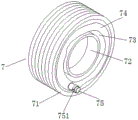
fig. 4 is a schematic view of the locking ring structure of the present invention.
In the figure: 1. a base; 11. a support plate; 2. a positioning ring; 21. a slide bar; 211. connecting blocks; 22. positioning the screw hole; 23. a self-locking bolt; 231. a handle; 3. a winding roller; 31. a second rotating shaft; 4. a hydraulic motor; 41. a driving gear; 42. a driven gear; 5. a compression roller main body; 51. a first rotating shaft; 52. a chute; 53. a baffle plate; 54. a card slot; 6. a connecting assembly; 61. a first mounting plate; 62. a spring; 63. a second mounting plate; 7. locking a ring; 71. an outer ring; 72. an inner ring; 73. a balloon lumen; 74. an air bag; 75. an air inlet pipe; 751. an intake valve.
Detailed Description
In order to facilitate understanding of the present invention, the present invention will be described more fully with reference to the accompanying drawings, in which several embodiments of the present invention are shown, but the present invention can be implemented in different forms, and is not limited to the embodiments described in the text, but rather, these embodiments are provided to make the disclosure of the present invention more thorough and comprehensive.
It will be understood that when an element is referred to as being "secured to" another element, it can be directly on the other element or intervening elements may be present, and when an element is referred to as being "connected" to another element, it can be directly connected to the other element or intervening elements may also be present, as the terms "vertical", "horizontal", "left", "right" and the like are used herein for descriptive purposes only.
Unless defined otherwise, all technical and scientific terms used herein have the same meaning as commonly understood by one of ordinary skill in the art to which this invention belongs, and the use of the term knowledge in the specification of the present invention is for the purpose of describing particular embodiments and is not intended to limit the present invention, and the term "and/or" as used herein includes any and all combinations of one or more of the associated listed items.
Please refer to fig. 1-4 in greater detail, a press roller structure of a rolling machine includes a base 1, wherein support plates 11 are welded and fixed side by side at the top end of the base 1 near the outer edge, a first rotating shaft 51 and a second rotating shaft 31 are horizontally installed at the inner sides of the two support plates 11 from top to bottom, a press roller main body 5 and a rolling roller 3 are fixedly sleeved on the outer walls of the first rotating shaft 51 and the second rotating shaft 31, sliding grooves 52 are symmetrically arranged on the outer walls of the two ends of the press roller main body 5, clamping grooves 54 are arranged on the inner walls of the sliding grooves 52, positioning rings 2 are sleeved at the two ends of the press roller main body 5, sliding rods 21 are symmetrically welded and fixed on the inner sides of the two positioning rings 2, the sliding rods 21 are slidably connected with the sliding grooves 52, connecting blocks 211 are welded and fixed on one side of the sliding rods 21, and a baffle 53 is fixedly installed at the ends of the connecting blocks 211 far away from the sliding rods 21, it is a plurality of baffle 53 all with a plurality of draw-in groove 54 sliding connection, it is a plurality of baffle 53 is kept away from a plurality ofly coupling assembling 6, a plurality of coupling assembling 6 is kept away from a plurality of baffle 53's one end all with a plurality of draw-in groove 54's inner wall fixed connection, and two equal symmetry runs through on the outer wall of holding ring 2 and is equipped with positioning screw hole 22, and is a plurality of positioning screw hole 22 all runs through a plurality of slide bar 21, it is a plurality of self-locking bolt 23 is all installed to positioning screw hole 22's one end, and is a plurality of self-locking bolt 23 all with a plurality of positioning screw hole 22 meshes the connection.
Please refer to fig. 4 again, locking rings 7 are mounted at the joints of the first rotating shaft 51 and the pressing roller main body 5, each of the two locking rings 7 includes an outer ring 71 and an inner ring 72, outer walls of the two outer rings 71 are engaged with an inner wall of the pressing roller main body 5, an air bag cavity 73 is disposed between the inner wall of the two outer rings 71 and the outer wall of the two inner rings 72, an air bag 74 is mounted in each of the two air bag cavities 73, an air inlet pipe 75 is mounted on one side of each of the two air bags 74, and one end of each of the two air inlet pipes 75, which is far away from the two air bags 74, extends through the outer rings 71 to the outside of the outer rings and. In this embodiment, the first rotating shaft 51 and the pressing roller body 5 are respectively locked by the outer ring 71 and the inner ring 72 of the locking ring 7, the pressing roller body 5 is prevented from being separated from the first rotating shaft 51, so that the device cannot be used, when the inner ring 72 is damaged, the air bag 74 is inflated through the air inlet pipe 75 by opening the air inlet valve 751, and the air bag 74 surrounds the first rotating shaft 51 at this time, so that the first rotating shaft 51 is prevented from being separated from the pressing roller body 5, and the device is prevented from being further damaged.
Please refer to fig. 3 again, each of the connecting assemblies 6 includes a first mounting plate 61, one side of each of the first mounting plates 61 is fixedly connected to the inner wall of each of the locking slots 54, one end of each of the first mounting plates 61 is fixedly mounted with a spring 62, one end of each of the springs 62 far away from the first mounting plates 61 is fixedly connected to a second mounting plate 63, and one side of each of the second mounting plates 63 far away from the springs 62 is fixedly connected to the baffles 53. In the present embodiment, the second mounting plate 63 is fixedly connected to the baffle 53, so that the spring 62 limits the position of the baffle 53 to prevent the baffle 53 from moving excessively to affect the rolling of the metal plate.
Please refer to fig. 1-2 again, two ends of the first rotating shaft 51 and the second rotating shaft 31 penetrate through the two support plates 11 and are rotatably connected through ball bearings, one end of the first rotating shaft 51 and the second rotating shaft 31 extending out of the two support plates 11 is respectively provided with a driven gear 42 and a driving gear 41, the driving gear 41 is rotatably connected with the driven gear 42 through a chain, one end of the second rotating shaft 31 far away from the driving gear 41 is rotatably connected with a hydraulic motor 4 through a rotor, the bottom of the hydraulic motor 4 is fixedly connected with the top of the base 1, the press roller main body 5 and the winding roller 3 are both detachable, and one end of each of the self-locking bolts 23 is provided with a handle 231. In this embodiment, through the work of hydraulic motor 4, drive driving gear 41 rotates, because driving gear 41 passes through the chain and is connected with driven gear 42 rotation, consequently driving gear 41 drives driven gear 42 and rotates, and then second axis of rotation 31 rotates, and second axis of rotation 31 drives winding up roller 3 and rotates, realizes the edge rolling of sheet metal.
The utility model discloses a concrete operation as follows:
firstly, the distance between the two positioning rings 2 on the outer wall of the compression roller main body 5 is adjusted according to the width of the metal sheet, the sliding connection between the sliding rod 21 and the sliding groove 52 facilitates the movement of the two positioning rings 2, when the two positioning rings 2 approach to each other or depart from each other, the baffle 53 is driven to move through the connecting block 211 due to the sliding connection between the baffle 53 and the clamping groove 54, the position of the baffle 53 is limited through the connecting assembly 6 during the movement of the baffle 53, so that the baffle 53 can shield the sliding groove 52, the influence of the sliding groove 52 on the curling of the metal sheet is prevented, when the positioning rings 2 move to proper positions, the positioning rings 2 are fixed through the positioning screw holes 22 and the self-locking bolts 23, the metal sheet is positioned through the positioning rings 2, the metal sheet is prevented from deviating from the curling position, the curling work can be carried out, during the curling process, the first rotating shaft 51 and the compression roller main body 5 are respectively locked, when the inner ring 72 is damaged, the air inlet valve 751 is opened, the air bag 75 inflates the air bag 74, the air bag 74 surrounds the first rotating shaft 51 at the moment, the first rotating shaft 51 is prevented from being separated from the compression roller body 5, the device is prevented from being further damaged, and time is saved for maintenance.
The present invention has been described above with reference to the accompanying drawings, and it is obvious that the present invention is not limited by the above-mentioned manner, if the method and the technical solution of the present invention are adopted, the present invention can be directly applied to other occasions without substantial improvement, and the present invention is within the protection scope of the present invention.
Claims (7)
1. The utility model provides a compression roller structure of edge rolling machine, includes base (1), its characterized in that, the top of base (1) is close to outer edgewise welded fastening side by side has backup pad (11), two the inboard of backup pad (11) is equipped with first axis of rotation (51) and second axis of rotation (31) by last horizontal installation down, all fixed the cup jointing has been pressed roller main part (5) and winding up roller (3) on the outer wall of first axis of rotation (51) and second axis of rotation (31), all the symmetry is equipped with spout (52) on the both ends outer wall of pressed roller main part (5), and is a plurality of all be equipped with draw-in groove (54) on the inside wall of spout (52), just the both ends of pressed roller main part (5) all cup jointed holding ring (2), two the inboard of holding ring (2) all the symmetry welded fastening has slide bar (21), and is a plurality of slide bar (21) all with a plurality of spout (52) sliding connection, a plurality of connecting blocks (211) are welded and fixed on one side of the sliding rods (21), a plurality of connecting blocks (211) are fixedly provided with baffle plates (53) at one ends far away from the sliding rods (21), the baffle plates (53) are connected with the clamping grooves (54) in a sliding manner, a plurality of connecting assemblies (6) are arranged at one ends far away from the sliding rods (21) of the baffle plates (53), one ends far away from the baffle plates (53) of the connecting assemblies (6) are fixedly connected with the inner walls of the clamping grooves (54), and two equal symmetry runs through on the outer wall of holding ring (2) and is equipped with location screw (22), and is a plurality of location screw (22) all runs through a plurality of slide bar (21), it is a plurality of self-locking bolt (23) are all installed to the one end of location screw (22), and are a plurality of self-locking bolt (23) all with a plurality of location screw (22) meshing is connected.
2. The press roller structure of the rolling machine according to claim 1, wherein a connecting part of the first rotating shaft (51) and the press roller main body (5) is provided with a locking ring (7), two locking rings (7) comprise an outer ring (71) and an inner ring (72), the outer walls of the two outer rings (71) are engaged with the inner wall of the press roller main body (5), an air bag cavity (73) is arranged between the inner walls of the two outer rings (71) and the outer walls of the two inner rings (72), and an air bag (74) is arranged inside the two air bag cavities (73).
3. The press roller structure of the rolling machine according to claim 2, characterized in that an air inlet pipe (75) is installed at one side of each of the two air bags (74), and one end of each of the two air inlet pipes (75) far away from the two air bags (74) extends through the outer ring (71) to the outside of the outer ring, and an air inlet valve (751) is installed on the end of each of the two air inlet pipes.
4. The press roller structure of the rolling machine according to claim 1, wherein the plurality of connecting assemblies (6) comprise a first mounting plate (61), one side of the plurality of first mounting plates (61) is fixedly connected with the inner wall of the plurality of clamping grooves (54), one end of the plurality of first mounting plates (61) is fixedly mounted with a spring (62), one end of the plurality of springs (62) far away from the plurality of first mounting plates (61) is fixedly connected with a second mounting plate (63), and one side of the plurality of second mounting plates (63) far away from the plurality of springs (62) is fixedly connected with the plurality of baffle plates (53).
5. The press roller structure of the rolling machine according to claim 1, wherein two ends of the first rotating shaft (51) and the second rotating shaft (31) penetrate through two support plates (11) and are rotatably connected through ball bearings, one ends of the first rotating shaft (51) and the second rotating shaft (31) extending out of the two support plates (11) are respectively provided with a driven gear (42) and a driving gear (41), the driving gear (41) is rotatably connected with the driven gear (42) through a chain, one end of the second rotating shaft (31) far away from the driving gear (41) is rotatably connected with a hydraulic motor (4) through a rotor, and the bottom of the hydraulic motor (4) is fixedly connected with the top of the base (1).
6. The press roll structure of a rolling machine according to claim 1, characterized in that the press roll main body (5) and the rolling roll (3) are detachable.
7. The press roller structure of the rolling machine as claimed in claim 1, wherein a handle (231) is mounted at one end of each of the self-locking bolts (23).
Priority Applications (1)
| Application Number | Priority Date | Filing Date | Title |
|---|---|---|---|
| CN201922317150.6U CN211330832U (en) | 2019-12-21 | 2019-12-21 | Compression roller structure of edge rolling machine |
Applications Claiming Priority (1)
| Application Number | Priority Date | Filing Date | Title |
|---|---|---|---|
| CN201922317150.6U CN211330832U (en) | 2019-12-21 | 2019-12-21 | Compression roller structure of edge rolling machine |
Publications (1)
| Publication Number | Publication Date |
|---|---|
| CN211330832U true CN211330832U (en) | 2020-08-25 |
Family
ID=72090641
Family Applications (1)
| Application Number | Title | Priority Date | Filing Date |
|---|---|---|---|
| CN201922317150.6U Expired - Fee Related CN211330832U (en) | 2019-12-21 | 2019-12-21 | Compression roller structure of edge rolling machine |
Country Status (1)
| Country | Link |
|---|---|
| CN (1) | CN211330832U (en) |
-
2019
- 2019-12-21 CN CN201922317150.6U patent/CN211330832U/en not_active Expired - Fee Related
Similar Documents
| Publication | Publication Date | Title |
|---|---|---|
| CN204416487U (en) | Large-scale automatic turnover machine | |
| CN211330832U (en) | Compression roller structure of edge rolling machine | |
| CN106269927A (en) | A kind of rolling mill hydraulic manipulator | |
| CN217749588U (en) | Turnover equipment for plate shearing machine | |
| CN203438356U (en) | Centrifugation nodular cast iron pipe cement smearing lining device | |
| CN205873332U (en) | Millet device is taken off to synchronous pulley formula wing wheel | |
| CN205771497U (en) | A kind of stagewise material strip mechanism | |
| CN212552612U (en) | Magnet pressing device for valve element production | |
| CN114158218A (en) | Oil well frequency conversion cabinet with automatic inspection function | |
| CN209502571U (en) | A kind of non-ferrous metal wire rolling forming machine | |
| CN215745224U (en) | Scrap iron and steel processingequipment with high-efficient dust removal function | |
| CN201620345U (en) | Milling wheel capable of fast changing milling width | |
| CN218079720U (en) | Can lift accurate evener of formula | |
| CN215370238U (en) | Roots blower noise reduction structure | |
| CN216501743U (en) | Adjustable edge-wrenching and rib-expanding mechanism | |
| CN211758069U (en) | Efficient rivet turning equipment | |
| CN214646237U (en) | Roll over box machine convenient to dismouting | |
| CN215397067U (en) | A compression roller device for preparing high strength stainless steel lining | |
| CN110661371A (en) | Semi-direct-drive planetary electric roller | |
| CN219294229U (en) | Rotary structure for bumping bamboo tube | |
| CN215924113U (en) | Traction sheave mounting and fixing device for traction machine | |
| CN209871415U (en) | Prevent lax drive belt for panel transportation | |
| CN216397798U (en) | Stamping workpiece loading attachment for bender | |
| CN218930779U (en) | Discharging mechanism for hardware production | |
| CN212468437U (en) | High-efficient vertical mill selection powder machine |
Legal Events
| Date | Code | Title | Description |
|---|---|---|---|
| GR01 | Patent grant | ||
| GR01 | Patent grant | ||
| CF01 | Termination of patent right due to non-payment of annual fee |
Granted publication date: 20200825 Termination date: 20211221 |
|
| CF01 | Termination of patent right due to non-payment of annual fee |