CN211319685U - Government public service satisfaction display board - Google Patents
Government public service satisfaction display board Download PDFInfo
- Publication number
- CN211319685U CN211319685U CN201920981283.0U CN201920981283U CN211319685U CN 211319685 U CN211319685 U CN 211319685U CN 201920981283 U CN201920981283 U CN 201920981283U CN 211319685 U CN211319685 U CN 211319685U
- Authority
- CN
- China
- Prior art keywords
- display board
- rotating
- fixedly installed
- rods
- close
- Prior art date
- Legal status (The legal status is an assumption and is not a legal conclusion. Google has not performed a legal analysis and makes no representation as to the accuracy of the status listed.)
- Expired - Fee Related
Links
- 230000006835 compression Effects 0.000 claims description 14
- 238000007906 compression Methods 0.000 claims description 14
- 238000010586 diagram Methods 0.000 description 3
- 125000002619 bicyclic group Chemical group 0.000 description 2
- 230000000903 blocking effect Effects 0.000 description 2
- 238000010276 construction Methods 0.000 description 2
- 230000005611 electricity Effects 0.000 description 2
- 238000005728 strengthening Methods 0.000 description 2
- 230000009471 action Effects 0.000 description 1
- 230000005540 biological transmission Effects 0.000 description 1
- 230000000694 effects Effects 0.000 description 1
- 238000005516 engineering process Methods 0.000 description 1
- 230000036541 health Effects 0.000 description 1
- 238000009434 installation Methods 0.000 description 1
- 238000000034 method Methods 0.000 description 1
- 230000004048 modification Effects 0.000 description 1
- 238000012986 modification Methods 0.000 description 1
Images


Landscapes
- Photovoltaic Devices (AREA)
Abstract
本实用新型属于展示板领域,尤其是一种政府公共服务满意度展示板,针对现有的展示板需要进行书写并绘制数据表,费时费力,且展示板的功能较为单一,不能将每次统计的结果上传网络并进行公开,大大降低了政府公共服务能力和质量的问题,现提出如下方案,其包括两个侧板,两个侧板相互靠近的一侧均开设有固定孔,两个固定孔内均滑动安装有移动座,侧板上设有驱动装置,驱动装置与两个移动座相适配。本实用新型结构合理,操作方便,该展示板可直接调节伸缩柱的长度并做成柱状图的样式进行展示,省时省力,且展示板能将每次统计的结果上传网络并进行公开,大大提高了政府公共服务能力和质量。

The utility model belongs to the field of display boards, in particular to a display board for the satisfaction of government public services. For the existing display board, it is necessary to write and draw a data table, which is time-consuming and labor-intensive, and the function of the display board is relatively single. The results are uploaded to the network and published, which greatly reduces the problem of the government's public service capacity and quality. The following scheme is now proposed, which includes two side plates, and the two side plates are provided with fixing holes on the side close to each other, and the two fixed A movable seat is slidably installed in the holes, a driving device is arranged on the side plate, and the driving device is adapted to the two movable seats. The utility model has reasonable structure and convenient operation. The display board can directly adjust the length of the telescopic column and display it in the form of a bar graph, which saves time and effort, and the display board can upload the results of each statistics to the network and make public, greatly Improve the government's public service capacity and quality.
Description
技术领域technical field
本实用新型涉及展示板技术领域,尤其涉及一种政府公共服务满意度展示板。The utility model relates to the technical field of display boards, in particular to a government public service satisfaction display board.
背景技术Background technique
公共服务是21世纪公共行政和政府改革的核心理念,包括加强城乡公共设施建设,发展教育、科技、文化、卫生、体育等公共事业,为社会公众参与社会经济、政治、文化活动等提供保障,公共服务以合作为基础,包括加强城乡公共设施建设,强调政府的服务性,强调公民的权利等,为了能够更好的服务于大众,政府有关部门都会定时的展开公民对政府公共服务满意度的调查研究,并将结果公布于众,而公布的途径之一就是将结果书写在展示板上展示出来;Public service is the core concept of public administration and government reform in the 21st century, including strengthening the construction of urban and rural public facilities, developing public utilities such as education, science and technology, culture, health, and sports, and providing guarantees for the public to participate in social economic, political, and cultural activities, etc. Public services are based on cooperation, including strengthening the construction of urban and rural public facilities, emphasizing the service nature of the government, and emphasizing citizens' rights. Investigate and research, and publish the results to the public, and one of the ways to publish is to write the results on the display board and display them;
然而现有的展示板需要进行书写并绘制数据表,费时费力,且展示板的功能较为单一,不能将每次统计的结果上传网络并进行公开,大大降低了政府公共服务能力和质量。However, the existing display boards need to write and draw data tables, which is time-consuming and labor-intensive, and the functions of the display boards are relatively simple, and the results of each statistics cannot be uploaded to the network and made public, which greatly reduces the government's public service capacity and quality.
实用新型内容Utility model content
本实用新型的目的是为了解决现有技术中存在展示板需要进行书写并绘制数据表,费时费力,且展示板的功能较为单一,不能将每次统计的结果上传网络并进行公开,大大降低了政府公共服务能力和质量的缺点,而提出的政府公共服务满意度展示板。The purpose of this utility model is to solve the problem that the display board needs to write and draw the data table in the prior art, which is time-consuming and labor-intensive, and the function of the display board is relatively single, and the results of each statistics cannot be uploaded to the network and disclosed, which greatly reduces the The shortcomings of government public service capacity and quality, and the proposed government public service satisfaction display board.
为了实现上述目的,本实用新型采用了如下技术方案:In order to achieve the above-mentioned purpose, the utility model adopts the following technical solutions:
政府公共服务满意度展示板,包括两个侧板,两个侧板相互靠近的一侧均开设有固定孔,两个固定孔内均滑动安装有移动座,侧板上设有驱动装置,驱动装置与两个移动座相适配,两个移动座相互靠近的一侧均开设有转动槽,两个转动槽内均转动安装有转动块,两个转动块相互靠近的一侧固定安装有同一个展示板本体,所述展示板本体的一侧固定安装有安装板,安装板上固定安装有刻度线板和多个伸缩柱,展示板本体的顶部固定安装有顶板,顶板的底部固定安装有智能摄像头和WiFi路由器,顶板的顶部固定安装有多个太阳能电池板,两个侧板相互靠近的一侧固定安装有同一个连接板,连接板的底部固定安装有蓄电池和光伏逆变器,太阳能电池板与光伏逆变器电性连接,光伏逆变器与蓄电池电性连接。The government public service satisfaction display board includes two side boards. The sides of the two side boards close to each other are provided with fixing holes. A movable seat is slidably installed in the two fixing holes. The side boards are provided with a driving device for driving The device is adapted to the two movable seats, the two movable seats are provided with rotating grooves on the side close to each other, and the rotating blocks are rotatably installed in the two rotating grooves. A display board body, a mounting plate is fixedly installed on one side of the display board body, a scale mark plate and a plurality of telescopic columns are fixedly installed on the installation board, a top plate is fixedly installed on the top of the display board body, and a bottom plate is fixedly installed on the bottom of the top plate. Smart cameras and WiFi routers, multiple solar panels are fixedly installed on the top of the top plate, the same connecting plate is fixedly installed on the side of the two side plates that are close to each other, and the bottom of the connecting plate is fixedly installed with batteries and photovoltaic inverters. The solar panel is electrically connected with the photovoltaic inverter, and the photovoltaic inverter is electrically connected with the battery.
优选的,所述驱动装置包括两个丝杆、两个连接杆和两个转动杆,两个移动座的顶部均开设有螺纹孔,丝杆螺纹安装在对应的螺纹孔内,丝杆的两端分别转动安装在固定孔的两侧内壁上,两个丝杆上均固定套设有第一齿轮,两个侧板相互远离的一侧均固定安装有安装座,连接杆转动安装在对应的安装座上,两个连接杆的顶端均固定安装有第二齿轮,第二齿轮与对应的第一齿轮啮合,连接杆带动第二齿轮转动,第二齿轮带动第一齿轮转动,第一齿轮带动丝杆转动。Preferably, the driving device includes two screw rods, two connecting rods and two rotating rods, the tops of the two moving bases are both provided with threaded holes, the screw rods are threadedly installed in the corresponding threaded holes, and the two The ends are respectively rotated and installed on the inner walls of the two sides of the fixing hole, the first gear is fixedly sleeved on the two screw rods, the mounting seat is fixedly installed on the side of the two side plates away from each other, and the connecting rod is rotated and installed on the corresponding On the mounting seat, the top ends of the two connecting rods are fixedly installed with a second gear, the second gear meshes with the corresponding first gear, the connecting rod drives the second gear to rotate, the second gear drives the first gear to rotate, and the first gear drives The screw turns.
优选的,两个连接杆的底端均固定安装有第一锥齿轮,两个侧板相互靠近的一侧均开设有转动孔,转动杆转动安装在对应的转动孔内,两个转动杆相互远离的一端均固定安装有第二锥齿轮,第二锥齿轮与对应的第一锥齿轮啮合,连接板的顶部固定安装有双轴电机,两个转动杆相互靠近的一端分别固定安装在双轴电机的两个输出轴上,双周电机带动转动杆转动,双周电机带动第二锥齿轮转动,第二锥齿轮带动第一锥齿轮转动。Preferably, a first bevel gear is fixedly installed at the bottom ends of the two connecting rods, a rotating hole is opened on the side of the two side plates that are close to each other, the rotating rod is rotatably installed in the corresponding rotating hole, and the two rotating rods are mutually A second bevel gear is fixedly installed at the far end, which meshes with the corresponding first bevel gear, a biaxial motor is fixedly installed on the top of the connecting plate, and the ends of the two rotating rods that are close to each other are fixedly installed on the biaxial On the two output shafts of the motor, the double-cycle motor drives the rotating rod to rotate, the double-cycle motor drives the second bevel gear to rotate, and the second bevel gear drives the first bevel gear to rotate.
优选的,所述转动槽的内壁上开设有环形槽,环形槽的内壁上开设有多个限位槽,转动块的外侧焊接有移动块,移动块与环形槽的侧壁滑动连接,移动块的一侧开设有压簧槽,压簧槽内滑动安装有卡块,卡块与限位槽相适配,卡块上焊接有压簧的一端,压簧的另一端焊接在压簧槽的内壁上,展示板本体带动转动块在转动槽内转动,转动块带动移动块在环形槽内滑动,移动块带动卡块移动。Preferably, an annular groove is formed on the inner wall of the rotating groove, a plurality of limiting grooves are formed on the inner wall of the annular groove, a moving block is welded on the outer side of the rotating block, and the moving block is slidably connected with the side wall of the annular groove. There is a compression spring groove on one side, and a clamping block is slidably installed in the compression spring groove. The clamping block is matched with the limit groove. On the inner wall, the display board body drives the rotating block to rotate in the rotating groove, the rotating block drives the moving block to slide in the annular groove, and the moving block drives the clamping block to move.
优选的,所述移动座的顶部开设有通孔,通孔内滑动安装有固定杆,固定杆的两端分别焊接在固定孔的两侧内壁上,连接板的底部固定安装有控制器,智能摄像头、WiFi路由器和光伏逆变器均与控制器电性连接,移动座移动时固定杆被动在通孔内滑动,可以稳定移动座移动时的位置,智能摄像头可通过网络上传到服务器并将数据传输给用户,WiFi路由器可为展示板本体附近的用户提供免费网络服务。Preferably, a through hole is opened on the top of the movable seat, a fixed rod is slidably installed in the through hole, both ends of the fixed rod are welded to the inner walls of the two sides of the fixed hole respectively, and the bottom of the connecting plate is fixedly installed with a controller. The camera, WiFi router and photovoltaic inverter are all electrically connected to the controller. When the mobile base moves, the fixed rod slides passively in the through hole, which can stabilize the position of the mobile base when it moves. The smart camera can upload the data to the server through the network. Transmission to the user, the WiFi router can provide free network services for users near the display board body.
本实用新型中,所述政府公共服务满意度展示板由于设置了展示板本体、伸缩柱和智能摄像头,通过拉伸伸缩柱的长度,可以记录每次统计的数据,并参考刻度线板上的数据进行对比,可直观的观察每项指标的数据,智能摄像头可通过网络上传到服务器并将数据传输给用户,WiFi路由器可为展示板本体附近的用户提供免费网络服务,启动双轴电机,双周电机带动转动杆转动,即可调节展示板本体的展示高度,转动展示板本体,展示板本体带动转动块在转动槽内转动,即可调节展示板本体的展示角度,太阳能电池板可将收集的电量通过光伏逆变器储存在蓄电池内,蓄电池为智能摄像头、WiFi路由器和双轴电机提供电源,可广泛用于政府日常服务工作中;In the utility model, the display board for the satisfaction of government public services is provided with a display board body, a telescopic column and an intelligent camera. By stretching the length of the telescopic column, the statistical data can be recorded each time, and refer to the data on the scale plate. The data can be compared, and the data of each indicator can be observed intuitively. The smart camera can upload to the server through the network and transmit the data to the user. The Zhou motor drives the rotating rod to rotate, the display height of the display board body can be adjusted, and the display board body can be rotated. The electricity is stored in the battery through the photovoltaic inverter, and the battery provides power for the smart camera, WiFi router and dual-axis motor, which can be widely used in the daily service work of the government;
本实用新型结构合理,操作方便,该展示板可直接调节伸缩柱的长度并做成柱状图的样式进行展示,省时省力,且展示板能将每次统计的结果上传网络并进行公开,大大提高了政府公共服务能力和质量。The utility model has reasonable structure and convenient operation. The display board can directly adjust the length of the telescopic column and display it in the form of a bar graph, which saves time and effort, and the display board can upload the results of each statistics to the network and make public, greatly Improve the government's public service capacity and quality.
附图说明Description of drawings
图1为本实用新型提出的政府公共服务满意度展示板的主视结构示意图;Fig. 1 is the front view structure schematic diagram of the government public service satisfaction display board proposed by the utility model;
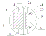
图2为本实用新型提出的政府公共服务满意度展示板的A部分结构示意图;Fig. 2 is the schematic diagram of the structure of part A of the government public service satisfaction display board proposed by the utility model;
图3为本实用新型提出的政府公共服务满意度展示板的B部分结构示意图。FIG. 3 is a schematic structural diagram of part B of the government public service satisfaction display board proposed by the present invention.
图中:1侧板、2固定孔、3移动座、4转动槽、5转动块、6展示板本体、7伸缩柱、8顶板、9智能摄像头、10太阳能电池板、11丝杆、12第一齿轮、13连接杆、14第二齿轮、15第一锥齿轮、16转动杆、17第二锥齿轮、18双轴电机、19蓄电池、20移动块、21卡块、22固定杆。In the picture: 1 side plate, 2 fixing holes, 3 moving seat, 4 rotating slot, 5 rotating block, 6 display board body, 7 telescopic column, 8 top plate, 9 smart camera, 10 solar panel, 11 screw rod, 12th A gear, 13 connecting rod, 14 second gear, 15 first bevel gear, 16 rotating rod, 17 second bevel gear, 18 biaxial motor, 19 battery, 20 moving block, 21 clamping block, 22 fixed rod.
具体实施方式Detailed ways
下面将结合本实用新型实施例中的附图,对本实用新型实施例中的技术方案进行清楚、完整地描述,显然,所描述的实施例仅仅是本实用新型一部分实施例,而不是全部的实施例。The technical solutions in the embodiments of the present utility model will be clearly and completely described below with reference to the accompanying drawings in the embodiments of the present utility model. Obviously, the described embodiments are only a part of the embodiments of the present utility model, rather than all the implementations. example.
实施例1Example 1
参照图1-3,政府公共服务满意度展示板,包括两个侧板1,两个侧板1相互靠近的一侧均开设有固定孔2,两个固定孔2内均滑动安装有移动座3,侧板1上设有驱动装置,驱动装置与两个移动座3相适配,两个移动座3相互靠近的一侧均开设有转动槽4,两个转动槽4内均转动安装有转动块5,两个转动块5相互靠近的一侧固定安装有同一个展示板本体6,展示板本体6的一侧固定安装有安装板,安装板上固定安装有刻度线板和多个伸缩柱7,展示板本体6的顶部固定安装有顶板8,顶板8的底部固定安装有智能摄像头9和WiFi路由器,顶板8的顶部固定安装有多个太阳能电池板10,两个侧板1相互靠近的一侧固定安装有同一个连接板,连接板的底部固定安装有蓄电池19和光伏逆变器,太阳能电池板10与光伏逆变器电性连接,光伏逆变器与蓄电池19电性连接。Referring to Figures 1-3, the government public service satisfaction display board includes two
本实施例中,驱动装置包括两个丝杆11、两个连接杆13和两个转动杆16,两个移动座3的顶部均开设有螺纹孔,丝杆11螺纹安装在对应的螺纹孔内,丝杆11的两端分别转动安装在固定孔2的两侧内壁上,两个丝杆11上均固定套设有第一齿轮12,两个侧板1相互远离的一侧均固定安装有安装座,连接杆13转动安装在对应的安装座上,两个连接杆13的顶端均固定安装有第二齿轮14,第二齿轮14与对应的第一齿轮12啮合,连接杆13带动第二齿轮14转动,第二齿轮14带动第一齿轮12转动,第一齿轮12带动丝杆11转动。In this embodiment, the driving device includes two
本实施例中,两个连接杆13的底端均固定安装有第一锥齿轮15,两个侧板1相互靠近的一侧均开设有转动孔,转动杆16转动安装在对应的转动孔内,两个转动杆16相互远离的一端均固定安装有第二锥齿轮17,第二锥齿轮17与对应的第一锥齿轮15啮合,连接板的顶部固定安装有双轴电机18,两个转动杆16相互靠近的一端分别固定安装在双轴电机18的两个输出轴上,双周电机18带动转动杆16转动,双周电机16带动第二锥齿轮17转动,第二锥齿轮17带动第一锥齿轮15转动。In this embodiment, the bottom ends of the two connecting
本实施例中,转动槽4的内壁上开设有环形槽,环形槽的内壁上开设有多个限位槽,转动块5的外侧焊接有移动块20,移动块20与环形槽的侧壁滑动连接,移动块20的一侧开设有压簧槽,压簧槽内滑动安装有卡块21,卡块21与限位槽相适配,卡块21上焊接有压簧的一端,压簧的另一端焊接在压簧槽的内壁上,展示板本体6带动转动块5在转动槽4内转动,转动块5带动移动块20在环形槽内滑动,移动块20带动卡块21移动。In this embodiment, an annular groove is formed on the inner wall of the
本实施例中,移动座3的顶部开设有通孔,通孔内滑动安装有固定杆22,固定杆22的两端分别焊接在固定孔2的两侧内壁上,连接板的底部固定安装有控制器,智能摄像头9、WiFi路由器和光伏逆变器均与控制器电性连接,移动座3移动时固定杆22被动在通孔内滑动,可以稳定移动座3移动时的位置,智能摄像头9可通过网络上传到服务器并将数据传输给用户,WiFi路由器可为展示板本体6附近的用户提供免费网络服务。In this embodiment, a through hole is formed on the top of the
实施例2Example 2
参照图1-3,在实施例1的基础上做了进一步改进:Referring to Figure 1-3, further improvements have been made on the basis of Embodiment 1:
政府公共服务满意度展示板,包括两个侧板1,两个侧板1相互靠近的一侧均开设有固定孔2,两个固定孔2内均滑动安装有移动座3,侧板1上设有驱动装置,驱动装置与两个移动座3相适配,两个移动座3相互靠近的一侧均开设有转动槽4,两个转动槽4内均转动安装有转动块5,两个转动块5相互靠近的一侧通过螺栓固定安装有同一个展示板本体6,展示板本体6的一侧通过螺栓固定安装有安装板,安装板上通过螺栓固定安装有刻度线板和多个伸缩柱7,展示板本体6的顶部通过螺栓固定安装有顶板8,顶板8的底部通过螺栓固定安装有智能摄像头9和WiFi路由器,顶板8的顶部通过螺栓固定安装有多个太阳能电池板10,两个侧板1相互靠近的一侧通过螺栓固定安装有同一个连接板,连接板的底部通过螺栓固定安装有蓄电池19和光伏逆变器,太阳能电池板10与光伏逆变器电性连接,光伏逆变器与蓄电池19电性连接。The government public service satisfaction display board includes two
本实施例中,驱动装置包括两个丝杆11、两个连接杆13和两个转动杆16,两个移动座3的顶部均开设有螺纹孔,丝杆11螺纹安装在对应的螺纹孔内,丝杆11的两端分别转动安装在固定孔2的两侧内壁上,两个丝杆11上均固定套设有第一齿轮12,两个侧板1相互远离的一侧均通过螺栓固定安装有安装座,连接杆13转动安装在对应的安装座上,两个连接杆13的顶端均通过螺栓固定安装有第二齿轮14,第二齿轮14与对应的第一齿轮12啮合,连接杆13带动第二齿轮14转动,第二齿轮14带动第一齿轮12转动,第一齿轮12带动丝杆11转动。In this embodiment, the driving device includes two
本实施例中,两个连接杆13的底端均通过螺栓固定安装有第一锥齿轮15,两个侧板1相互靠近的一侧均开设有转动孔,转动杆16转动安装在对应的转动孔内,两个转动杆16相互远离的一端均通过螺栓固定安装有第二锥齿轮17,第二锥齿轮17与对应的第一锥齿轮15啮合,连接板的顶部通过螺栓固定安装有双轴电机18,两个转动杆16相互靠近的一端分别通过螺栓固定安装在双轴电机18的两个输出轴上,双周电机18带动转动杆16转动,双周电机16带动第二锥齿轮17转动,第二锥齿轮17带动第一锥齿轮15转动。In this embodiment, the bottom ends of the two connecting
本实施例中,转动槽4的内壁上开设有环形槽,环形槽的内壁上开设有多个限位槽,转动块5的外侧焊接有移动块20,移动块20与环形槽的侧壁滑动连接,移动块20的一侧开设有压簧槽,压簧槽内滑动安装有卡块21,卡块21与限位槽相适配,卡块21上焊接有压簧的一端,压簧的另一端焊接在压簧槽的内壁上,展示板本体6带动转动块5在转动槽4内转动,转动块5带动移动块20在环形槽内滑动,移动块20带动卡块21移动。In this embodiment, an annular groove is formed on the inner wall of the
本实施例中,移动座3的顶部开设有通孔,通孔内滑动安装有固定杆22,固定杆22的两端分别焊接在固定孔2的两侧内壁上,连接板的底部通过螺栓固定安装有控制器,智能摄像头9、WiFi路由器和光伏逆变器均与控制器电性连接,移动座3移动时固定杆22被动在通孔内滑动,可以稳定移动座3移动时的位置,智能摄像头9可通过网络上传到服务器并将数据传输给用户,WiFi路由器可为展示板本体6附近的用户提供免费网络服务。In this embodiment, a through hole is formed on the top of the
本实施例中,由于设置了展示板本体6、伸缩柱7和智能摄像头9,通过拉伸伸缩柱7的长度,可以记录每次统计的数据,并参考刻度线板上的数据进行对比,可直观的观察每项指标的数据,智能摄像头9可通过网络上传到服务器并将数据传输给用户,WiFi路由器可为展示板本体6附近的用户提供免费网络服务,智能摄像头9的型号为LS-V8-720P,WiFi路由器的型号为MW325R,启动双轴电机18,双周电机18带动转动杆16转动,双周电机16带动第二锥齿轮17转动,第二锥齿轮17带动第一锥齿轮15转动,第一锥齿轮15带动连接杆13转动,连接杆13带动第二齿轮14转动,第二齿轮14带动第一齿轮12转动,第一齿轮12带动丝杆11转动,丝杆11带动移动座3在固定孔2内滑动,移动座3带动展示板本体6移动,即可调节展示板本体6的展示高度,转动展示板本体6,展示板本体6带动转动块5在转动槽4内转动,转动块5带动移动块20在环形槽内滑动,移动块20带动卡块21移动,卡块21移动到限位槽的位置后,因为压簧的弹性作用带动卡块21卡入限位槽内,即可暂时固定转动块5的位置,即可调节展示板本体6的展示角度,太阳能电池板10可将收集的电量通过光伏逆变器储存在蓄电池19内,蓄电池19为智能摄像头9、WiFi路由器和双轴电机18提供电源,可广泛用于政府日常服务工作中;本实用新型结构合理,操作方便,该展示板可直接调节伸缩柱7的长度并做成柱状图的样式进行展示,省时省力,且展示板能将每次统计的结果上传网络并进行公开,大大提高了政府公共服务能力和质量。In this embodiment, since the
以上所述,仅为本实用新型较佳的具体实施方式,但本实用新型的保护范围并不局限于此,任何熟悉本技术领域的技术人员在本实用新型揭露的技术范围内,根据本实用新型的技术方案及其实用新型构思加以等同替换或改变,都应涵盖在本实用新型的保护范围之内。The above description is only a preferred embodiment of the present invention, but the protection scope of the present invention is not limited to this. Equivalent replacement or modification of the new technical solution and its utility model concept shall be included within the protection scope of the present utility model.
Claims (3)
Priority Applications (1)
| Application Number | Priority Date | Filing Date | Title |
|---|---|---|---|
| CN201920981283.0U CN211319685U (en) | 2019-06-27 | 2019-06-27 | Government public service satisfaction display board |
Applications Claiming Priority (1)
| Application Number | Priority Date | Filing Date | Title |
|---|---|---|---|
| CN201920981283.0U CN211319685U (en) | 2019-06-27 | 2019-06-27 | Government public service satisfaction display board |
Publications (1)
| Publication Number | Publication Date |
|---|---|
| CN211319685U true CN211319685U (en) | 2020-08-21 |
Family
ID=72061448
Family Applications (1)
| Application Number | Title | Priority Date | Filing Date |
|---|---|---|---|
| CN201920981283.0U Expired - Fee Related CN211319685U (en) | 2019-06-27 | 2019-06-27 | Government public service satisfaction display board |
Country Status (1)
| Country | Link |
|---|---|
| CN (1) | CN211319685U (en) |
Cited By (1)
| Publication number | Priority date | Publication date | Assignee | Title |
|---|---|---|---|---|
| CN113129783A (en) * | 2021-04-29 | 2021-07-16 | 江苏建筑职业技术学院 | Rotatable advertisement showing stand |
-
2019
- 2019-06-27 CN CN201920981283.0U patent/CN211319685U/en not_active Expired - Fee Related
Cited By (2)
| Publication number | Priority date | Publication date | Assignee | Title |
|---|---|---|---|---|
| CN113129783A (en) * | 2021-04-29 | 2021-07-16 | 江苏建筑职业技术学院 | Rotatable advertisement showing stand |
| CN113129783B (en) * | 2021-04-29 | 2022-06-07 | 江苏建筑职业技术学院 | Rotatable advertisement showing stand |
Similar Documents
| Publication | Publication Date | Title |
|---|---|---|
| CN211319685U (en) | Government public service satisfaction display board | |
| CN209606768U (en) | A kind of VR pan-shot machine of angle adjustable | |
| CN213279903U (en) | Intelligent conference system | |
| CN210353819U (en) | Education and training are with books storage rack | |
| CN207047737U (en) | A kind of municipal construction warning sign for being easy to regulation | |
| CN206892485U (en) | A kind of miniature recorder glasses | |
| CN205565391U (en) | Transformer box convenient to electric wire netting is salvageed | |
| CN210805172U (en) | Wisdom display device of community | |
| CN214098760U (en) | Training set based on vocational training | |
| CN211294794U (en) | Dry-type transformer | |
| CN210837057U (en) | Decision display device for urban and rural planning | |
| CN209182749U (en) | One kind being based on Internet of things system intelligent interactive terminal | |
| CN210274919U (en) | Electronic intelligent class card management system | |
| CN207389866U (en) | A kind of LED electronic display storage boxes based on technology of Internet of things | |
| CN207883846U (en) | A kind of lithium battery tape sticking device | |
| CN218827570U (en) | Lithium battery device with base | |
| CN207742780U (en) | Sewage discharge monitoring warning device | |
| CN218771170U (en) | Bus duct for comprehensive wiring engineering | |
| CN211956734U (en) | Multifunctional teaching board for history teaching | |
| CN215341798U (en) | LED concatenation screen that installation is leveled and barrier propterty is good | |
| CN221842175U (en) | Assembled height Adjustable distribution box | |
| CN213028347U (en) | Network computer lab video monitoring device | |
| CN221378175U (en) | Integrated circuit design experiment box | |
| CN219627647U (en) | Portable folding photovoltaic power generation board | |
| CN214504649U (en) | Multifunctional network education training device |
Legal Events
| Date | Code | Title | Description |
|---|---|---|---|
| GR01 | Patent grant | ||
| GR01 | Patent grant | ||
| CF01 | Termination of patent right due to non-payment of annual fee | ||
| CF01 | Termination of patent right due to non-payment of annual fee |
Granted publication date: 20200821 |