CN211305822U - Fixing device for polishing glass - Google Patents
Fixing device for polishing glass Download PDFInfo
- Publication number
- CN211305822U CN211305822U CN201922484070.XU CN201922484070U CN211305822U CN 211305822 U CN211305822 U CN 211305822U CN 201922484070 U CN201922484070 U CN 201922484070U CN 211305822 U CN211305822 U CN 211305822U
- Authority
- CN
- China
- Prior art keywords
- top end
- fixing device
- bearing panel
- automatic telescopic
- glass
- Prior art date
- Legal status (The legal status is an assumption and is not a legal conclusion. Google has not performed a legal analysis and makes no representation as to the accuracy of the status listed.)
- Expired - Fee Related
Links
Images
Landscapes
- Grinding And Polishing Of Tertiary Curved Surfaces And Surfaces With Complex Shapes (AREA)
Abstract
The utility model relates to the technical field of glass processing equipment, in particular to a fixing device for polishing glass, which comprises a base, wherein a groove is arranged in the base, a bearing panel is fixed on the top end of the base, the bearing panel is provided with an opening with the same size as the groove, two sides of the bearing panel are provided with a suction layer notch, the bottom end of the suction layer notch is communicated with a dust removing device, the bottom wall in the base is provided with a chute, the chute is connected with a slide block in a sliding way, the top end of the slide block is provided with an automatic telescopic rod, the top end of the automatic telescopic rod is provided with a rotating device, the rotating device is provided with a support rod, the top end of the support rod is fixedly connected with a support plate matched with the groove, the support plate is uniformly fixed with a plurality of suckers, the back side of the top end, the device has simple structure and is convenient to operate and use.
Description
Technical Field
The utility model relates to a glass processing equipment technical field specifically is a glass polishes and uses fixing device.
Background
Glass belongs to the mixture, wide application in the building, be used for separating wind printing opacity, in process of production, good plate glass edge is very sharp after just cutting, need polish glass's edge, just can use, current fixing device, can't carry out the displacement to glass, adjust to a position that makes the staff comfortable, at the glass in-process of polishing, glass takes place to slide very easily, bring inconvenience for the work of polishing, can produce a large amount of cuttings at the in-process of polishing, these cuttings have not only polluted the environment, produce the injury to the human body, these cuttings adsorb the precision that the glass polished in the glass surface has produced the influence simultaneously, therefore we propose a glass and polish and use fixing device to solve above-mentioned problem.
SUMMERY OF THE UTILITY MODEL
This patent introduces a glass polishes and uses fixing device to solve fixing device and can't carry out the displacement to glass, adjust to the position that makes the staff comfortable, at the glass in-process of polishing, glass takes place to slide very easily, brings inconvenience for the work of polishing, can produce a large amount of cuttings at the in-process of polishing, and these cuttings have not only polluted the environment, produce the injury to the human body, and these cuttings adsorb the problem that has produced the influence to the precision that glass polished at the glass surface simultaneously.
In order to achieve the above object, the utility model provides a following technical scheme: the utility model provides a glass polishes and uses fixing device, includes the base, the base is provided with the recess in for, be fixed with the bearing panel on the top of base, be provided with the opening of recess equidimension on the bearing panel, the bearing panel both sides are provided with inhales the layer notch, the bottom intercommunication of inhaling the layer notch has dust collector, be provided with the spout on the inside diapire of base, sliding connection has the slider on the spout, the top of slider is provided with automatic telescopic link, the top of automatic telescopic link is provided with rotary device, the last bracing piece that is provided with of rotary device, the top fixedly connected with and the recess assorted layer board of bracing piece, the layer board evenly is fixed with a plurality of sucking discs, the top rear side of bearing panel is provided with L type backup pad, be provided with the pressure solid device in the.
Preferably, dust collector includes negative pressure air fan, the negative pressure air fan port is equipped with the aspiration channel, the one end intercommunication that negative pressure air fan was kept away from to the aspiration channel has the collection bits case, the top of collection bits case is equipped with the wind-collecting cover, the wind-collecting cover runs through bearing panel and connects the suction layer notch, be equipped with the filter screen in the aspiration channel.
Preferably, the rotating device comprises a motor, the motor is provided with a top end of a connecting rod fixedly connected with the automatic telescopic rod, the output end of the motor is fixedly connected with a rotating roller, the rotating roller is fixedly connected with a first gear, the top end of the automatic telescopic rod is provided with a second gear matched with a first gear in a wheel groove, a bearing is arranged in the second gear, the bearing is connected with the top end of the automatic telescopic rod, and the bottom end is connected with the second gear and a supporting rod.
Preferably, the pressing and fixing device comprises an air cylinder, the air cylinder is fixedly connected to the L-shaped supporting plate, an expansion rod is fixedly connected to the output end of the air cylinder, a pressing plate which is the same as the supporting plate in size is fixed to the bottom end of the expansion rod, and a rubber pad is arranged at the bottom end of the pressing plate.
Preferably, the right side of slider is equipped with electric putter, electric putter's bottom mounting is in recess right side inner wall.
Preferably, a moving groove matched with the L-shaped supporting plate is formed in the rear side of the top end of the bearing panel.
Compared with the prior art, the beneficial effects of the utility model are that:
this fixing device for glass is polished can be automatic inhale collection bits incasement with the cuttings that glass produced when polishing through starting negative pressure formula fan, avoids the cuttings to produce the influence to the precision that glass polished when the environmental protection, and the jar is passed through to the gas, can make the clamp plate shift up or move down and press admittedly to glass, presses the fastening to glass through the rubber pad and has fine guard action to glass when having fine guard action, prevents that the glass surface from crushing.
Drawings
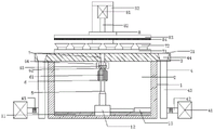
Fig. 1 is the utility model discloses glass polishes and uses fixing device major structure sketch map.
In the figure: the device comprises a base 1, a sliding chute 11, a sliding block 12, an electric push rod 13, a groove 2, a bearing panel 3, a suction layer notch 31, a 32L-shaped supporting plate, a dust removal device 4, a negative pressure fan 41, an air suction pipeline 42, a scrap collecting box 43, an air collecting cover 44, a filter screen 45, an automatic expansion rod 5, a rotating device 6, a motor 61, a rotating roller 62, a first gear 63, a second gear 64, a supporting rod 7, a supporting plate 71, a sucking disc 72, a pressing device 8, an air cylinder 81, an expansion rod 82, a pressing plate 83 and a rubber pad 84.
Detailed Description
The technology in the embodiment of the present invention will be described below with reference to the accompanying drawings in the embodiment of the present invention
The embodiments are clearly and completely described, and it is to be understood that the embodiments described are merely part of the present invention
Sub-embodiments, rather than all embodiments. Based on the embodiment in the utility model, it is ordinary in the art
All other embodiments obtained by the skilled person without making creative efforts belong to the present invention
The utility model discloses the scope of protection.
Referring to fig. 1, the present invention provides a fixing device for polishing glass: the automatic telescopic rod comprises a base 1, a groove 2 is arranged in the base 1, a bearing panel 3 is fixed on the top end of the base 1, an opening with the same size as the groove 2 is arranged on the bearing panel 3, suction layer notches 31 are arranged on two sides of the bearing panel 3, a dust removal device 4 is communicated with the bottom end of each suction layer notch 31, the dust removal device 4 is used for removing waste residues on the bearing panel 3 through the suction layer notches 31, a sliding groove 11 is arranged on the bottom wall inside the base 1, a sliding block 12 is connected on the sliding groove 11 in a sliding manner, an automatic telescopic rod 5 is arranged at the top end of the sliding block 12, the sliding block 12 slides in the sliding groove 11 so as to drive the automatic telescopic rod 5, a rotating device 6 is arranged at the top end of the automatic telescopic rod 5, the automatic telescopic rod 5 adopts a telescopic hollow cylindrical rod formed by rolling a metal strip or a plastic sheet, thereby have the self-tightening function, make the layer of curling have the elastic potential energy of exerting pressure to the telescopic link all the time, the rationale is that the rotary motion who utilizes screw motor becomes linear motion, can start automatic telescopic link 5, reciprocate rotary device 6, be provided with bracing piece 7 on the rotary device 6, the top fixedly connected with and recess 2 assorted layer board 71 of bracing piece 7, support layer board 71 through bracing piece 7, can place the glass of treating polishing on layer board 71, layer board 71 evenly is fixed with a plurality of sucking discs 72, the glass of treating polishing is fixed with the adsorptivity of sucking disc 72, the top rear side of bearing panel 3 is provided with L type backup pad 32, be provided with pressure solid device 8 on the L type backup pad 32, it fixes to extrude the glass top surface through pressure solid device 8.
Referring to fig. 1, the dust removing device 4 includes a negative pressure fan 41, an air suction pipeline 42 is arranged at a port of the negative pressure fan 41, one end of the air suction pipeline 42, which is far away from the negative pressure fan 41, is communicated with a scrap collecting box 43, an air collecting cover 44 is arranged at the top end of the scrap collecting box 43, the air collecting cover 44 penetrates through the bearing panel 3 and is connected with the suction layer notch 31, a filter screen 45 is arranged in the air suction pipeline 42, the negative pressure fan 41 utilizes the cooling principle of air convection and negative pressure ventilation, and can automatically suck scraps generated during glass polishing into the scrap collecting box 43, thereby protecting the environment and avoiding the influence of the scraps on the glass polishing precision, and in order to prevent the scraps from entering the negative pressure fan 41, the filter screen 45 is specially arranged to block the scraps, so as.
Referring to fig. 1, the rotating device 6 includes a motor 61, the motor 61 is provided with a top end of a connecting rod fixedly connected with the automatic telescopic rod 5, the output end of the motor 61 is fixedly connected with a rotating roller 62, the top of the motor 61 is connected with the rotating roller 62 through a speed reducer, a first gear 63 is fixedly connected with the rotating roller 62, the top end of the automatic telescopic rod 5 is provided with a second gear 64 matched with a wheel groove on the first gear 63, a bearing is arranged in the second gear 64, the bearing is connected with the top end of the automatic telescopic rod 5, the bottom end is connected with a supporting rod 7 through the second gear 64, the motor 61 is started, the rotating roller 62 rotates, the first gear 63 rotates, and therefore the second gear 64 rotates and the second gear.
Referring to fig. 1, the press-fixing device 8 includes a cylinder 81, the cylinder 81 is fixedly connected to the L-shaped support plate 32, an expansion rod 82 is fixedly connected to an output end of the cylinder 81, a pressing plate 83 having the same size as the support plate 71 is fixed to a bottom end of the expansion rod 82, a rubber pad 84 is arranged at a bottom end of the pressing plate 83, the cylinder 81 guides a cylindrical metal machine member in which a piston linearly reciprocates, air expands in an engine cylinder to convert heat energy into mechanical energy, air is compressed by the piston in a compressor cylinder to increase pressure, the cylinder 81 is started to enable the pressing plate 83 to move up or down to press and fix glass, and the rubber pad 84 has a good protection effect on glass when the glass is pressed and fixed, so that the glass surface is prevented from being.
Referring to fig. 1, an electric push rod 13 is disposed on the right side of the sliding block 12, the bottom end of the electric push rod 13 is fixed to the inner wall of the right side of the groove 2, the electric push rod 13 is an electric driving device for converting the rotation motion of the motor into the linear reciprocating motion of the push rod, and can be used as an execution machine in various simple or complex processes to realize remote control, centralized control or automatic control, and the sliding block 12 can be pushed left and right by starting the electric push rod 13 to adjust the position of the supporting plate 71.
Referring to fig. 1, a moving groove matched with the L-shaped supporting plate 32 is disposed on the rear side of the top end of the bearing panel 3, the L-shaped supporting plate 32 is moved left and right by the moving groove, the position of the pressing plate 83 can be adjusted, and the supporting plate 71 can be rotated horizontally by the rotating device 6.
The working principle is as follows: when the glass polishing device is used, glass to be polished is placed on the supporting plate 71, the supporting plate 71 is uniformly fixed with a plurality of suckers 72, the glass to be polished is fixed by utilizing the adsorbability of the suckers 72, the automatic telescopic rod 5 is started, the supporting plate 71 is lifted to a height which makes a worker comfortable, the air cylinder 81 is started, the pressing plate 83 can be moved upwards or downwards to press and fix the glass, the glass is well protected when being pressed and fixed through the rubber pad 84, the surface of the glass is prevented from being crushed, the electric push rod 13 is started to slide the sliding block 12 leftwards and rightwards, the position of the supporting plate 71 is transversely adjusted, the L-shaped supporting plate 32 is moved leftwards and rightwards through the moving groove, the position of the pressing plate 83 can be transversely adjusted, then polishing is carried out, powder scraps generated when the glass is polished can be automatically sucked into the powder collecting box 43 by starting the negative pressure fan 41, the environment is protected, and, in order to prevent the waste chips from entering the negative pressure fan 41, a filter screen 45 is specially arranged to block the waste chips to protect the negative pressure fan 41, after polishing is completed, the motor 61 can be started, the rotating roller 62 rotates to enable the first gear 63 to rotate, the second gear 64 is driven to rotate, the L-shaped supporting plate 32 is driven to move left and right through the moving groove, the supporting plate 71 rotates without obstacles, and the edge of the glass which is not polished is aligned with the polisher.
Although embodiments of the present invention have been shown and described, it will be appreciated by those skilled in the art that changes, modifications, substitutions and alterations can be made in these embodiments without departing from the principles and spirit of the invention, the scope of which is defined in the appended claims and their equivalents.
Claims (6)
1. The utility model provides a glass polishes and uses fixing device, includes base (1), its characterized in that: the base (1) is internally provided with a groove (2), a bearing panel (3) is fixed on the top end of the base (1), the bearing panel (3) is provided with an opening with the same size as the groove (2), two sides of the bearing panel (3) are provided with a layer suction notch (31), the bottom end of the layer suction notch (31) is communicated with a dust removal device (4), the bottom wall inside the base (1) is provided with a chute (11), the chute (11) is connected with a sliding block (12) in a sliding manner, the top end of the sliding block (12) is provided with an automatic telescopic rod (5), the top end of the automatic telescopic rod (5) is provided with a rotating device (6), the rotating device (6) is provided with a support rod (7), the top end of the support rod (7) is fixedly connected with a support plate (71) matched with the groove (2), and the support plate (71) is uniformly fixed, an L-shaped supporting plate (32) is arranged on the rear side of the top end of the bearing panel (3), and a pressing device (8) is arranged on the L-shaped supporting plate (32).
2. The fixing device for polishing glass according to claim 1, wherein: dust collector (4) include negative pressure air fan (41), negative pressure air fan (41) port is equipped with air suction pipeline (42), the one end intercommunication that negative pressure air fan (41) were kept away from in air suction pipeline (42) has collection bits case (43), the top of collection bits case (43) is equipped with air-collecting cover (44), air-collecting cover (44) run through load-bearing panel (3) and connect suction layer notch (31), be equipped with filter screen (45) in air suction pipeline (42).
3. The fixing device for polishing glass according to claim 1, wherein: rotating device (6) includes motor (61), be equipped with the top of the automatic telescopic link of connecting rod fixed connection (5) on motor (61), the rotatory roller of output fixedly connected with (62) of motor (61), fixedly connected with gear (63) on rotatory roller (62), the top of automatic telescopic link (5) is equipped with two (64) of gear that match with gear (63) last race, be equipped with the bearing in two (64) of gear, the top of bearing and automatic telescopic link (5) is connected, the bottom is connected in two (64) of gear and bracing piece (7).
4. The fixing device for polishing glass according to claim 1, wherein: the pressing and fixing device (8) comprises an air cylinder (81), the air cylinder (81) is fixedly connected onto the L-shaped supporting plate (32), an expansion rod (82) is fixedly connected to the output end of the air cylinder (81), a pressing plate (83) which is the same as the supporting plate (71) in size is fixed at the bottom end of the expansion rod (82), and a rubber pad (84) is arranged at the bottom end of the pressing plate (83).
5. The fixing device for polishing glass according to claim 1, wherein: the right side of slider (12) is equipped with electric putter (13), the bottom mounting in recess (2) right side inner wall of electric putter (13).
6. The fixing device for polishing glass according to claim 1, wherein: the rear side of the top end of the bearing panel (3) is provided with a moving groove matched with the L-shaped supporting plate (32).
Priority Applications (1)
| Application Number | Priority Date | Filing Date | Title |
|---|---|---|---|
| CN201922484070.XU CN211305822U (en) | 2019-12-31 | 2019-12-31 | Fixing device for polishing glass |
Applications Claiming Priority (1)
| Application Number | Priority Date | Filing Date | Title |
|---|---|---|---|
| CN201922484070.XU CN211305822U (en) | 2019-12-31 | 2019-12-31 | Fixing device for polishing glass |
Publications (1)
| Publication Number | Publication Date |
|---|---|
| CN211305822U true CN211305822U (en) | 2020-08-21 |
Family
ID=72064310
Family Applications (1)
| Application Number | Title | Priority Date | Filing Date |
|---|---|---|---|
| CN201922484070.XU Expired - Fee Related CN211305822U (en) | 2019-12-31 | 2019-12-31 | Fixing device for polishing glass |
Country Status (1)
| Country | Link |
|---|---|
| CN (1) | CN211305822U (en) |
Cited By (1)
| Publication number | Priority date | Publication date | Assignee | Title |
|---|---|---|---|---|
| CN114918776A (en) * | 2022-07-19 | 2022-08-19 | 江苏金圣硅基新材料研究院有限公司 | Glass processing platform of single round edge edging machine |
-
2019
- 2019-12-31 CN CN201922484070.XU patent/CN211305822U/en not_active Expired - Fee Related
Cited By (1)
| Publication number | Priority date | Publication date | Assignee | Title |
|---|---|---|---|---|
| CN114918776A (en) * | 2022-07-19 | 2022-08-19 | 江苏金圣硅基新材料研究院有限公司 | Glass processing platform of single round edge edging machine |
Similar Documents
| Publication | Publication Date | Title |
|---|---|---|
| CN212918909U (en) | Automatic burnishing device of artificial synthetic stone | |
| CN211305822U (en) | Fixing device for polishing glass | |
| CN212611162U (en) | Dust removal mechanism for textile machinery processing production | |
| CN109397386A (en) | A kind of construction site board cutting machine | |
| CN212495437U (en) | Horizontal lathe is used in production of colloid mill | |
| CN215036121U (en) | Edge grinding device for glass curtain wall machining | |
| CN214025018U (en) | Grinding device is used in turning production and processing | |
| CN214419202U (en) | Wall body fluting safety control positioner | |
| CN215036035U (en) | Accurate grinding device is used in machine part processing | |
| CN113770434A (en) | Milling machine with scrap iron cleaning function | |
| CN216633818U (en) | Three-roller adjustment driving type grinding machine | |
| CN219967357U (en) | Metal workpiece plane grinding machine | |
| CN217596682U (en) | Strip steel surface grinding device | |
| CN217255381U (en) | Dehumidification and dust removal equipment for ceramic material processing | |
| CN212977778U (en) | Polishing device for lamp panel machining | |
| CN219337149U (en) | Motor rotor's processingequipment | |
| CN214489752U (en) | Architectural decoration drilling positioner | |
| CN219076148U (en) | Dust fall cutting machine for stone material processing | |
| CN218801055U (en) | Composite board polishing equipment with cleaning function | |
| CN218534053U (en) | Burnishing machine of metal product production usefulness | |
| CN218053073U (en) | Detachable waterproof cupboard panel cutting device | |
| CN219541205U (en) | Dust collector is used in graphite processing | |
| CN217914487U (en) | Edge grinding machine | |
| CN211681383U (en) | Compaction grinding device of panel beating | |
| CN213766214U (en) | Dustproof effectual furniture processing is with planing machine |
Legal Events
| Date | Code | Title | Description |
|---|---|---|---|
| GR01 | Patent grant | ||
| GR01 | Patent grant | ||
| CF01 | Termination of patent right due to non-payment of annual fee | ||
| CF01 | Termination of patent right due to non-payment of annual fee |
Granted publication date: 20200821 Termination date: 20211231 |