CN211296474U - High-efficiency heat dissipation type permanent magnet motor shell - Google Patents
High-efficiency heat dissipation type permanent magnet motor shell Download PDFInfo
- Publication number
- CN211296474U CN211296474U CN201922141985.0U CN201922141985U CN211296474U CN 211296474 U CN211296474 U CN 211296474U CN 201922141985 U CN201922141985 U CN 201922141985U CN 211296474 U CN211296474 U CN 211296474U
- Authority
- CN
- China
- Prior art keywords
- heat dissipation
- pipe
- fan
- permanent magnet
- air
- Prior art date
- Legal status (The legal status is an assumption and is not a legal conclusion. Google has not performed a legal analysis and makes no representation as to the accuracy of the status listed.)
- Active
Links
Images


Landscapes
- Motor Or Generator Cooling System (AREA)
Abstract
The utility model discloses a high-efficient heat dissipation formula permanent-magnet machine shell relates to motor technical field. The utility model discloses an outer casing and fan, the both sides of shell body rigid coupling respectively have front end housing and interior end cap, the week side of shell body is personally submitted fan-shaped rigid coupling and is had a plurality of heat dissipation wings, the top rigid coupling of shell body has the heat dissipation box, the both ends of heat dissipation box link up respectively and are fixed with out tuber pipe and air-supply line, the one end of going out tuber pipe and air-supply line all link up and is fixed with an album tuber pipe, the inboard fixed intercommunication of collection tuber pipe has a plurality of ventilation pipes, the one end and the fixed intercommunication of shell body of ventilation pipe, the fan passes through. The utility model discloses a collection tuber pipe, heat dissipation box and fan can send into the inside hot gas flow of motor inside the heat dissipation box through the circulation of ventilation chamber, and the heat dissipation box cools off the heat flow, and the heat dissipation wing can play supplementary radiating effect.
Description
Technical Field
The utility model belongs to the technical field of the motor, especially, relate to a permanent-magnet machine shell.
Background
The motor is an electromagnetic device for realizing electric energy conversion or transmission according to the electromagnetic induction law, the motor is represented by a letter M (old standard is represented by D) in a circuit, the motor mainly has the function of generating driving torque and is used as a power source of electrical appliances or various machines, the generator is represented by a letter G in the circuit, and the motor mainly has the function of converting mechanical energy into electric energy.
Permanent magnet machine extensively is used for modern industry, agriculture even business field, along with the progress of science and technology, the continuous renewal of motor, however, present permanent magnet machine still has the poor problem of radiating effect, current permanent magnet machine generally mainly relies on the fin on the motor housing to increase heat radiating area to reach radiating effect, but this kind of heat dissipation mode when the motor is operated under rated power for a long time, can not in time quick dispel the heat that the motor produced, cause the inside heat accumulation of motor, lead to the motor to burn easily.
Therefore, the utility model designs a high-efficient heat dissipation formula permanent-magnet machine shell to solve above-mentioned problem.
SUMMERY OF THE UTILITY MODEL
An object of the utility model is to provide a high-efficient heat dissipation formula permanent magnet motor shell can send into the inside hot gas flow of motor inside the heat dissipation box through the circulation of ventilation chamber through collection tuber pipe, heat dissipation box and fan inside, and the heat dissipation box cools off the heat dissipation to the hot gas flow, and the heat dissipation wing can play supplementary radiating effect, has solved current motor shell and can not in time quick dispel the heat that produces the motor, causes the inside heat accumulation of motor, leads to the motor problem of burning out easily.
In order to solve the technical problem, the utility model discloses a realize through following technical scheme:
the utility model relates to a high-efficiency heat dissipation type permanent magnet motor shell, which comprises a shell body and a fan, wherein a rotor and a stator core are arranged inside the shell body, and a rotating shaft is arranged inside the rotor;
the heat dissipation device comprises an outer shell, a fan-shaped fixing strip, a heat dissipation box, a front end cover, an inner end cover, a fan-shaped fixing strip, a fan-shaped heat dissipation fin, a fan-shaped fixing strip, a fan-shaped heat dissipation box and a fan-shaped heat dissipation box, wherein the front end cover and the inner end cover are fixedly connected to two sides of the outer shell respectively;
an air outlet pipe and an air inlet pipe are respectively fixed at two ends of the heat dissipation box in a penetrating manner, air collecting pipes are respectively fixed at one ends of the air outlet pipe and the air inlet pipe in a penetrating manner, a plurality of ventilation pipes are fixedly communicated with the inner side of each air collecting pipe, one ends of the ventilation pipes are fixedly communicated with the outer shell, and the fan is fixedly installed inside the heat dissipation box through a support;
four ventilation cavities are formed between the inner side face of the outer shell and the stator iron core.
Further, every group the inside of fixed strip is formed with an installation groove, stator core's week side personally submits fan-shaped rigid coupling and has four lugs, the lug is located inside the installation groove.
Furthermore, the wind collecting pipe is an annular round pipe, and the fan is electrically connected with the internal wiring of the motor junction box.
Furthermore, two ends of the rotating shaft respectively penetrate through the front end cover and the inner end cover.
Furthermore, the shell body and the heat dissipation fins are all members made of aluminum alloy materials, and the ventilation pipe, the air collecting pipe, the air inlet pipe, the air outlet pipe and the heat dissipation box are all members made of metal copper materials.
The utility model discloses following beneficial effect has: the utility model discloses a collection tuber pipe, heat dissipation box and fan can send into the inside hot gas flow of motor inside the heat dissipation box through the circulation of ventilation chamber, and the ventilation pipe of metal copper product matter, collection tuber pipe, air-supply line, play tuber pipe and heat dissipation box cool off the heat dissipation to the hot gas flow, and the heat dissipation wing can play supplementary radiating effect.
Of course, it is not necessary for any particular product to achieve all of the above-described advantages at the same time.
Drawings
In order to more clearly illustrate the technical solutions of the embodiments of the present invention, the drawings used in the description of the embodiments will be briefly introduced below, and it is obvious that the drawings in the following description are only some embodiments of the present invention, and it is obvious for those skilled in the art that other drawings can be obtained according to these drawings without creative efforts.
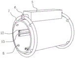
Fig. 1 is a schematic structural view of a high-efficiency heat dissipation type permanent magnet motor casing according to the present invention;
fig. 2 is a schematic view of the internal structure of the rotor and stator core of the present invention during assembly;
fig. 3 is a cross-sectional view of the present invention when assembled with a rotor and stator core;
fig. 4 is a schematic structural diagram of the outer casing of the present invention;
in the drawings, the components represented by the respective reference numerals are listed below:
1-outer shell, 2-front end cover, 3-inner end cover, 4-rotating shaft, 5-heat dissipation box, 6-air outlet pipe, 7-air collection pipe, 8-ventilation pipe, 9-rotor, 10-ventilation cavity, 11-fan, 12-fixing strip, 13-fixing plate, 14-heat dissipation fin, 15-air inlet pipe and 16-stator iron core.
Detailed Description
The technical solutions in the embodiments of the present invention will be described clearly and completely with reference to the accompanying drawings in the embodiments of the present invention, and it is obvious that the described embodiments are only some embodiments of the present invention, not all embodiments. Based on the embodiments of the present invention, all other embodiments obtained by a person of ordinary skill in the art without creative efforts belong to the protection scope of the present invention.
Referring to fig. 1-4, the present invention relates to a high-efficiency heat dissipation type permanent magnet motor casing, which comprises a casing body 1 and a fan 11, wherein a rotor 9 and a stator core 16 are arranged inside the casing body 1, and a rotating shaft 4 is arranged inside the rotor 9;
a front end cover 2 and an inner end cover 3 are fixedly connected to two sides of an outer shell 1 respectively, a plurality of radiating fins 14 are fixedly connected to the peripheral side surface of the outer shell 1 in a fan shape, four groups of fixing strips 12 are fixedly connected to the inner side surface of the outer shell 1 in a fan shape, an installation plate is fixedly connected to two sides of each group of fixing strips 12, and a radiating box 5 is fixedly connected to the top of the outer shell 1;
the both ends of heat dissipation box 5 link up respectively and are fixed with out tuber pipe 6 and air-supply line 15, and the one end that goes out tuber pipe 6 and air-supply line 15 all link up and is fixed with collection tuber pipe 7, and the inboard fixed intercommunication of collection tuber pipe 7 has a plurality of ventilation pipes 8, and the one end and the fixed intercommunication of shell body 1 of ventilation pipe 8, and fan 11 passes through support fixed mounting in the inside of heat dissipation box 5.
Four ventilation chambers 10 are formed between the inner side surface of the outer housing 1 and the stator core 16.
As shown in fig. 1, the wind collecting pipe 7 is an annular circular pipe, the fan 11 is electrically connected to the internal wiring of the motor junction box, two ends of the rotating shaft 4 respectively penetrate through the front end cover 2 and the inner end cover 3, the outer shell 1 and the heat dissipation fins 14 are all members made of aluminum alloy, and the ventilation pipe 8, the wind collecting pipe 7, the air inlet pipe 15, the air outlet pipe 6 and the heat dissipation box 5 are all members made of metal copper.
As shown in fig. 2, a mounting groove is formed inside each group of fixing strips 12, four protruding blocks are fixedly connected to the circumferential surface of the stator core 16 in a fan shape, and the protruding blocks are located inside the mounting groove.
One specific application of this embodiment is: after the motor is started, because the fan 11 is electrically connected with the internal wiring of the motor junction box, the fan 11 can be started along with the motor, under the action of the fan 11, the hot airflow in the ventilation cavity 10 can be collected into the air collecting pipe 7 through the ventilation pipe 8, finally enters the heat dissipation box 5 through the air inlet pipe 15, the airflow after heat dissipation and cooling enters the air collecting pipe 7 at the other end again through the air outlet pipe 6, and flows back to the ventilation cavity 10 through the ventilation pipe 8, the ventilation pipe 8 made of metal copper materials, the air collecting pipe 7, the air inlet pipe 15, the air outlet pipe 6 and the heat dissipation box 5 are used for heat dissipation and cooling of the hot airflow, the heat dissipation fins 14 can play a role in assisting heat dissipation, and efficient and quick heat dissipation of the.
In the description herein, references to the description of "one embodiment," "an example," "a specific example," etc., mean that a particular feature, structure, material, or characteristic described in connection with the embodiment or example is included in at least one embodiment or example of the invention. In this specification, the schematic representations of the terms used above do not necessarily refer to the same embodiment or example. Furthermore, the particular features, structures, materials, or characteristics described may be combined in any suitable manner in any one or more embodiments or examples.
The preferred embodiments of the present invention disclosed above are intended only to help illustrate the present invention. The preferred embodiments are not intended to be exhaustive or to limit the invention to the precise embodiments disclosed. Obviously, many modifications and variations are possible in light of the above teaching. The embodiments were chosen and described in order to best explain the principles of the invention and its practical applications, to thereby enable others skilled in the art to best understand the invention for and utilize the invention. The present invention is limited only by the claims and their full scope and equivalents.
Claims (5)
1. The utility model provides a high-efficient heat dissipation formula permanent magnet motor shell, includes shell body (1), the inside of shell body (1) is equipped with rotor (9) and stator core (16), the inside of rotor (9) is equipped with pivot (4), its characterized in that: also comprises a fan (11);
a front end cover (2) and an inner end cover (3) are fixedly connected to two sides of the outer shell (1) respectively, a plurality of radiating fins (14) are fixedly connected to the peripheral side surface of the outer shell (1) in a fan shape, four groups of fixing strips (12) are fixedly connected to the inner side surface of the outer shell (1) in a fan shape, an installation plate is fixedly connected to two sides of each group of fixing strips (12), and a radiating box (5) is fixedly connected to the top of the outer shell (1);
an air outlet pipe (6) and an air inlet pipe (15) are respectively fixedly communicated with two ends of the heat dissipation box (5), an air collecting pipe (7) is fixedly communicated with one ends of the air outlet pipe (6) and the air inlet pipe (15), a plurality of ventilation pipes (8) are fixedly communicated with the inner side of the air collecting pipe (7), one ends of the ventilation pipes (8) are fixedly communicated with the outer shell (1), and the fan (11) is fixedly arranged in the heat dissipation box (5) through a support;
four ventilation cavities (10) are formed between the inner side face of the outer shell (1) and the stator iron core (16).
2. The casing of the efficient heat dissipation type permanent magnet motor according to claim 1, wherein a mounting groove is formed inside each group of the fixing bars (12), four convex blocks are fixedly connected to the circumferential side surface of the stator core (16) in a fan shape, and the convex blocks are located inside the mounting groove.
3. The casing of the efficient heat dissipation type permanent magnet motor as claimed in claim 1, wherein the air collection pipe (7) is an annular circular pipe, and the fan (11) is electrically connected with an internal wiring of a motor junction box.
4. A casing of a high efficiency heat dissipation type permanent magnet motor according to claim 1, wherein two ends of the rotating shaft (4) respectively penetrate through the front end cover (2) and the inner end cover (3).
5. The efficient heat dissipation type permanent magnet motor shell according to claim 1, wherein the shell body (1) and the heat dissipation fins (14) are both members made of aluminum alloy, and the ventilation pipe (8), the air collection pipe (7), the air inlet pipe (15), the air outlet pipe (6) and the heat dissipation box (5) are all members made of metal copper materials.
Priority Applications (1)
| Application Number | Priority Date | Filing Date | Title |
|---|---|---|---|
| CN201922141985.0U CN211296474U (en) | 2019-12-04 | 2019-12-04 | High-efficiency heat dissipation type permanent magnet motor shell |
Applications Claiming Priority (1)
| Application Number | Priority Date | Filing Date | Title |
|---|---|---|---|
| CN201922141985.0U CN211296474U (en) | 2019-12-04 | 2019-12-04 | High-efficiency heat dissipation type permanent magnet motor shell |
Publications (1)
| Publication Number | Publication Date |
|---|---|
| CN211296474U true CN211296474U (en) | 2020-08-18 |
Family
ID=72019049
Family Applications (1)
| Application Number | Title | Priority Date | Filing Date |
|---|---|---|---|
| CN201922141985.0U Active CN211296474U (en) | 2019-12-04 | 2019-12-04 | High-efficiency heat dissipation type permanent magnet motor shell |
Country Status (1)
| Country | Link |
|---|---|
| CN (1) | CN211296474U (en) |
Cited By (1)
| Publication number | Priority date | Publication date | Assignee | Title |
|---|---|---|---|---|
| CN110855081A (en) * | 2019-12-04 | 2020-02-28 | 江苏世隆电机有限公司 | High-efficiency heat dissipation type permanent magnet motor shell |
-
2019
- 2019-12-04 CN CN201922141985.0U patent/CN211296474U/en active Active
Cited By (1)
| Publication number | Priority date | Publication date | Assignee | Title |
|---|---|---|---|---|
| CN110855081A (en) * | 2019-12-04 | 2020-02-28 | 江苏世隆电机有限公司 | High-efficiency heat dissipation type permanent magnet motor shell |
Similar Documents
| Publication | Publication Date | Title |
|---|---|---|
| CN108667213B (en) | Follow-up heat dissipation shock attenuation motor | |
| CN102005860A (en) | Heat abstractor for high-power vertical-axis wind generating set | |
| CN211296474U (en) | High-efficiency heat dissipation type permanent magnet motor shell | |
| CN210007491U (en) | efficient heat dissipation motor | |
| CN110768414A (en) | Cooling structure of permanent magnet motor | |
| CN102185420A (en) | Cooling system of 2MW wind driven generator | |
| CN208806700U (en) | A kind of electric motor end cap | |
| CN107528423B (en) | Closed permanent magnet generator for small wind power generation | |
| CN110855081A (en) | High-efficiency heat dissipation type permanent magnet motor shell | |
| CN211655931U (en) | Motor waterproof case convenient to maintenance | |
| CN202978652U (en) | High-capacity brushless excitation system | |
| CN210111788U (en) | Efficient high-voltage generator wind path | |
| CN201985723U (en) | High-voltage variable frequency speed control three-phase asynchronous motor equipment | |
| CN213402732U (en) | Heat radiation structure of motor for electric tool | |
| CN212137477U (en) | High-speed permanent magnet synchronous motor | |
| CN115912728A (en) | High-efficiency synchronous motor | |
| CN210092988U (en) | Optimized heat dissipation type surface-mounted permanent magnet motor rotor and motor | |
| CN204992998U (en) | Self cooling PMSM of special power assisted steering of new energy automobile | |
| CN110649768B (en) | Alternating current generator | |
| CN208241420U (en) | Armature ventilation channel plate for direct current generator | |
| CN218217016U (en) | Small-size airtight permanent magnet generator for wind power generation | |
| CN217883125U (en) | Inner fan suitable for low-voltage high-power motor and low-voltage high-power motor | |
| CN213846412U (en) | Permanent magnet synchronous motor assembly structure | |
| CN218648691U (en) | Large-flow cold air down-pressing type motor | |
| CN104917349A (en) | Power-assisted steering high-efficiency high-reliability self-cooling permanent-magnet synchronous motor especially for new energy automobile |
Legal Events
| Date | Code | Title | Description |
|---|---|---|---|
| GR01 | Patent grant | ||
| GR01 | Patent grant |