CN211283573U - Special material lifting means of construction - Google Patents
Special material lifting means of construction Download PDFInfo
- Publication number
- CN211283573U CN211283573U CN201922047073.7U CN201922047073U CN211283573U CN 211283573 U CN211283573 U CN 211283573U CN 201922047073 U CN201922047073 U CN 201922047073U CN 211283573 U CN211283573 U CN 211283573U
- Authority
- CN
- China
- Prior art keywords
- guide rails
- hopper
- material lifting
- guide
- fixedly connected
- Prior art date
- Legal status (The legal status is an assumption and is not a legal conclusion. Google has not performed a legal analysis and makes no representation as to the accuracy of the status listed.)
- Expired - Fee Related
Links
Images


Abstract
The utility model belongs to the technical field of material lifting means, especially, be a special material lifting means of construction, it is unreasonable inadequately to current building material lifting means structure, the problem of material lifting efficiency low, the following scheme is put forward now, it includes the base and places the hopper in base top one side, four guide rails that are the rectangle distribution of top opposite side fixedly connected with of base, equal slidable mounting has first guide post in two guide rails that are close to the hopper in four guide rails, equal slidable mounting has the second guide post in two guide rails that keep away from the hopper in four guide rails, find between two first guide posts and be connected with same reel, around being equipped with the cable wire on the reel, the one end of cable wire and the top fixed connection of hopper. The utility model has the advantages of reasonable design, the material promotes steadily, efficient, the rational utilization hydraulic cylinder power is sufficient and the limited characteristics of migration range, low in manufacturing cost is honest and clean, is fit for using widely.
Description
Technical Field
The utility model relates to a material lifting means technical field especially relates to a special material lifting means of construction.
Background
The building construction refers to production activities in the engineering construction implementation stage, is the construction process of various buildings, and also can be a process of changing various lines on a design drawing into a real object at a specified place, and a large amount of building materials are required to be used as a foundation in the building construction process to carry out construction work, so that material lifting equipment is required to improve the material transfer efficiency. For example, chinese patent with publication number CN206680151U discloses a material lifting device special for building construction, which comprises a lighting bulb, a moving block, a lighting switch and an emergency stop, wherein a motor switch is arranged on the right side of a power switch, the lighting switch is arranged below the motor switch, and the lighting bulb, the lifting motor and the powerful dust collector are all electrically connected with a control panel. The powerful dust collector is installed, and the dust that produces of the in-process of the strong dust collector in-time absorption promotion material like this can keep the health around the equipment on the one hand, and on the other hand also is favorable to operating personnel's health, has installed lighting bulb, and when light was not good like this, this equipment also can normal work, has improved the performance of this equipment.
But above-mentioned design still has the shortcoming, and the building material lifting means structural design of above-mentioned patent design is not reasonable enough, and material lifting speed is relatively slow, is unfavorable for the use, therefore we have proposed a special material lifting means of construction and have been used for solving above-mentioned problem.
Disclosure of Invention
The utility model aims at solving the shortcoming that current building material lifting means structure is reasonable inadequately, material lifting efficiency is low, and the special material lifting means of construction that proposes.
In order to achieve the above purpose, the utility model adopts the following technical scheme:
a material lifting device special for building construction comprises a base and a hopper arranged on one side of the top of the base, wherein the other side of the top of the base is fixedly connected with four guide rails which are distributed in a rectangular shape, first guide posts are arranged in two guide rails which are close to the hopper in the four guide rails in a sliding manner, second guide posts are arranged in two guide rails which are far away from the hopper in the four guide rails in a sliding manner, the same reel is found and connected between the two first guide posts, a steel cable is wound on the reel, one end of the steel cable is fixedly connected with the top of the hopper, one side, close to each other, of the four guide rails is fixedly connected with the same supporting plate, the other end of the steel cable is fixedly connected with the supporting plate, one side, close to each other, of the first guide posts and the second guide posts is fixedly connected with two groups, and a piston shaft of the hydraulic oil cylinder is fixedly connected with the bottom of the slide rod.
Preferably, the one end of bracing piece is all welded in one side four corners of hopper frame guide rail, and the other end of bracing piece rotates and is connected with the pulley, and pulley slidable mounting is in two guide rails that are close to the hopper in four guide rails for the hopper can steady smooth and easy lift removal.
Preferably, the universal wheels are installed at four corners of the bottom of the base, and the top sides of the four guide rails are fixedly connected with the same top plate, so that the portability of the device is improved.
Preferably, both ends of the reel are fixedly connected with the supporting shafts, and both ends of the supporting shafts are respectively and fixedly connected to the corresponding first guide posts, so that the reel can be synchronously lifted along with the first guide posts.
Preferably, one side fixedly connected with that two slide bars are close to each other is a plurality of diagonal draw bars, and a plurality of diagonal draw bars are crisscross to be set up for non-deformable, can go up and down in step between two slide bars.
Preferably, the outer sides of the steel cable, the first guide post and the second guide post are coated with grease, so that the friction resistance of each part during operation is reduced.
The utility model discloses a special material lifting means of construction, the building material that will promote is placed in the hopper, starts hydraulic cylinder, utilizes hydraulic cylinder to promote the slide bar and upwards moves, and the both ends of slide bar drive first guide post and second guide post upwards to slide in the guide rail, and first guide post drives the reel through the back shaft and upwards moves, and the reel can upwards lift the cable wire at the central point;
the utility model discloses a special material lifting means of construction, because the both ends of cable wire are fixed connection respectively on hopper and backup pad, backup pad and guide rail keep stationary, can lift the hopper fast through the cable wire when the reel moves up, and the rise speed of hopper is twice of the rise speed of reel;
the utility model has the advantages of reasonable design, the material promotes steadily, efficient, the rational utilization hydraulic cylinder power is sufficient and the limited characteristics of migration range, low in manufacturing cost is honest and clean, is fit for using widely.
Drawings
Fig. 1 is a schematic structural view of a material lifting device special for building construction provided by the utility model;
fig. 2 is a schematic structural view of a part a of a special material lifting device for building construction provided by the utility model;
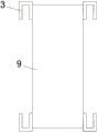
fig. 3 is the utility model provides a special material lifting means's of construction guide rail and the plan view of backup pad connecting piece.
In the figure: 1. a base; 2. a hopper; 3. a guide rail; 4. a first guide post; 5. a second guide post; 6. a reel; 7. a steel cord; 8. a slide bar; 9. a support plate; 10. a hydraulic cylinder; 11. a pulley; 12. a support bar; 13. a diagonal member; 14. a universal wheel; 15. a top plate; 16. and supporting the shaft.
Detailed Description
The technical solutions in the embodiments of the present invention will be described clearly and completely with reference to the accompanying drawings in the embodiments of the present invention, and it is obvious that the described embodiments are only some embodiments of the present invention, not all embodiments.
Referring to fig. 1-3, a material lifting device special for building construction comprises a base 1 and a hopper 2 arranged on one side of the top of the base 1, wherein the other side of the top of the base 1 is fixedly connected with four guide rails 3 which are distributed in a rectangular shape, first guide posts 4 are respectively and slidably arranged in two guide rails 3 which are close to the hopper 2 in the four guide rails 3, second guide posts 5 are respectively and slidably arranged in two guide rails 3 which are far away from the hopper 2 in the four guide rails 3, a same reel 6 is found and connected between the two first guide posts 4, a steel cable 7 is wound on the reel 6, one end of the steel cable 7 is fixedly connected with the top of the hopper 2, one side of the four guide rails 3 which are close to each other is fixedly connected with a same support plate 9, the other end of the steel cable 7 is fixedly connected with the support plate 9, and one side of the first guide posts 4 which is close, and the supporting plate 9 is positioned below the sliding rod 8, the top of the supporting plate 9 is fixedly provided with a hydraulic oil cylinder 10 through a bolt, the model of the hydraulic oil cylinder 10 is SZ-HSGL01E50/30-500, and the piston shaft of the hydraulic oil cylinder 10 is fixedly connected with the bottom of the sliding rod 8.
The utility model discloses in, the one end of bracing piece 12 is all welded in one side four corners of 2 frame guide rails 3 of hopper, and the other end of bracing piece 12 rotates and is connected with pulley 11, and pulley 11 slidable mounting is close to in two guide rails 3 of hopper 2 in four guide rails 3 for hopper 2 can steady smooth and easy lift removal.
The utility model discloses in, universal wheel 14 is all installed in base 1's bottom four corners, and the same roof 15 of top side fixedly connected with of four guide rails 3, improves the device's portability.
The utility model discloses in, the equal fixedly connected with back shaft 16 in both ends of reel 6, and the both ends of back shaft 16 fixed connection respectively is on corresponding first guide post 4 for reel 6 can be along with first guide post 4 synchronous lifting.
The utility model discloses in, two slide bars 8 one side fixedly connected with a plurality of diagonal draw bars 13 that are close to each other, and a plurality of diagonal draw bars 13 crisscross setting for non-deformable, can go up and down in step between two slide bars 8.
The utility model discloses in, the outside of cable wire 7, first guide post 4 and second guide post 5 all scribbles lubricating grease, the frictional resistance when reducing each part function.
In the utility model, when in use, a control switch is arranged for the hydraulic cylinder 10, the building material to be lifted is placed in the hopper 2, the hydraulic cylinder 10 is started, so that the piston shaft of the hydraulic oil cylinder 10 pushes the slide bar 8 to move upwards, at the moment, the two ends of the slide bar 8 drive the first guide post 4 and the second guide post 5 to slide upwards in the guide rail 3, the first guide post 4 drives the reel 6 to move upwards through the support shaft 16, the reel 6 can lift the steel cable 7 upwards at the central part, because the two ends of the steel cable 7 are respectively and fixedly connected with the hopper 2 and the supporting plate 9, and the supporting plate 9 and the guide rail 3 are kept fixed, therefore, when the reel 6 moves upwards, the hopper 2 can be quickly lifted by the steel rope 7, the lifting speed of the hopper 2 is twice of that of the reel 6, and the characteristics that the hydraulic oil cylinder 10 has sufficient power and the moving range is limited are reasonably utilized.
Claims (6)
1. The utility model provides a special material lifting means of construction, including base (1) and place hopper (2) in base (1) top one side, a serial communication port, the top opposite side fixedly connected with four guide rails (3) that are the rectangle and distribute of base (1), equal slidable mounting has first guide post (4) in two guide rails (3) that are close to hopper (2) among four guide rails (3), equal slidable mounting has second guide post (5) in two guide rails (3) that keep away from hopper (2) among four guide rails (3), find between two first guide posts (4) to be connected with same reel (6), the last cable wire (7) of having twined on reel (6), the one end of cable wire (7) and the top fixed connection of hopper (2), the one side fixedly connected with same backup pad (9) that four guide rails (3) are close to each other, the other end fixed connection of cable wire (7) is on backup pad (9), two sets of slide bars (8) of one side fixedly connected with that first guide post (4) and second guide post (5) are close to each other, and backup pad (9) are located the below of slide bar (8), and there are hydraulic cylinder (10) at the top of backup pad (9) through bolt fixed mounting, and the piston shaft of hydraulic cylinder (10) and the bottom fixed connection of slide bar (8).
2. The special material lifting equipment for building construction as claimed in claim 1, wherein one end of a support rod (12) is welded to each of four corners of one side of the frame guide rail (3) of the hopper (2), the other end of the support rod (12) is rotatably connected with a pulley (11), and the pulley (11) is slidably mounted in two guide rails (3) close to the hopper (2) in the four guide rails (3).
3. The special material lifting equipment for building construction as claimed in claim 1, wherein four corners of the bottom of the base (1) are all provided with universal wheels (14), and the top sides of the four guide rails (3) are fixedly connected with the same top plate (15).
4. The special material lifting equipment for building construction according to claim 1, characterized in that both ends of the reel (6) are fixedly connected with supporting shafts (16), and both ends of the supporting shafts (16) are respectively fixedly connected to the corresponding first guide posts (4).
5. The special material lifting equipment for building construction as claimed in claim 1, wherein one side of the two sliding rods (8) close to each other is fixedly connected with a plurality of diagonal draw bars (13), and the plurality of diagonal draw bars (13) are arranged in a staggered manner.
6. The special material lifting equipment for building construction as claimed in claim 1, wherein the outer sides of the steel cable (7), the first guide post (4) and the second guide post (5) are coated with grease.
Priority Applications (1)
| Application Number | Priority Date | Filing Date | Title |
|---|---|---|---|
| CN201922047073.7U CN211283573U (en) | 2019-11-25 | 2019-11-25 | Special material lifting means of construction |
Applications Claiming Priority (1)
| Application Number | Priority Date | Filing Date | Title |
|---|---|---|---|
| CN201922047073.7U CN211283573U (en) | 2019-11-25 | 2019-11-25 | Special material lifting means of construction |
Publications (1)
| Publication Number | Publication Date |
|---|---|
| CN211283573U true CN211283573U (en) | 2020-08-18 |
Family
ID=72031984
Family Applications (1)
| Application Number | Title | Priority Date | Filing Date |
|---|---|---|---|
| CN201922047073.7U Expired - Fee Related CN211283573U (en) | 2019-11-25 | 2019-11-25 | Special material lifting means of construction |
Country Status (1)
| Country | Link |
|---|---|
| CN (1) | CN211283573U (en) |
-
2019
- 2019-11-25 CN CN201922047073.7U patent/CN211283573U/en not_active Expired - Fee Related
Similar Documents
| Publication | Publication Date | Title |
|---|---|---|
| CN109019141B (en) | Optical fiber hoisting and laying device | |
| CN211283573U (en) | Special material lifting means of construction | |
| CN211245539U (en) | Special stage property lifting device for live-action stage | |
| CN210656027U (en) | Lifting machine | |
| CN208648628U (en) | A kind of movable tube lifting device | |
| CN209699583U (en) | A kind of drilling equipment for building block | |
| CN113353793A (en) | Shield segment lifting machine | |
| CN207434933U (en) | Workshop weight part lifting device | |
| CN206232382U (en) | For the air cylinder connecting rod formula lowering or hoisting gear of short stroke jacking equipment | |
| CN206417835U (en) | A kind of vehicle part snatch device | |
| CN218879319U (en) | Strutting arrangement for smart power grids | |
| CN215789014U (en) | High-efficient polishing equipment in door and window curtain surface | |
| CN204714474U (en) | A kind of transfer equipment | |
| CN218465409U (en) | Lifting device for bricklaying equipment | |
| CN219279107U (en) | Horizontal double-shaft wire winding machine | |
| CN213444708U (en) | Double-cylinder jacking rotating mechanism for inductor processing feeding | |
| CN213864722U (en) | Stringing construction device for installing intelligent power equipment | |
| CN214997799U (en) | Traction device for mining hydraulic support | |
| CN218088736U (en) | Mine hoist arresting gear | |
| CN203922508U (en) | A kind of Portable crane device | |
| CN212892578U (en) | Automatic framing machine | |
| CN210944632U (en) | Self-rope-arranging integrated suspender | |
| CN117263105B (en) | Lifting device for be used for photovoltaic board subassembly installation | |
| CN220056268U (en) | Electric screw rod operation vehicle | |
| CN218708614U (en) | Stacking crane for anode carbon block with rotatable fixture |
Legal Events
| Date | Code | Title | Description |
|---|---|---|---|
| GR01 | Patent grant | ||
| GR01 | Patent grant | ||
| CF01 | Termination of patent right due to non-payment of annual fee | ||
| CF01 | Termination of patent right due to non-payment of annual fee |
Granted publication date: 20200818 Termination date: 20211125 |