CN211283515U - Regularization platform that tower crane attaches wall - Google Patents
Regularization platform that tower crane attaches wall Download PDFInfo
- Publication number
- CN211283515U CN211283515U CN201921952366.3U CN201921952366U CN211283515U CN 211283515 U CN211283515 U CN 211283515U CN 201921952366 U CN201921952366 U CN 201921952366U CN 211283515 U CN211283515 U CN 211283515U
- Authority
- CN
- China
- Prior art keywords
- groove steel
- steel body
- butt joint
- guardrail
- joint groove
- Prior art date
- Legal status (The legal status is an assumption and is not a legal conclusion. Google has not performed a legal analysis and makes no representation as to the accuracy of the status listed.)
- Active
Links
Images


Abstract
The utility model discloses a regularization platform for a tower crane wall attachment, relating to the technical field of tower crane wall attachment tools; the bottom assembly table is a square body, a guardrail rod body is fixedly mounted at the upper end of the bottom assembly table, insertion blocks are fixedly mounted at two ends of an insertion groove steel body respectively and are inserted at two ends of a butt joint groove steel body respectively, mounting holes are formed in the butt joint groove steel body, locking bolts penetrate through the mounting holes and are connected into threaded holes of the insertion blocks, reinforcing plate bodies are fixedly mounted at the bottoms of the insertion groove steel body and the butt joint groove steel body, a plurality of guardrail fixing sleeves are fixedly mounted at the upper ends of the insertion groove steel body and the butt joint groove steel body, fixing screws are connected onto the outer side walls of the guardrail fixing sleeves, and platform plate bodies are welded onto the inner side walls of the insertion groove steel body and the butt joint groove steel body; the utility model can realize fast assembly and fast disassembly, has high stability and simultaneously improves the safety; simple structure, convenient to use, and the quick operation of being convenient for saves time.
Description
Technical Field
The utility model belongs to the technical field of the tower crane attaches the wall apparatus, concretely relates to tower crane attaches regularization platform of wall.
Background
The tower crane is the most common hoisting equipment on the construction site, also called tower crane, and is used for hoisting construction raw materials such as reinforcing steel bars, wood ridges, concrete, steel pipes and the like for construction by the extension (height) of one section and one section (called standard section for short). The tower crane is an indispensable device on a construction site. The tower crane (tower crane) tip has the function of bearing the upper load transmitted by the boom guy rope and the balance arm guy rope, and directly transmits the upper load to the tower body structure through the rotary tower, the rotary table, the bearing seat and other structural components. The self-elevating tower top is provided with a truncated cone column type, a forward-inclined or backward-inclined truncated cone column type, a herringbone frame type and an inclined support frame type.
The existing sizing platform for the tower crane wall attachment is inconvenient to assemble and disassemble when in use, and is low in strength, complex to operate and low in efficiency.
SUMMERY OF THE UTILITY MODEL
The problems that an existing shaped platform for a tower crane wall attachment is inconvenient to assemble and disassemble, low in strength, complex to operate and low in efficiency when in use are solved; an object of the utility model is to provide a tower crane attaches regularization platform of wall.
The utility model relates to a tower crane wall-attached stereotyped platform, which comprises a bottom assembly table and a guardrail rod body; the bottom assembly table is a cuboid, a guardrail rod body is fixedly mounted at the upper end of the bottom assembly table, and the bottom assembly table comprises an insertion groove steel body, a butt joint groove steel body, a reinforcing plate body, an insertion block, a locking bolt, a guardrail fixing sleeve and a fixing screw; the equal fixed mounting in both ends of the inserting groove steel body has the grafting piece, the grafting piece is pegged graft respectively at the both ends of the butt joint groove steel body, and seted up the mounting hole on the butt joint groove steel body, the locking bolt alternates in the mounting hole and is connected in the threaded hole of grafting piece, the inserting groove steel body, the bottom fixed mounting of the butt joint groove steel body has the reinforcing plate body, the inserting groove steel body, the upper end fixed mounting of the butt joint groove steel body has the fixed cover of several guardrail, be connected with the fixed screw on the lateral wall of the fixed cover of guardrail, the inserting groove steel body, the welding has the platform plate body on the inside wall of the butt joint groove.
Preferably, the upper surface of the platform plate body is provided with an anti-skid groove body.
Preferably, the guardrail rod body is formed by welding cross rods at the upper ends of a plurality of longitudinal rods, and the longitudinal rods are connected through connecting rods.
Preferably, the locking bolt is a reinforcing bolt.
Preferably, the outer side wall of the insertion block is provided with a wear-resistant layer.
Compared with the prior art, the beneficial effects of the utility model are that:
the rapid assembly and disassembly can be realized, the stability is high, and the safety is improved;
secondly, simple structure, convenient to use, and be convenient for quick operation, save time.
Drawings
For ease of illustration, the invention is described in detail by the following detailed description and accompanying drawings.
Fig. 1 is a schematic structural view of the present invention;
FIG. 2 is a schematic structural view of a middle bottom assembly table according to the present invention;
fig. 3 is a schematic structural view of the middle guard rail fixing sleeve of the utility model.
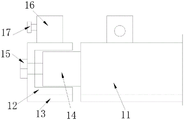
In the figure: 1-a bottom assembly station; 2-a guardrail rod body; 11-inserting groove steel body; 12-butting the channel steel body; 13-a reinforcement plate body; 14-a plug-in block; 15-locking bolts; 16-a guardrail fixing sleeve; 17-set screw.
Detailed Description
In order to make the objects, technical solutions and advantages of the present invention more apparent, the present invention will be described below with reference to specific embodiments shown in the accompanying drawings. It should be understood that the description is intended to be illustrative only and is not intended to limit the scope of the present invention. Moreover, in the following description, descriptions of well-known structures and techniques are omitted so as to not unnecessarily obscure the concepts of the present invention.
It should also be noted that, in order to avoid obscuring the invention with unnecessary details, only the structures and/or process steps that are closely related to the solution according to the invention are shown in the drawings, while other details that are not relevant to the invention are omitted.
As shown in fig. 1, 2 and 3, the following technical solutions are adopted in the present embodiment: comprises a bottom assembly table 1 and a guardrail rod body 2; the bottom assembly table 1 is a square body, the upper end of the bottom assembly table 1 is fixedly provided with a guardrail rod body 2, and the bottom assembly table 1 comprises an insertion groove steel body 11, a butt joint groove steel body 12, a reinforcing plate body 13, an insertion block 14, a locking bolt 15, a guardrail fixing sleeve 16 and a fixing screw 17; the equal fixed mounting in both ends of the inserting groove steel body 11 has inserting block 14, inserting block 14 pegs graft respectively at the both ends of the butt joint groove steel body 12, inserting groove steel body 11 can be realized in the grafting of inserting block, butt joint groove steel body 12, and realize quick fixed through locking bolt 15, it can realize quick fixed, and the later stage of being convenient for is dismantled, and seted up the mounting hole on the butt joint groove steel body 12, locking bolt 15 cross-under is in the mounting hole and is connected in inserting block 14's threaded hole, inserting groove steel body 11, the bottom fixed mounting to butt joint groove steel body 12 has reinforcing plate body 13, inserting groove steel body 11, the fixed cover 16 of several guardrail of upper end fixed mounting to groove steel body 12, be connected with fixed screw 17 on the lateral wall of the fixed cover 16 of guardrail, inserting groove steel body 11, the welding has the platform plate body on the inside wall of butt joint groove steel body 12.
Furthermore, an anti-skid groove body is arranged on the upper surface of the platform plate body.
Further, the guardrail body of rod 2 has the horizontal pole to constitute for the upper end welding of several vertical poles, connects through the connecting rod between the several vertical pole.
Further, the locking bolt 15 is a reinforcing bolt.
Further, the outer side wall of the insertion block 14 is provided with a wear-resistant layer.
The working principle of the specific embodiment is as follows: when using, through installing the guardrail body of rod 2 on bottom assembly station 1, fast assembly can be realized to its bottom assembly station 1, simultaneously when the equipment, peg graft the plug-in block 14 of the inserting groove steel body 11 in the cell body of butt joint groove steel body 12, then through locking bolt snap-on can, it can the installation time, and install back stability, and the guardrail body of rod snap-on can in the fixed cover 16 of guardrail, its later stage is also convenient to be dismantled, the guardrail body of rod passes through the set screw 17 to be installed in the fixed cover 16 of guardrail.
It is obvious to a person skilled in the art that the invention is not restricted to details of the above-described exemplary embodiments, but that it can be implemented in other specific forms without departing from the spirit or essential characteristics of the invention. The present embodiments are therefore to be considered in all respects as illustrative and not restrictive, the scope of the invention being indicated by the appended claims rather than by the foregoing description, and all changes which come within the meaning and range of equivalency of the claims are therefore intended to be embraced therein.
Furthermore, it should be understood that although the present description refers to embodiments, not every embodiment may contain only a single embodiment, and such description is for clarity only, and those skilled in the art should integrate the description, and the embodiments may be combined as appropriate to form other embodiments understood by those skilled in the art.
Claims (5)
1. The utility model provides a tower crane attaches regularization platform of wall which characterized in that: comprises a bottom assembly table and a guardrail rod body; the bottom assembly table is a cuboid, a guardrail rod body is fixedly mounted at the upper end of the bottom assembly table, and the bottom assembly table comprises an insertion groove steel body, a butt joint groove steel body, a reinforcing plate body, an insertion block, a locking bolt, a guardrail fixing sleeve and a fixing screw; the equal fixed mounting in both ends of the inserting groove steel body has the grafting piece, the grafting piece is pegged graft respectively at the both ends of the butt joint groove steel body, and seted up the mounting hole on the butt joint groove steel body, the locking bolt alternates in the mounting hole and is connected in the threaded hole of grafting piece, the inserting groove steel body, the bottom fixed mounting of the butt joint groove steel body has the reinforcing plate body, the inserting groove steel body, the upper end fixed mounting of the butt joint groove steel body has the fixed cover of several guardrail, be connected with the fixed screw on the lateral wall of the fixed cover of guardrail, the inserting groove steel body, the welding has the platform plate body on the inside wall of the butt joint groove.
2. The sizing platform for the tower crane wall according to claim 1, wherein: the upper surface of the platform plate body is provided with an anti-skidding groove body.
3. The sizing platform for the tower crane wall according to claim 1, wherein: the guardrail rod body is welded for the upper end of several vertical poles and is constituteed with the horizontal pole, connects through the connecting rod between the several vertical poles.
4. The sizing platform for the tower crane wall according to claim 1, wherein: the locking bolt is a reinforced bolt.
5. The sizing platform for the tower crane wall according to claim 1, wherein: and the outer side wall of the insertion block is provided with a wear-resistant layer.
Priority Applications (1)
| Application Number | Priority Date | Filing Date | Title |
|---|---|---|---|
| CN201921952366.3U CN211283515U (en) | 2019-11-12 | 2019-11-12 | Regularization platform that tower crane attaches wall |
Applications Claiming Priority (1)
| Application Number | Priority Date | Filing Date | Title |
|---|---|---|---|
| CN201921952366.3U CN211283515U (en) | 2019-11-12 | 2019-11-12 | Regularization platform that tower crane attaches wall |
Publications (1)
| Publication Number | Publication Date |
|---|---|
| CN211283515U true CN211283515U (en) | 2020-08-18 |
Family
ID=72035738
Family Applications (1)
| Application Number | Title | Priority Date | Filing Date |
|---|---|---|---|
| CN201921952366.3U Active CN211283515U (en) | 2019-11-12 | 2019-11-12 | Regularization platform that tower crane attaches wall |
Country Status (1)
| Country | Link |
|---|---|
| CN (1) | CN211283515U (en) |
-
2019
- 2019-11-12 CN CN201921952366.3U patent/CN211283515U/en active Active
Similar Documents
| Publication | Publication Date | Title |
|---|---|---|
| CN201865398U (en) | Fixing device for high-voltage wire pole | |
| CN203499229U (en) | Operating platform for construction of elevator shaft | |
| CN203201140U (en) | Beam slab support | |
| CN202785387U (en) | Indoor cantilever crane | |
| CN211283515U (en) | Regularization platform that tower crane attaches wall | |
| CN109989590B (en) | Auxiliary fixing device for mounting roof overlong steel beam and hoisting method of steel beam | |
| CN202252669U (en) | Stable mounting frame | |
| CN213978546U (en) | Assembled bridge abutment structure and assembled bridge abutment using same | |
| CN212836642U (en) | Cantilever beam structure | |
| CN205314539U (en) | Large -scale cantilever type combination steel form | |
| CN204570684U (en) | A kind of anchor head of Recyclable anchor rope is fixed and guiding device | |
| CN212000638U (en) | Overhead cover beam type steel supporting structure | |
| CN112723190A (en) | A basic base for tower crane steel construction | |
| CN204326658U (en) | LNG storage tank reinforced mesh wind-resistant column bracing means | |
| CN215168094U (en) | Connecting structure of T beam formwork | |
| CN201142356Y (en) | Support lever frame of communication antenna | |
| CN217782795U (en) | Safe operation platform for prefabricating construction of circular pipe culvert | |
| CN209797323U (en) | Roof tower crane base convenient to dismantle fixedly | |
| CN217353795U (en) | Lifting folding type wind-resistant electric power iron tower | |
| CN219711114U (en) | Mud purifying tank rack | |
| CN217782808U (en) | Hanging basket support for installing tower crown structure of building | |
| CN220167528U (en) | Bracket for binding and installing reinforcing steel bars of bearing platform beam | |
| CN218933189U (en) | Anti-capsizing prefabricated cement pole foundation | |
| CN201296610Y (en) | Tool type lifting frame | |
| CN220058310U (en) | Assembled steel structure frame |
Legal Events
| Date | Code | Title | Description |
|---|---|---|---|
| GR01 | Patent grant | ||
| GR01 | Patent grant |