CN211239128U - Electric cable peeling device for building - Google Patents
Electric cable peeling device for building Download PDFInfo
- Publication number
- CN211239128U CN211239128U CN202020230520.2U CN202020230520U CN211239128U CN 211239128 U CN211239128 U CN 211239128U CN 202020230520 U CN202020230520 U CN 202020230520U CN 211239128 U CN211239128 U CN 211239128U
- Authority
- CN
- China
- Prior art keywords
- shaped plate
- threading
- blade
- electric cable
- board
- Prior art date
- Legal status (The legal status is an assumption and is not a legal conclusion. Google has not performed a legal analysis and makes no representation as to the accuracy of the status listed.)
- Expired - Fee Related
Links
Images


Landscapes
- Insulated Conductors (AREA)
Abstract
Building electric cable peeling device. Because the cable cross-section all is circular, the blade needs the adjustment position always when cutting insulating crust. The utility model discloses a constitution includes: threading board (6) and pi shaped plate (4), the right-hand member of pi shaped plate inserts recess (8) on the threading board and fixes through screw (5), set up blade (2) between two vertical boards of pi shaped plate, wear to establish round pin axle (1) in the round hole of blade left end, wear to establish fixing stud (3) and bond fixedly with fixing stud in the round hole at blade middle part, fixing stud passes behind circular arc slide opening (7) on the vertical board of the pi shaped plate of corresponding side and nut (10) threaded connection, a set of through wires hole (9) have been seted up on the length direction of threading board, each through wires hole department all bonds restrictive sleeve (14) that have a level to set up, the restrictive sleeve comprises two semicircle boards (15) of bilateral symmetry. The utility model is used for building electric cable device of skinning.
Description
The technical field is as follows:
the utility model relates to a building electric cable device of skinning.
Background art:
often need skin the cable in building electrical construction, need all peel insulating crust off in the cable is retrieved, all cut the opening with insulating crust with the blade at present, then peel insulating crust off, and the hand is cut easily to this kind of mode, simultaneously because the cable cross-section all is circular, the blade need adjust the position always when cutting insulating crust.
The utility model has the following contents:
the utility model aims at providing a building electric cable peeling device.
The above purpose is realized by the following technical scheme:
the utility model provides a building electric cable peeling device, this building electric cable peeling device include threading board and pi shaped plate, the right-hand member of pi shaped plate insert the threading board on in and through the fix with screw, two vertical boards of pi shaped plate between set up the blade, the round hole of blade left end in wear to establish the round pin axle, the round hole at blade middle part in wear to establish fixing stud and with fixing stud bond fixedly, fixing stud pass behind the circular arc slide opening on the vertical board of the pi shaped plate of corresponding side with nut threaded connection, the length direction of threading board on seted up a set of through wires hole, each threading hole department all bond the protecting pipe that has a level to set up, protecting pipe constitute by two semicircle boards of bilateral symmetry.
The electric cable peeling device for the building is characterized in that the grooves are formed in the upper side and the lower side of the threading plate, and the threading holes are located between the two grooves which correspond to each other up and down.
Has the advantages that:
1. the utility model discloses can shell the cable when cutting out an open-ended with the cable, improve the efficiency that the cable was skinned, need not cut with holding the blade simultaneously, improve the security of skinning.
2. The utility model discloses can be applicable to the cable of several kinds of different models, can improve the efficiency that the insulating crust was peeled off.
Description of the drawings:
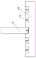
FIG. 1 is a front view of the present invention;
FIG. 2 is a left side view of the present invention;
FIG. 3 is an enlarged view of portion A of FIG. 2;
fig. 4 is a top view of the present invention;
FIG. 5 is a schematic structural view of the present invention in use;
FIG. 6 is a schematic structural diagram of the sheath tube;
in the figure: 1. a pin shaft; 2. a blade; 3. fixing the stud; 4. a pi-shaped plate; 5. a screw; 6. a threading plate; 7. a circular arc slide hole; 8. a groove; 9. threading holes; 10. a nut; 11. a thread groove; 12. a cable insulating sheath; 13. a cable core; 14. sheathing a pipe; 15. and (4) opening.
The specific implementation mode is as follows:
example 1:
a peeling device for a building electric cable comprises a threading plate 6 and a pi-shaped plate 4, wherein the right end of the pi-shaped plate is inserted into a groove 8 on the threading plate and is fixed by a screw 5, the bottom surface of the groove of the threading plate is provided with a thread groove 11, the screw penetrates through a threaded hole on a horizontal plate of the pi-shaped plate and is screwed into the thread groove, so that the pi-shaped plate and the threading plate are fixed, a blade 2 is arranged between two vertical plates of the pi-shaped plate, a pin shaft 1 is arranged in a round hole at the left end of the blade in a penetrating manner, a fixing stud 3 is arranged in the round hole in the middle of the blade in a penetrating manner and is fixedly adhered with the fixing stud, the fixing stud penetrates through an arc pi sliding hole 7 on the vertical plate at the corresponding side and is in threaded connection with a nut 10, a group of holes 9 are arranged in the length direction of the threading plate, and a protective sleeve 14 which is horizontally arranged is adhered at each threading hole, the protective sleeve consists of two semicircular plates 15 which are bilaterally symmetrical, a gap is formed between the two semicircular plates, and the distance of the gap is greater than the thickness of the blade.
Example 2:
according to embodiment 1, the grooves are formed in the upper side and the lower side of the threading plate, and the threading holes are located between the two grooves which correspond to each other up and down.
When the cable sheath peeling device is used, a part of the sheath of the cable is peeled off, as shown in fig. 5, the threading plate is provided with a plurality of threading holes, each threading hole corresponds to one size of the cable, and the corresponding cable from left to right of the threading hole is 2.5mm as shown in fig. 22、4mm2、6mm2、8mm2、10mm2Thus, the corresponding threading hole is selected according to the size of the cable to be stripped, after the threading hole is selected, the screw of the two Pi-shaped plates is unscrewed, the two Pi-shaped plates are inserted into the grooves at the upper end and the lower end of the corresponding threading hole and fixed, then the right end of the cable passes through the sheath tube and the threading hole, the nut is unscrewed, the blades at the upper end and the lower end are rotated, the gap distance between the two semicircular plates of the sheath tube is larger than the thickness of the blades, the position of the gap is positioned under the upper side blades and is positioned over the lower side blades or the blades can pass through the gap, the blades are rotated until the blades are contacted with the cable core 13 after the right end of the cable is stripped, the upper blades and the lower blades rotate to the position, then the nut is fixed, the sheath tube can ensure that the blades can always cut the insulating sheath 12 of the cable when the cable is pulled, as shown in figure 5, when the, the blade cuts the insulating crust of cable always, and upper and lower both ends are cut simultaneously, cut apart into two parts about the crust, then along with the pulling of cable, the insulating crust of cable peels off under the stopping of protecting pipe.
Claims (2)
1. The utility model provides a building electric cable peeling device which characterized by: this building electric cable device of skinning includes threading board and pi shaped plate, the right-hand member of pi shaped plate insert the threading board on the recess in and through the fix with screw, two vertical boards of pi shaped plate between set up the blade, the round hole of blade left end in wear to establish the round pin axle, the round hole at blade middle part in wear to establish fixed double-screw bolt and with fixed double-screw bolt bond fixedly, fixed double-screw bolt pass behind the circular arc slide opening on the vertical board of the pi shaped plate of corresponding side with nut threaded connection, the length direction of threading board on seted up a set of through wires hole, each threading hole department all bond the protective sheath that has a level to set up, protective sheath constitute by two semicircle boards of bilateral symmetry.
2. The building electric cable peeling device as claimed in claim 1, wherein: the upper side and the lower side of the threading plate are provided with the grooves, and the threading holes are positioned between the two grooves which correspond up and down.
Priority Applications (1)
| Application Number | Priority Date | Filing Date | Title |
|---|---|---|---|
| CN202020230520.2U CN211239128U (en) | 2020-03-01 | 2020-03-01 | Electric cable peeling device for building |
Applications Claiming Priority (1)
| Application Number | Priority Date | Filing Date | Title |
|---|---|---|---|
| CN202020230520.2U CN211239128U (en) | 2020-03-01 | 2020-03-01 | Electric cable peeling device for building |
Publications (1)
| Publication Number | Publication Date |
|---|---|
| CN211239128U true CN211239128U (en) | 2020-08-11 |
Family
ID=71923513
Family Applications (1)
| Application Number | Title | Priority Date | Filing Date |
|---|---|---|---|
| CN202020230520.2U Expired - Fee Related CN211239128U (en) | 2020-03-01 | 2020-03-01 | Electric cable peeling device for building |
Country Status (1)
| Country | Link |
|---|---|
| CN (1) | CN211239128U (en) |
-
2020
- 2020-03-01 CN CN202020230520.2U patent/CN211239128U/en not_active Expired - Fee Related
Similar Documents
| Publication | Publication Date | Title |
|---|---|---|
| CN101625914B (en) | Peeling device of insulated single wire | |
| CN211239128U (en) | Electric cable peeling device for building | |
| CN107947036B (en) | Single-core crosslinked polyethylene cable outer semiconductive shielding layer annular cutter | |
| CN108183431A (en) | A kind of rotation clamped-in style waste wire peeling wrap-up | |
| CN209088422U (en) | A kind of auxiliary tool of conducting wire skin stripping | |
| CN208316199U (en) | A kind of insulated overhead conductor wire stripper | |
| CN213989926U (en) | Equipment is peeld to communication cable | |
| KR101197744B1 (en) | The cable jacket stripper device | |
| CN206775016U (en) | A kind of cable insulation wrapper fixed-length cutting device | |
| CN201749746U (en) | Insulated single wire stripping tool | |
| CN109347008B (en) | Power cable stripping device | |
| CN202276057U (en) | Simple wire stripper | |
| CN203932644U (en) | A kind of steel reinforced aluminium conductor stripping silk device | |
| CN211789591U (en) | Lightning protection lightning arrester for metal pipeline joint | |
| CN201226423Y (en) | Apparatus for peeling cable oversheath | |
| CN107086504A (en) | A kind of cable peeling knife | |
| CN219268340U (en) | Cable stripping tool | |
| CN202978133U (en) | Device for stripping insulation sheaths of waste wires | |
| CN210156833U (en) | Adjustable cable stripping device for building electrical field | |
| CN206023136U (en) | A kind of bypass lead-up cable fixing device | |
| CN214590253U (en) | Peeling device for waste cables | |
| CN202678853U (en) | Cross-linked cable stripping cutter | |
| CN202797579U (en) | Rapid wiring device | |
| CN218677579U (en) | 400 volt combined type parallel groove clamp | |
| CN206195241U (en) | General wing section fixture with adjustable 500kV transmission line strain insulator tower tower head end |
Legal Events
| Date | Code | Title | Description |
|---|---|---|---|
| GR01 | Patent grant | ||
| GR01 | Patent grant | ||
| CF01 | Termination of patent right due to non-payment of annual fee | ||
| CF01 | Termination of patent right due to non-payment of annual fee |
Granted publication date: 20200811 Termination date: 20210301 |