CN211220288U - Ceramic tile edging dust collecting system - Google Patents
Ceramic tile edging dust collecting system Download PDFInfo
- Publication number
- CN211220288U CN211220288U CN201922310587.7U CN201922310587U CN211220288U CN 211220288 U CN211220288 U CN 211220288U CN 201922310587 U CN201922310587 U CN 201922310587U CN 211220288 U CN211220288 U CN 211220288U
- Authority
- CN
- China
- Prior art keywords
- water tank
- fixedly connected
- fan
- pipe
- intercommunication
- Prior art date
- Legal status (The legal status is an assumption and is not a legal conclusion. Google has not performed a legal analysis and makes no representation as to the accuracy of the status listed.)
- Active
Links
Images


Abstract
The utility model discloses a ceramic tile edging dust collecting system, comprising a water tank, the top intercommunication of water tank has the processing case, the first fan of left side fixedly connected with of processing case, the left side intercommunication of first fan air inlet has the suction hood, the inner chamber of processing case is from last to having set gradually filter screen, threaded rod, slide bar, outlet pipe and outlet duct down, the surperficial cover of threaded rod is equipped with the thread bush, the top fixedly connected with brush of thread bush. The utility model discloses a set up the water tank, handle case, first fan, air inlet cover, filter screen, threaded rod, slide bar, outlet pipe, outlet duct, thread bush, brush, sliding sleeve, shower nozzle, venthole, first motor, water pump, inlet tube, blast pipe, second fan, filter plate, second motor, rotary rod and puddler, solved the relatively poor problem of current ceramic tile edging dust collecting system practicality, this ceramic tile edging dust collecting system possesses the advantage that the practicality is high, is worth promoting.
Description
Technical Field
The utility model relates to a ceramic tile processing technology field specifically is a ceramic tile edging dust collection system.
Background
The ceramic tile is made of refractory metal oxide and semimetal oxide through the processes of grinding, mixing, pressing, glazing and sintering, and is acid-alkali-resistant porcelain or stone and the like, building or decoration materials are called as the ceramic tile, raw materials of the ceramic tile are mostly formed by mixing clay, quartz sand and the like, the ceramic tile, the polished tile, the spot tile, the crystal tile and the unglazed tile are printed according to the production process, the prior ceramic tile needs to be edged in the production and processing process, a large amount of dust is generated during edging of the ceramic tile, and the dust is directly scattered in the air and can generate adverse effects on the body of a worker, so that the cleaning of a filter screen and the discharge of the dust are inconvenient by using a common dust collecting device, the practicability of the dust collecting device is reduced, and the use is not facilitated.
SUMMERY OF THE UTILITY MODEL
An object of the utility model is to provide a ceramic tile edging dust collecting system possesses the high advantage of practicality, has solved the relatively poor problem of current ceramic tile edging dust collecting system practicality.
In order to achieve the above object, the utility model provides a following technical scheme: a ceramic tile edging dust collecting system comprises a water tank, wherein the top of the water tank is communicated with a processing box, the left side of the processing box is fixedly connected with a first fan, the left side of an air inlet of the first fan is communicated with an air inlet cover, an inner cavity of the processing box is sequentially provided with a filter screen, a threaded rod, a sliding rod, an outlet pipe and an outlet pipe from top to bottom, the surface of the threaded rod is sleeved with a threaded sleeve, the top of the threaded sleeve is fixedly connected with a hairbrush, the surface of the sliding rod is sleeved with a sliding sleeve, the top of the sliding sleeve is fixedly connected with the threaded sleeve, the bottom of the outlet pipe is communicated with a nozzle, the bottom of the outlet pipe is provided with an air outlet hole, the left end of the outlet pipe penetrates through the left side of the processing box, the right end of the outlet pipe penetrates through the right side of the processing box, the top on the right side, the bottom of first fan is passed through pipe and outlet duct intercommunication, the right side fixedly connected with water pump at water tank top, pipe and outlet pipe intercommunication are passed through at the top of water pump, the bottom intercommunication of water pump has the inlet tube, the bottom of inlet tube runs through to the inner chamber of water tank, the top intercommunication of handling the case has the blast pipe, the inner chamber of blast pipe is provided with the second fan, the inner chamber of water tank and the left side that is located the inlet tube are provided with the filter plate, the left side fixedly connected with second motor of water tank, the right side fixedly connected with rotary rod of second motor output, the right-hand member of rotary rod run through to the inner chamber of water tank and with filter plate swing joint, the equal fixedly connected with puddler in right side of rotary rod top.
Preferably, the bottom fixedly connected with of water tank removes the wheel, the quantity that removes the wheel is four, and evenly distributed in the four corners of water tank bottom, the top and the filter screen contact of brush.
Preferably, the bottom intercommunication of water tank has the blow off pipe, and the surface cover of blow off pipe is equipped with the valve, handle the equal fixedly connected with guide plate in both sides of incasement chamber bottom and the left side of water tank inner chamber bottom, and the guide plate is triangle-shaped.
Preferably, the surface of filter screen and the inner wall fixed connection who handles the case, the surface of threaded rod and the junction of handling the case are through first bearing swing joint, the both ends of slide bar all with the inner wall fixed connection who handles the case, the surface of rotary rod all passes through second bearing swing joint with the junction of water tank and filter plate.
Preferably, both sides of the second fan are fixedly connected with a support, and one side of the support, far away from the second fan, is fixedly connected with the inner wall of the exhaust pipe.
Compared with the prior art, the beneficial effects of the utility model are as follows:
1. the utility model discloses a set up the water tank, handle case, first fan, air inlet cover, filter screen, threaded rod, slide bar, outlet pipe, outlet duct, thread bush, brush, sliding sleeve, shower nozzle, venthole, first motor, water pump, inlet tube, blast pipe, second fan, filter plate, second motor, rotary rod and puddler, solved the relatively poor problem of current ceramic tile edging dust collecting system practicality, this ceramic tile edging dust collecting system possesses the advantage that the practicality is high, is worth promoting.
2. The utility model discloses a set up the cover that admits air, can increase the scope of admitting air, through setting up filter screen and filter plate, can play filterable effect, through setting up the brush, can be used for clearing up the filter screen, through setting up slide bar and sliding sleeve, can restrict the removal scope of thread bush, through setting up the second motor, can accelerate gas flow, through setting up the puddler, can make the dust fully contact with water, make it mix in aqueous, through setting up the removal wheel, the removal of the whole device of can being convenient for, through setting up the blow off pipe, can play the effect of blowdown, through setting up the guide plate, can play the effect of water conservancy diversion.
Drawings
FIG. 1 is a schematic structural view of the present invention;
FIG. 2 is a front view of the structure of the present invention;
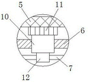
fig. 3 is a partially enlarged view of a in fig. 1 according to the present invention.
In the figure: 1. a water tank; 2. a treatment tank; 3. a first fan; 4. an air intake hood; 5. filtering with a screen; 6. a threaded rod; 7. a slide bar; 8. a water outlet pipe; 9. an air outlet pipe; 10. a threaded sleeve; 11. a brush; 12. a sliding sleeve; 13. a spray head; 14. an air outlet; 15. a first motor; 16. a water pump; 17. a water inlet pipe; 18. an exhaust pipe; 19. a second fan; 20. filtering the plate; 21. a second motor; 22. rotating the rod; 23. a stirring rod; 24. the wheel is moved.
Detailed Description
The technical solutions in the embodiments of the present invention will be described clearly and completely with reference to the accompanying drawings in the embodiments of the present invention, and it is obvious that the described embodiments are only some embodiments of the present invention, not all embodiments. Based on the embodiments in the present invention, all other embodiments obtained by a person skilled in the art without creative work belong to the protection scope of the present invention.
In the description of the present invention, it should be noted that the terms "upper", "lower", "inner", "outer", "front end", "rear end", "both ends", "one end", "the other end", and the like indicate orientations or positional relationships based on the orientations or positional relationships shown in the drawings, and are only for convenience of description and simplification of description, but do not indicate or imply that the device or element to be referred must have a specific orientation, be constructed in a specific orientation, and be operated, and thus, should not be construed as limiting the present invention. Furthermore, the terms "first" and "second" are used for descriptive purposes only and are not to be construed as indicating or implying relative importance.
In the description of the present invention, it is to be noted that, unless otherwise explicitly specified or limited, the terms "mounted", "provided", "connected", and the like are to be construed broadly, such as "connected", which may be fixedly connected, detachably connected, or integrally connected; can be mechanically or electrically connected; they may be connected directly or indirectly through intervening media, or they may be interconnected between two elements. The specific meaning of the above terms in the present invention can be understood in specific cases to those skilled in the art.
The utility model discloses a water tank 1, handle case 2, first fan 3, the inlet hood 4, filter screen 5, threaded rod 6, slide bar 7, outlet pipe 8, outlet duct 9, thread bush 10, brush 11, sliding sleeve 12, shower nozzle 13, venthole 14, first motor 15, water pump 16, inlet tube 17, blast pipe 18, second fan 19, filter plate 20, second motor 21, rotary rod 22 and puddler 23 part are the general standard or the part that technical staff in the field knows, its structure and principle all are that this technical staff all can learn through the technical manual or learn through conventional experimental approach.
Referring to fig. 1-3, a tile edging dust collection system comprises a water tank 1, the top of the water tank 1 is communicated with a processing box 2, the left side of the processing box 2 is fixedly connected with a first fan 3, the left side of an air inlet of the first fan 3 is communicated with an air inlet cover 4, an inner cavity of the processing box 2 is sequentially provided with a filter screen 5, a threaded rod 6, a sliding rod 7, an outlet pipe 8 and an outlet pipe 9 from top to bottom, the surface of the threaded rod 6 is sleeved with a threaded sleeve 10, the top of the threaded sleeve 10 is fixedly connected with a brush 11, the surface of the sliding rod 7 is sleeved with a sliding sleeve 12, the top of the sliding sleeve 12 is fixedly connected with the threaded sleeve 10, the bottom of the outlet pipe 8 is communicated with a spray head 13, the bottom of the outlet pipe 9 is provided with an air outlet hole 14, the left end of the outlet pipe 9 penetrates to the left side of the processing, the right end of the threaded rod 6 penetrates through the treatment tank 2 and is fixedly connected with the left side of the output end of the first motor 15, the bottom of the first fan 3 is communicated with the air outlet pipe 9 through a guide pipe, the right side of the top of the water tank 1 is fixedly connected with a water pump 16, the top of the water pump 16 is communicated with the water outlet pipe 8 through a guide pipe, the bottom of the water pump 16 is communicated with a water inlet pipe 17, the bottom of the water inlet pipe 17 penetrates through the inner cavity of the water tank 1, the top of the treatment tank 2 is communicated with an exhaust pipe 18, the inner cavity of the exhaust pipe 18 is provided with a second fan 19, the inner cavity of the water tank 1 and the left side of the water inlet pipe 17 are provided with a filter plate 20, the left side of the water tank 1 is fixedly connected with a second motor 21, the right side of the output end of the second motor 21, the bottom of the water tank 1 is fixedly connected with four moving wheels 24, the moving wheels 24 are uniformly distributed at four corners of the bottom of the water tank 1, the top of the hairbrush 11 is contacted with the filter screen 5, the bottom of the water tank 1 is communicated with a discharge pipe, the surface of the discharge pipe is sleeved with a valve, two sides of the bottom of the inner cavity of the treatment box 2 and the left side of the bottom of the inner cavity of the water tank 1 are fixedly connected with guide plates, the guide plates are triangular, the surface of the filter screen 5 is fixedly connected with the inner wall of the treatment box 2, the joint of the surface of the threaded rod 6 and the treatment box 2 is movably connected through a first bearing, two ends of the sliding rod 7 are fixedly connected with the inner wall of the treatment box 2, the joint of the surface of the rotating rod 22 and the water tank 1 and the filter plate 20 is movably connected through a second bearing, two sides of the second fan 19 are fixedly connected with, through setting up the inlet hood 4, can increase the scope of admitting air, through setting up filter screen 5 and filter plate 20, can play filterable effect, through setting up brush 11, can be used for clearing up filter screen 5, through setting up slide bar 7 and sliding sleeve 12, can restrict the range of movement of thread bush 10, through setting up second motor 21, can accelerate the gas flow, through setting up puddler 23, can make the dust fully contact with water, make it mix in aqueous, through setting up removal wheel 24, can facilitate the removal of whole device, through setting up the blow off pipe, can play the effect of blowdown, through setting up the guide plate, can play the effect of water conservancy diversion, through setting up water tank 1, handle case 2, first fan 3, inlet hood 4, filter screen 5, threaded rod 6, slide bar 7, outlet pipe 8, outlet duct 9, thread bush 10, brush 11, sliding sleeve 12, shower nozzle 13, venthole 14, First motor 15, water pump 16, inlet tube 17, blast pipe 18, second fan 19, filter plate 20, second motor 21, rotary rod 22 and puddler 23 have solved the relatively poor problem of current ceramic tile edging dust collecting system practicality, and this ceramic tile edging dust collecting system possesses the advantage that the practicality is high, is worth promoting.
When the water tank cleaning device is used, the first fan 3, the second fan 19 and the water pump 16 are started, the first fan 3 sucks dust generated by edging through the matching of the air inlet cover 4, gas with dust enters the air outlet pipe 9 and then is discharged from the air outlet hole 14, the water pump 16 pumps water in the water tank 1 through the matching of the water inlet pipe 17 and the water outlet pipe 8 and downwards sprays the water through the spray head 13, part of dust flows into the water tank 1 along with the water, the gas continuously moves upwards and is discharged from the air outlet pipe 18 after being filtered by the filter screen 5, the second fan 19 can accelerate the gas flow, the first motor 15 and the second motor 21 are started, the output end of the first motor 15 drives the threaded rod 6 to rotate, the threaded rod 6 can drive the threaded sleeve 10 to move, the threaded sleeve 10 moves to drive the brush 11 to clean the filter screen 5, the second motor 21 drives the rotary rod 22 to rotate, the rotary rod 22 drives the, the stirring rod 23 rotates to enable the dust to be fully contacted with water, so that the dust is mixed in the water, and the dust is conveniently discharged.
Although embodiments of the present invention have been shown and described, it will be appreciated by those skilled in the art that changes, modifications, substitutions and alterations can be made in these embodiments without departing from the principles and spirit of the invention, the scope of which is defined in the appended claims and their equivalents.
Claims (5)
1. The utility model provides a ceramic tile edging dust collection system, includes water tank (1), its characterized in that: the top intercommunication of water tank (1) has handles case (2), handle the first fan (3) of left side fixedly connected with of case (2), the left side intercommunication of first fan (3) air inlet has air inlet hood (4), the inner chamber of handling case (2) has set gradually filter screen (5), threaded rod (6), slide bar (7), outlet pipe (8) and outlet duct (9) from last to down, the surface cover of threaded rod (6) is equipped with thread bush (10), the top fixedly connected with brush (11) of thread bush (10), the surface cover of slide bar (7) is equipped with sliding sleeve (12), the top and the thread bush (10) fixed connection of sliding sleeve (12), the bottom intercommunication of outlet duct (8) has shower nozzle (13), venthole (14) have been seted up to the bottom of outlet duct (9), the left end of outlet duct (9) runs through to the left side of handling case (2), the right-hand member of outlet pipe (8) runs through to the right side of handling case (2), handle the top fixedly connected with first motor (15) on case (2) right side, the right-hand member of threaded rod (6) runs through handle case (2) and with the left side fixed connection of first motor (15) output, the bottom of first fan (3) is passed through pipe and outlet duct (9) intercommunication, the right side fixedly connected with water pump (16) at water tank (1) top, the top of water pump (16) is passed through pipe and outlet pipe (8) intercommunication, the bottom intercommunication of water pump (16) has inlet tube (17), the bottom of inlet tube (17) runs through to the inner chamber of water tank (1), the top intercommunication of handling case (2) has blast pipe (18), the inner chamber of blast pipe (18) is provided with second fan (19), the inner chamber of water tank (1) and the left side that is located inlet tube (17) are provided with filter plate (20), the left side fixedly connected with second motor (21) of water tank (1), the right side fixedly connected with rotary rod (22) of second motor (21) output, the right-hand member of rotary rod (22) run through to the inner chamber of water tank (1) and with filter plate (20) swing joint, the equal fixedly connected with puddler (23) in right side of rotary rod (22) top and bottom.
2. A tile edging dust collection system according to claim 1, wherein: the bottom fixedly connected with of water tank (1) removes wheel (24), the quantity that removes wheel (24) is four, and evenly distributed in the four corners of water tank (1) bottom, the top and the filter screen (5) contact of brush (11).
3. A tile edging dust collection system according to claim 1, wherein: the bottom intercommunication of water tank (1) has the blow off pipe, and the surface cover of blow off pipe is equipped with the valve, handle the equal fixedly connected with guide plate in both sides of case (2) inner chamber bottom and the left side of water tank (1) inner chamber bottom, and the guide plate is triangle-shaped.
4. A tile edging dust collection system according to claim 1, wherein: the surface of filter screen (5) and the inner wall fixed connection who handles case (2), the surface of threaded rod (6) and the junction of handling case (2) are through first bearing swing joint, the both ends of slide bar (7) all with the inner wall fixed connection who handles case (2), the surface of rotary rod (22) all passes through second bearing swing joint with the junction of water tank (1) and filter plate (20).
5. A tile edging dust collection system according to claim 1, wherein: the two sides of the second fan (19) are fixedly connected with supports, and one side, away from the second fan (19), of each support is fixedly connected with the inner wall of the exhaust pipe (18).
Priority Applications (1)
| Application Number | Priority Date | Filing Date | Title |
|---|---|---|---|
| CN201922310587.7U CN211220288U (en) | 2019-12-20 | 2019-12-20 | Ceramic tile edging dust collecting system |
Applications Claiming Priority (1)
| Application Number | Priority Date | Filing Date | Title |
|---|---|---|---|
| CN201922310587.7U CN211220288U (en) | 2019-12-20 | 2019-12-20 | Ceramic tile edging dust collecting system |
Publications (1)
| Publication Number | Publication Date |
|---|---|
| CN211220288U true CN211220288U (en) | 2020-08-11 |
Family
ID=71935550
Family Applications (1)
| Application Number | Title | Priority Date | Filing Date |
|---|---|---|---|
| CN201922310587.7U Active CN211220288U (en) | 2019-12-20 | 2019-12-20 | Ceramic tile edging dust collecting system |
Country Status (1)
| Country | Link |
|---|---|
| CN (1) | CN211220288U (en) |
Cited By (2)
| Publication number | Priority date | Publication date | Assignee | Title |
|---|---|---|---|---|
| CN112247765A (en) * | 2020-10-21 | 2021-01-22 | 浙江贝斯特软化板有限公司 | Environment-friendly grinding device that water paint pencil processing was used |
| CN112571255A (en) * | 2020-12-09 | 2021-03-30 | 南京思达捷信息科技有限公司 | A polishing equipment for hardware equipment processing |
-
2019
- 2019-12-20 CN CN201922310587.7U patent/CN211220288U/en active Active
Cited By (2)
| Publication number | Priority date | Publication date | Assignee | Title |
|---|---|---|---|---|
| CN112247765A (en) * | 2020-10-21 | 2021-01-22 | 浙江贝斯特软化板有限公司 | Environment-friendly grinding device that water paint pencil processing was used |
| CN112571255A (en) * | 2020-12-09 | 2021-03-30 | 南京思达捷信息科技有限公司 | A polishing equipment for hardware equipment processing |
Similar Documents
| Publication | Publication Date | Title |
|---|---|---|
| CN211220288U (en) | Ceramic tile edging dust collecting system | |
| CN211159106U (en) | Special dust collecting equipment of concrete preparation of high-efficient environmental protection | |
| CN210757203U (en) | Noise reduction finishing grinding chamber | |
| CN208231523U (en) | A kind of ceramic making hand-held burnishing device | |
| CN211098216U (en) | A dust collector for carborundum production facility | |
| CN218638164U (en) | Automatic dust remover in workshop for producing chrome-zirconium corundum | |
| CN217512408U (en) | Surface cleaning device is used in ceramic tile production | |
| CN210409989U (en) | Special dust collecting equipment of ceramic manufacture | |
| CN211936174U (en) | Dust device for municipal works | |
| CN211194428U (en) | Concrete mixing device for highway construction | |
| CN212553118U (en) | Clean efficient pottery apparatus for producing that polishes | |
| CN220424919U (en) | Dust collector is used in concrete production | |
| CN217226032U (en) | Cleaning device for processing decorative bricks | |
| CN219002482U (en) | Dust removal mechanism of concrete mixing plant | |
| CN220656942U (en) | Concrete dust collector | |
| CN220328274U (en) | Dust collector for quartz sand production | |
| CN210335296U (en) | Milling machine cleaning device of plastic part production usefulness | |
| CN216329036U (en) | Water spray humidifying device before ceramic tile cloth glaze | |
| CN217857540U (en) | Ceramic tile surface dust removal device | |
| CN213470745U (en) | Ceramic tile production burnishing device | |
| CN212613561U (en) | Wall cleaning device for fixing wall tiles | |
| CN210909570U (en) | Line platform of polishing of door plant preparation usefulness | |
| CN211103102U (en) | Marble buffing machine with water smoke dust device | |
| CN213665094U (en) | Floor cleaning machine with good stability | |
| CN220162184U (en) | Dust collector is used in ceramic manufacture polishing |
Legal Events
| Date | Code | Title | Description |
|---|---|---|---|
| GR01 | Patent grant | ||
| GR01 | Patent grant |