CN211214280U - Intelligent massage equipment and massage mechanism thereof - Google Patents
Intelligent massage equipment and massage mechanism thereof Download PDFInfo
- Publication number
- CN211214280U CN211214280U CN201921843540.0U CN201921843540U CN211214280U CN 211214280 U CN211214280 U CN 211214280U CN 201921843540 U CN201921843540 U CN 201921843540U CN 211214280 U CN211214280 U CN 211214280U
- Authority
- CN
- China
- Prior art keywords
- massage
- swing arm
- head
- air bag
- massage mechanism
- Prior art date
- Legal status (The legal status is an assumption and is not a legal conclusion. Google has not performed a legal analysis and makes no representation as to the accuracy of the status listed.)
- Active
Links
Images


Landscapes
- Massaging Devices (AREA)
Abstract
The utility model discloses an intelligent massage device and a massage mechanism thereof, wherein the massage mechanism comprises a massage head, a lifting mechanism and a translation mechanism; the massage head comprises a massage ball, a swing arm and a swing arm driving device, wherein the swing arm comprises a first swing arm section and a second swing arm section which are distributed in an L shape, the massage ball is arranged at the free end of the first swing arm section, and the swing arm driving device is connected with the second swing arm section and is used for controlling the second swing arm section to rotate; the lifting mechanism is used for controlling the massage head to move along the lifting direction, and the lifting direction is parallel to the rotating shaft of the second section of the swing arm; the translation mechanism is used for controlling the massage head to move linearly in a plane vertical to the lifting direction. The application provides a massage mechanism is in using, and when the user size changed, it can be according to the position of actual demand adjustment massage head to the travelling comfort and the precision of massage have been improved.
Description
Technical Field
The utility model relates to a massage equipment technical field, more specifically say, relate to a massage mechanism. Furthermore, the utility model discloses still relate to an intelligent massage equipment including above-mentioned massage mechanism.
Background
With the acceleration of modern life rhythm and the increase of working intensity, the incidence rate of neck and lumbar diseases as common diseases is on the rise, and people usually relieve the neck and lumbar diseases by massage.
If the massage is carried out manually, a masseur can accurately determine the acupuncture points of the user according to the actual physical condition of the user, and the massage is carried out appropriately. However, the massage heads equipped in the current massage equipment on the market are all fixed, the motion track of the massage balls is fixed and unchanged, when the body type of the user changes, the position of the massage heads cannot be changed, so that the current massage equipment cannot be adjusted adaptively according to the body type change of the user, the acupuncture points cannot be identified accurately, the effect of massage therapist manipulation treatment is achieved, the massage equipment can only achieve ordinary relaxation massage, and the effects of relaxing muscles and slightly relieving fatigue are achieved.
In summary, how to adjust the massage position according to the user requirement so as to improve the comfort and accuracy of the massage is a problem to be urgently solved by those skilled in the art.
SUMMERY OF THE UTILITY MODEL
In view of this, the utility model aims at providing a massage mechanism, it can be according to user's demand adjustment massage position, has improved the travelling comfort and the precision of massage. Another object of the utility model is to provide an intelligent massage equipment including above-mentioned massage mechanism.
In order to achieve the above object, the present invention provides the following technical solutions:
a massage mechanism comprising:
the massage head comprises a massage ball, a swing arm and a swing arm driving device, wherein the swing arm comprises a first swing arm section and a second swing arm section which are distributed in an L shape, the massage ball is arranged at the free end of the first swing arm section, and the swing arm driving device is connected with the second swing arm section and is used for controlling the second swing arm section to rotate;
the lifting mechanism is used for controlling the massage head to move along the lifting direction, and the lifting direction is parallel to the rotating shaft of the second section of the swing arm;
and the translation mechanism is used for controlling the massage head to linearly move in a plane vertical to the lifting direction.
Preferably, the swing arm is tubulose, the massage head still including locating the inside L shape of swing arm steel wire flexible axle, the one end of steel wire flexible axle links to each other with the output shaft of massage ball motor, another pot head of steel wire flexible axle be equipped with massage ball fixed connection, and can the inside free rotation's of swing arm connector.
Preferably, the swing arm driving device comprises a swing arm motor, a driving swing arm gear fixedly sleeved on an output shaft of the swing arm motor, and a driven swing arm gear meshed with the driving swing arm gear and sleeved on the periphery of the second section of the swing arm.
Preferably, the fixed end of the lifting mechanism is connected with the movable end of the translation mechanism, and the movable end of the lifting mechanism is connected with the massage head.
Preferably, the translation mechanism comprises a bottom plate, a linear guide rail arranged on the bottom plate, and a sliding plate which is in sliding fit with the linear guide rail and is connected with the fixed end of the lifting mechanism, the bottom plate is provided with a driving synchronous pulley, a driven synchronous pulley and a synchronous belt fixedly connected with the sliding plate, and a driving shaft of the translation motor is connected with the driving synchronous pulley to control the driving synchronous pulley to rotate.
Preferably, elevating system include ball, with ball screw thread fit's lifting nut, be used for the drive the rotatory lift actuating mechanism of ball, top with massage head link to each other and with the fixed sliding sleeve of lifting nut, with bottom plate fixed connection's fixing base, the fixing base is equipped with the restriction the spacing portion of sliding sleeve circumferential direction rotation.
The utility model provides an intelligence massage equipment, includes the front supporting pad that is used for supporting user's health, the back of supporting pad is equipped with above-mentioned arbitrary massage mechanism.
Preferably, the support pad comprises an air bag bed core with the back facing the massage mechanism and provided with a plurality of air bag groups, each air bag group comprises a plurality of communicated sub air bags, the sub air bags of all the air bag groups are distributed in a row, and the plurality of sub air bags in the air bag group corresponding to the position of the massage mechanism are sequentially distributed along the translation direction of the massage mechanism;
further comprising:
the control system is electrically connected with the airflow control device, the translation mechanism of the massage mechanism and the lifting mechanism of the massage mechanism respectively; the control system is used for controlling the translation mechanism and the lifting mechanism to act so as to enable the massage head of the massage mechanism to move according to a preset path and sending a pressure regulating instruction to the airflow control device when receiving a massage instruction;
with a plurality of that gasbag group one-to-one is connected air current controlling means, air current controlling means is used for receiving during the pressure regulating instruction, reduce with massage mechanism position corresponds the atmospheric pressure of gasbag group.
Preferably, the support pad further comprises a cushion layer mattress core which is attached to the front surface of the airbag mattress core and used for supporting the body of a user, and the cushion layer mattress core is provided with an avoiding notch corresponding to the position of the massage mechanism and used for allowing the massage mechanism to move.
Preferably, the massage mechanism comprises any one or combination of any more of a head massage mechanism, a neck and shoulder massage mechanism and a back massage mechanism;
when the massage mechanism comprises the head massage mechanism, the air bag group comprises a head air bag for supporting the head, the head massage mechanism is arranged on the side part of the head air bag, and the translation direction of the head massage mechanism is parallel to the Y axis; the air flow control device connected with the head air bag is used for reducing the air pressure of the head air bag when receiving a head pressure regulating instruction;
when the massage mechanism comprises the neck and shoulder massage mechanism, the air bag group comprises a neck air bag for supporting the neck, and the translation direction of the neck and shoulder massage mechanism is parallel to the X axis; the air flow control device is connected with the neck air bag and is used for reducing the air pressure of the neck air bag when receiving a neck pressure regulating instruction; the X axis and the Y axis are vertically distributed, and the plane where the X axis and the Y axis are located is vertical to the lifting direction;
when the massage mechanism comprises the back massage mechanism, the air bag group comprises a spine central air bag for supporting a spine, and a spine side air bag which is positioned at the side part of the spine central air bag and corresponds to the position of the back massage mechanism, and the translation direction of the back massage mechanism is parallel to the Y axis; and the airflow control device connected with the spine side air bag is used for acting when receiving a back pressure regulating instruction, so that the air pressure of the spine side air bag is smaller than that of the spine central air bag.
The massage mechanism provided by the utility model comprises a massage head, a lifting mechanism and a translation mechanism; the massage head comprises a massage ball, an L-shaped swing arm and a swing arm driving device, wherein the free end of the first section of the swing arm is connected with the massage ball, and the second section of the swing arm rotates under the control of the swing arm driving device; the lifting mechanism and the translation mechanism are respectively used for controlling the massage head to move along a lifting direction and a preset straight line, the lifting direction is parallel to the rotating shaft of the second section of the swing arm, and the plane of the preset straight line is vertical to the lifting direction.
In the working process, if the lifting direction is the z-axis direction, the direction of the preset straight line is the x-axis direction, and the plane of the preset straight line is the xy plane, the swing arm driving device can control the massage head to rotate around the z-axis, the lifting mechanism controls the massage head to translate along the z-axis, the translation mechanism controls the massage head to translate along the x-axis, and the swing arm driving device and the translation mechanism are combined to realize the movement of the massage head along the y-axis. Namely, under the condition that multiple movements are combined with each other, the massage heads can move in the xyz axis direction, so that when the position needing massage changes, the massage mechanism can adjust the positions of the massage heads according to actual requirements, and the effect of matching the actual requirements of users and improving the massage effect is achieved.
The application also provides an intelligent massage device with the beneficial effects.
Drawings
In order to more clearly illustrate the embodiments of the present invention or the technical solutions in the prior art, the drawings required to be used in the description of the embodiments or the prior art will be briefly described below, it is obvious that the drawings in the following description are only embodiments of the present invention, and for those skilled in the art, other drawings can be obtained according to the provided drawings without creative efforts.
FIG. 1 is a first perspective view of a massage mechanism;
FIG. 2 is a second perspective view of the massage mechanism;
FIG. 3 is a cross-sectional view of the massage mechanism;
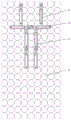
fig. 4 is a top view of the intelligent massage device;
fig. 5 is a side view of the intelligent massage device;
fig. 6 is a schematic structural view of the massage mattress body.
The reference numerals in figures 1 to 6 are:
a bottom plate 1, a belt wheel fixing shaft 2, a driven synchronous belt wheel 3, a second deep groove ball bearing 4, a proximity switch 5, a sensor bracket 6, a synchronous belt 7, a linear guide rail 8, a driving gear 9, a lifting motor 10, an idler wheel 11, a screw bearing 12, a swing arm motor 13, a motor fixing plate 14, a motor shield 15, a driving swing arm gear 16, a sensing plate 17, a driven swing arm gear 18, a bearing cover 19, a connecting plate 20, a massage ball motor 21, a swing arm 22, a steel wire flexible shaft 23, a connecting head 24, a first deep groove ball bearing 25, a massage ball 26, a sliding sleeve 27, a steel sleeve 28, a steel ball 29, a ball screw 30, a fixing seat 31, a lifting nut 32, a third deep groove ball bearing 33, a sliding plate 34, a lifting gear 35, a driving synchronous belt wheel 36, a motor fixing seat 37, a transverse moving motor 38, a stabilizing frame 39, a balance frame 40, a deformation air, A bed cover 44, a back massage mechanism 45, a neck and shoulder massage mechanism 46 and a head massage mechanism 47.
Detailed Description
The technical solutions in the embodiments of the present invention will be described clearly and completely with reference to the accompanying drawings in the embodiments of the present invention, and it is obvious that the described embodiments are only some embodiments of the present invention, not all embodiments. Based on the embodiments in the present invention, all other embodiments obtained by a person skilled in the art without creative work belong to the protection scope of the present invention.
Referring to fig. 1 to 6, fig. 1 is a schematic structural view of a first view angle of a massage mechanism; FIG. 2 is a second perspective view of the massage mechanism; FIG. 3 is a cross-sectional view of the massage mechanism; fig. 4 is a top view of the intelligent massage device; fig. 5 is a side view of the intelligent massage device; fig. 6 is a schematic structural view of the massage mattress body. In order to conveniently display the position relation of various massage mechanisms, the massage mechanism is displayed above the air bag bed core in fig. 4, and in actual use, the massage mechanism should be positioned at the back of the air bag bed core, namely, in a top view, the massage mechanism should be shielded by the air bag bed core.
The application provides a massage mechanism, which comprises a massage head, a lifting mechanism and a translation mechanism. Wherein, the massage head includes massage ball 26, swing arm 22, swing arm drive arrangement, and swing arm 22 is including being the first section of swing arm and the swing arm second section that L shape distributes, and massage ball 26 locates the free end of first section of swing arm, and swing arm drive arrangement links to each other with swing arm second section, is used for controlling the swing arm second section rotatory. The lifting mechanism is used for controlling the massage head to move along the lifting direction, and the lifting direction is parallel to the rotating shaft of the second section of the swing arm. The translation mechanism is used for controlling the massage head to move linearly in a plane vertical to the lifting direction.
Specifically, the massage ball 26 plays a role of massage, and in order to ensure a massage effect, it usually has a convex massage structure, for example, it has a first massage protrusion protruding along the axial direction of the first segment of the swing arm, or has a second massage protrusion protruding toward the direction away from the axis of the first segment of the swing arm, and preferably, the first massage protrusion and the second massage protrusion are both provided on the same massage ball 26.
The swing arm driving device, the lifting mechanism and the translation mechanism are three driving mechanisms and are used for controlling the massage balls 26 to move along different directions. In the working process, the swing arm driving device controls the second section of the swing arm to rotate, and then the massage ball 26 is driven to rotate around the second section of the swing arm. The elevating mechanism controls the massage balls 26 to move linearly in the elevating direction, and the translation mechanism controls the massage balls 26 to move linearly in the translation direction.
In the working process, if the lifting direction is the z-axis direction, the direction of the preset straight line is the x-axis direction, and the plane of the preset straight line is the xy plane, the swing arm driving device can control the massage head to rotate around the z-axis, the lifting mechanism controls the massage head to translate along the z-axis, the translation mechanism controls the massage head to translate along the x-axis, and the swing arm driving device and the translation mechanism are combined to realize the movement of the massage head along the y-axis. That is, in the case where a plurality of motions are combined with each other, the massage head can realize simultaneous motions in the xyz-axis direction.
It should be noted that, because there are many possibilities for the placement direction of the massage mechanism in the actual application process, the x-axis, the y-axis, and the z-axis in the present application only refer to relative position relationships, and the actual directions of the three in the application process need to be determined according to actual situations.
The application provides a massage mechanism can adjust the position of massage head according to actual demand, matches user's actual demand to the travelling comfort and the precision of massage have been improved.
Further, in an embodiment provided by the present application, the swing arm 22 is tubular, the massage head further includes an L-shaped flexible steel wire shaft 23 disposed inside the swing arm 22, one end of the flexible steel wire shaft 23 is connected to an output shaft of the massage ball motor 21, and the other end of the flexible steel wire shaft 23 is sleeved with a connector 24 which is fixedly connected to the massage ball 26 and can freely rotate inside the swing arm 22. Specifically, the massage ball motor 21 drives the flexible steel wire shaft 23 to rotate, the flexible steel wire shaft 23 is limited by the swing arm 22, and can rotate around the axis of the massage ball 26 on the basis of integrally keeping the L-shaped distribution, so that the second massage structure of the massage head can rotate around the axis of the first section of the swing arm. In order to facilitate the rotation of the connection head 24, a first deep groove ball bearing 25 may be provided between the connection head 24 and the swing arm 22.
Optionally, in an embodiment of the swing arm driving apparatus provided in the present application, the swing arm driving apparatus includes a swing arm motor 13, a driving swing arm gear 16, and a driven swing arm gear 18. Wherein, the driving swing arm gear 16 is fixedly sleeved with the output shaft of the swing arm motor 13, the driven swing arm gear 18 is sleeved on the periphery of the second section of the swing arm, and meanwhile, the driving swing arm gear 16 is in meshed transmission with the driven swing arm gear 18 to realize the rotation of the second section of the swing arm. Alternatively, a sensing plate 17 may be provided to detect the rotation angle of the swing arm 22.
Optionally, in an embodiment provided by the present application, the fixed end of the lifting mechanism is connected to the movable end of the translation mechanism, and the movable end of the lifting mechanism is connected to the massage head. In the actual assembling process, the massage head can be provided with a support frame to realize the connection of all the parts, for example, the support frame can comprise a connecting plate 20, a motor shield 15, a motor fixing plate 14 and a bearing cover 19, and the movable end of the lifting mechanism is connected with the connecting plate 20 of the support frame, so that the massage head is indirectly driven to move integrally. The massage ball motor 21 and the swing arm motor 13 can be fixed on the motor fixing plate 14.
Optionally, in an embodiment of the translation mechanism provided by the present application, the translation mechanism includes a base plate 1, a linear guide 8, a sliding plate 34, a driving synchronous pulley 36, a driven synchronous pulley 3, a synchronous belt 7, and a traverse motor 38. The transverse moving motor 38 is fixed on the bottom plate 1 through a motor fixing seat 37, the driving synchronous pulley 36, the driven synchronous pulley 3 and the synchronous belt 7 form a belt transmission mechanism, the driving synchronous pulley 36 is connected with a driving shaft of the transverse moving motor 38 and rotates under the control of the driving synchronous pulley 36, the driven synchronous pulley 3 is connected with the bottom plate 1 through a pulley fixing shaft 2 and keeps rotating smoothly through a second deep groove ball bearing 4, the synchronous belt 7 is fixedly connected with the sliding plate 34, the linear guide rail 8 is arranged on the bottom plate 1, the sliding plate 34 is in sliding fit with the linear guide rail 8, and the sliding plate 34 is connected with the fixing end of the lifting mechanism. Therefore, when the traverse motor 38 is started, the slide plate 34 moves the entire lifting mechanism on the linear guide 8.
Optionally, the translation mechanism may also be provided with a proximity switch 5 for detecting the position of the slide 34, the proximity switch 5 being fixed to the base plate 1 by means of the sensor bracket 6.
Optionally, in an embodiment of the lifting mechanism provided in the present application, the lifting mechanism includes a ball screw 30, a lifting nut 32, a lifting driving mechanism, a sliding sleeve 27, and a fixing seat 31. Wherein, ball 30 and lift nut 32 screw-thread fit, lift actuating mechanism links to each other with ball 30, is used for driving ball 30 rotatory, and sliding sleeve 27 and lift nut 32 keep fixed, and the top of sliding sleeve 27 passes through connecting plate 20 and links to each other with the massage head, and the lower extreme and the bottom plate 1 fixed connection of fixing base 31. The fixing seat 31 is provided with a limiting portion for limiting circumferential rotation of the sliding sleeve 27, the limiting portion can specifically comprise steel balls 29, the steel balls 29 are separated through a steel sleeve 28, at the moment, the sliding sleeve 27 is sleeved on the periphery of the ball screw 30, and the outer side wall of the sliding sleeve 27 needs to be provided with a sliding groove matched with the steel balls 29. The fixing seat 31 may be tubular and is sleeved on the periphery of the sliding sleeve 27.
Optionally, in an embodiment of the lifting driving mechanism provided by the present application, the lifting driving mechanism includes a lifting motor 10, a driving gear 9, and a lifting gear 35. Wherein, the driving gear 9 is fixedly connected with a driving shaft of the lifting motor 10 and rotates under the control of the lifting motor 10, the lifting gear 35 is fixedly connected with the ball screw 30, and the driving gear 9 and the lifting gear 35 are in meshing transmission through the idler gear 11. In addition, components such as the third deep groove ball bearing 33 and the screw bearing 12 may be provided according to actual requirements.
Alternatively, in practice, the length of the first end of the swing arm 22 can be designed to be 70mm, ensuring that the massage head can cover 144cm2And (3) a range. The massage force can be adjusted by controlling the lifting height of the lifting mechanism, and the top pressure of the massage head is preferably not less than 10 kg. Optionally, the lifting height of the lifting mechanism does not exceed 100 mm.
In addition to above-mentioned massage mechanism, the utility model also provides an intelligence massage equipment, this intelligence massage equipment include supporting pad and above-mentioned arbitrary massage mechanism, and massage mechanism sets up at the back of supporting pad, and the front of supporting pad is used for supporting user's health. The intelligent massage device can be embodied as a massage chair, or a massage mattress, or other kinds of massage devices in practical application.
Further, in order to improve the comfort of intelligent massage equipment, in the embodiment that this application provided, intelligent massage equipment still includes control system, a plurality of air current controlling means, and air current controlling means, massage mechanism's translation mechanism, massage mechanism's elevating system are connected with control system electricity respectively.
The supporting pad comprises an air bag bed core 42 with the back facing the massage mechanism and provided with a plurality of air bag groups, each air bag group comprises a plurality of communicated sub air bags, the sub air bags of all the air bag groups are arranged in a row, and the plurality of sub air bags in the air bag groups corresponding to the positions of the massage mechanism are sequentially distributed along the translation direction of the massage mechanism. The control system is used for controlling the translation mechanism and the lifting mechanism to act so as to enable the massage head of the massage mechanism to move according to a preset path and sending a pressure regulating instruction to the airflow control device when receiving the massage instruction. The air flow control devices are connected with the air bag groups in a one-to-one correspondence mode, and the air flow control devices are used for reducing air pressure of the air bag groups corresponding to the positions of the massage mechanisms when pressure regulating instructions are received.
Specifically, each air bag group comprises a plurality of communicated sub air bags, and the air bag groups are not communicated with each other. Each air bag group is connected with an air flow control device, so that the air pressure of each air bag group can be independently controlled, and the air flow control devices are used for controlling the inflation quantity of the corresponding air bag groups and further controlling the air pressure of the air bag groups. In all the air bag groups, a massage mechanism is not arranged below a part of the air bag groups; another part of the air bag group is arranged above the massage mechanism, the part of the air bag group corresponds to the position of the massage mechanism, and in combination with the above embodiment related to the massage mechanism, in practical application, the sub air bags in the part of the air bag group are sequentially distributed along the translation direction, which specifically refers to the moving direction along the linear guide 8. Because the air bag bed core 42 can realize the air pressure of the sub air bags in rows and in slices, and further control the height of the air bags, the air bag bed core provides enough movement and flexible space for the massage mechanism and meets the requirements of different massage operations.
When a user sends a massage instruction to the control system through the human-computer interaction device, on one hand, the control system controls the moving states of the translation mechanism and the lifting mechanism through a program, and if the massage mechanism is provided with the massage ball motor 21, the working state of the massage ball motor 21 can also be controlled, so that the massage ball 26 moves according to a preset path. On the other hand, the control system sends a pressure regulating command to the airflow control device, so that the air pressure of the air bag group positioned above the massage mechanism is reduced, the thickness of the air bag bed core 42 is reduced, and the massage mechanism can indirectly contact with the body of a user to perform massage operation.
Further, in order to optimize the use effect of intelligent massage equipment, in an embodiment that this application provided, the support pad still includes with the front laminating of gasbag mattress core 42, be used for supporting the bed course mattress core 43 of user's health, the bed course mattress core 43 be equipped with massage mechanism position correspond, be used for supplying the dodge breach that massage mechanism removed. Specifically, the cushion bed core 43 is laid above the air bag bed core 42 for further improving the comfort of the user when lying down, and the avoidance gap reduces the thickness of the cushion bed core 43, thereby avoiding the interference of the cushion bed core 43 on the massage effect of the massage mechanism. Optionally, in actual use, a bed cover 44 can be laid over the cushioned mattress core 43.
Further, for the result of use of optimizing intelligent massage equipment, in the embodiment that this application provided, when massage mechanism is different at the locating place on the supporting pad, massage mechanism can massage user's head, neck shoulder, back three parts, and is corresponding, and massage mechanism specifically includes head massage mechanism 47, neck shoulder massage mechanism 46, back massage mechanism 45 three kinds of massage mechanisms. The specific structures of the head massaging mechanism 47, the neck and shoulder massaging mechanism 46 and the back massaging mechanism 45 can refer to the specific structures of the above massaging mechanisms, and the three mechanisms are different mainly in the position difference of the supporting pads.
For convenience of description, the same direction as the long side direction of the support pad is defined as the Y-axis, the same direction as the short side direction of the support pad is defined as the X-axis, and the direction perpendicular to the support pad plane is defined as the Z-axis. The X axis and the Y axis are vertically distributed, and the Z axis is the lifting direction of the massage mechanism.
In design, the massage mechanisms may be distributed in the following manner: more than two massage mechanisms are symmetrically arranged on two sides of the spine along the Y-axis direction of the back, two massage mechanisms are symmetrically arranged on two sides of the neck along the direction parallel to the X-axis, and two massage mechanisms are arranged on two sides of the head along the Y-axis direction.
It can be understood that, in practical application, because the position that three kinds of massage mechanisms massaged is different, therefore three kinds of massage mechanisms can adopt the mode of independent setting to use, or adopt the mode that the combination set up to use, and the supporting pad can set up the combination of any one or several kinds of arbitrary in three kinds of massage mechanisms promptly, and preferably same supporting pad is provided with three kinds of massage mechanisms simultaneously. The following describes the operation of the three massage mechanisms:
1. when the massage mechanism comprises the head massage mechanism 47, the air bag group comprises a head air bag for supporting the head, the head massage mechanism 47 is arranged at the side part of the head air bag, and the translation direction of the head massage mechanism 47 is parallel to the Y axis; and the air flow control device connected with the head air bag is used for reducing the air pressure of the head air bag when receiving a head pressure regulating instruction.
It should be noted that the massage mechanisms are all disposed on the back of the support pad, and the specific reference that the head massage mechanism 47 is disposed on the side of the head airbag here is: the head massage mechanism 47 is provided on the back surface of the support pad, and the head massage mechanism 47 is provided on the side of the head airbag in a projection along the Z-axis.
When the head massage mechanism 47 works, after the control system receives a head massage command, on one hand, the control system sends a head pressure regulating command to the air flow control device connected with the head airbag, so that the head airbag supporting the head is contracted downwards to form a concave area. On the other hand, the control system controls the translation mechanism and the lifting mechanism of the head massage mechanism 47 to move the massage heads of the massage mechanism according to the preset path. In the massage, the main part of the head massage is that the side ends of the massage balls 26 are pressed and rotated to perform massage, and the massage heads of the massage mechanism move back and forth between the air bags along the Y-axis direction, and the swing arms 22 move on both sides of the head.
2. When the massage mechanism comprises the neck and shoulder massage mechanism 46, the airbag group comprises a neck airbag for supporting the neck, and the translation direction of the neck and shoulder massage mechanism 46 is parallel to the X axis; and the air flow control device connected with the neck air bag is used for reducing the air pressure of the neck air bag when receiving a neck pressure regulating instruction.
When the neck and shoulder massage mechanism 46 works, after the control system receives a neck and shoulder massage instruction, on one hand, the control system can send a neck pressure regulating instruction to the air flow control device connected with the neck air bag, so that the adjacent air bags can deflate and contract towards two sides. On the other hand, the control system controls the actions of the translation mechanism and the lifting mechanism of the neck and shoulder massage mechanism 46, so that the massage heads of the neck and shoulder massage mechanism 46 move according to a preset path, for example, the massage heads of the massage mechanism move back and forth between the air bags along the X-axis direction, and the swing arm 22 moves above the cushion bed core 43; the neck is mainly pressed and rotationally massaged on the Fengchi point and the Tianzhu point; the massage balls 26 squeeze the neck from both sides for several seconds, and the support arm falls back to complete one action. The cervical vertebra is massaged by jacking, pushing and kneading from top to bottom or from bottom to top, and the shoulders are massaged by jacking, pushing and kneading.
3. When the massage mechanism comprises a back massage mechanism 45, the air bag group comprises a spine central air bag for supporting the spine and a spine side air bag which is positioned at the side part of the spine central air bag and corresponds to the position of the back massage mechanism 45, and the translation direction of the back massage mechanism 45 is parallel to the Y axis; and the air flow control device connected with the side air bag of the vertebra is used for acting when receiving a back pressure regulating instruction, so that the air pressure of the side air bag of the vertebra is smaller than that of the central air bag of the vertebra.
When the back massage mechanism 45 works, after the control system receives a spine massage instruction, on one hand, the control system sends a back pressure regulating instruction to the air flow control device connected with the spine side air bag, and at the moment, the air flow control device controls the spine side air bag to be connected and decompressed, so that the adjacent air bags can be completely deflated and contracted to two sides, and the spine center air bag supporting the spine keeps normal pressure. On the other hand, the control system controls the translation mechanism and the lifting mechanism of the back massage mechanism 45 to move the massage heads of the massage mechanism according to the preset path. For example, the massage mechanism base and the support arm move back and forth between the air bags along the Y-axis direction; meanwhile, the swing arm 22 vertically moves up and down under the control of the lifting mechanism, and the pressure degree of the massage ball 26 on the top of the back of the human body is changed; the swing arm 22 moves over the mattress core 43.
Particularly, in the practical application process, the control system can control the translation mechanism, the lifting mechanism, the swing arm 22 and the massage head to be matched with each other through corresponding program control, so that various massage manipulations acting on the back of a human body are realized, the massage mechanism has different working modes, and a plurality of feasible back massage working modes are introduced as follows:
(1) the massage ball 26 has a pressing and rotating function.
(2) When the massage ball 26 is pressed to a designated time, the massage ball 26 slightly descends to a slightly pressed position, the massage ball 26 rotates for a circle to perform a relaxing action, the circle is completed, the next rotary massage is completed according to the instruction, and the rotary massage is completed to be a complete massage action.
(3) The top pressure is generally a slow force application and a slow force contraction. The acupuncture points can also be stimulated by slight and rapid vibration.
(4) The distribution positions of the acupuncture points on the two sides of the spine of the human body are the same, and when the massage is carried out in a jacking mode, the acupuncture points on one side can be massaged firstly, then the acupuncture points on the other side can be massaged, and the acupuncture points on the two sides can also be massaged simultaneously.
(5) Back pushing and kneading relaxing mode
a. General methods: the massage ball 26 rotates, the height of the lifting mechanism is unchanged, the massage ball 26 rotates for a circle around the axis of the steel wire flexible shaft 23 by taking the jacking massage position as a starting point, the translation mechanism controls the lifting mechanism to move for a certain distance, the grinding ball rotates for a circle again, the translation mechanism controls the lifting mechanism to move for a certain distance again, and the grinding ball repeatedly works to the specified position.
b. From heavy to light-handed: the massage ball 26 does not rotate at the top pressure massage position, the translation mechanism controls the lifting mechanism to move 3 cm along the Y-axis direction, and the lifting mechanism rises to apply heavier top pressure and then slowly falls. This technique is used for ascending. In the process, the massage track means that the massage ball 26 is pressed upwards with a heavier force, then the massage mechanism moves 3 cm along a certain direction, the pressing force is gradually reduced at the distance, and the massage mechanism completes one massage from heavy to light. The massage ball 26 repeats the last force and moving distance at the position of 3 cm. The motion track of the massage ball 26 is composed of an arc line in continuous motion.
c. The manipulations from mild to heavy: the massage ball 26 does not rotate at the top pressure massage position, the massage ball 26 moves 3 cm along the X axis or the Y axis, the lifting mechanism is firstly slowly lifted, and when the top pressure is proper, the lifting mechanism is quickly returned to the original position. This technique is used for downward movement.
d. The general manipulations are combined with the heavy to light manipulations or the light to heavy manipulations.
e. When massaging, the massage head performs an upward or downward pushing and kneading action on the back area. A massage path: massage the two sides of the spine, the points of the spine Dazhui to the coccyx, and the bladder meridian and other areas of the foot.
f. During massage, the heavy to light pushing and kneading actions are performed from the middle part of the spine to the two sides. This action is up to the Xinshu point. In the scapular region above the Xinshu points, the massage balls 26 slide obliquely upward from heavy to light, and massage along the X-axis.
g. The massage heads of the back massage mechanism 45 massage the spine from the bottom down or from the bottom up.
When the design, a plurality of neck, back acupuncture point massage schemes can be predetermine to control system, and the user selects the massage scheme through APP, and the accurate discernment human neck of system, back acupuncture point remove massage head to the assigned position, and massage head simulation staff massage gimmick is pressed, is pushed away etc. to the acupuncture point, and the mattress upper strata still has the function of generating heat, and the direct acupuncture point depths of transmission heat energy reach the purpose of dredging the main and collateral channels, prevention and alleviating the symptom. Meanwhile, if the massage mattress is provided with the structures such as the deformation air bag 41 and the like, the massage mattress can also automatically and accurately deform according to the structure of the human body, and the problem that the sleep quality of a user is poor due to the fact that the existing mattress cannot be accurately deformed is solved. It should be noted that, due to individual differences of users, for the function of accurately massaging acupuncture points, the control system needs to determine the positions of the acupuncture points by acquiring personal parameters of the users, such as height information of the users, and according to the acquired height information and the pre-stored human body proportion, so as to achieve the effect of massaging acupuncture points.
Further, to the specific condition for massage mattress of intelligent massage equipment, can also set up corresponding structure and realize the adjustment of massage mattress height, further improve its use travelling comfort. For example, the massage mattress comprises a massage mattress body, and the massage mechanism is arranged on the back surface of the massage mattress body. Referring to fig. 6, the massage mattress body comprises a stabilizing frame 39, a plurality of balance frames 40 are arranged on the stabilizing frame 39, and a deformation air bag 41 is connected between the balance frames 40 at two ends and the stabilizing frame 39; an air bag bed core 42 is arranged on one side of the balancing stand 40 far away from the stabilizing frame 39, the air bag bed core 42 comprises a plurality of air bag groups, the air bag groups are sequentially connected together, a cushion bed core 43 is arranged on the other side of the air bag bed core 42, and each air bag group comprises a plurality of sub air bags which are communicated with each other; the deformation bladders 41 and the bladder bed core 42 are each connected to a flow control mechanism, each of which is electrically connected to a control system. An air pressure sensor is arranged on the air bag bed core 42 and is electrically connected with a control system on the same line; the control system is an STM32F439ZGT6 processor. The height of the mattress can be adjusted by sections by the balance frame 40 and the deformation air bag 41 so as to adapt to users with different body types. In assembly, the various massage mechanisms are separately secured to the rigid plates and are coupled to the balance 40. In addition, referring to FIG. 5, when the massage mechanism is used in conjunction with the massage mattress body, it is preferred that the head four bladder position be free of cushion core 43, which is secured to the rigid panel, connected to the gimbal 40, and raised independently.
Further, in an embodiment that this application provided, intelligence massage equipment still includes and links to each other with massage mechanism, is used for controlling the whole supplementary elevating gear that removes along the Z axle of massage mechanism, and supplementary elevating gear can link to each other with massage mechanism's bottom plate 1. In practical application, the massage mechanism can adopt the following working modes: when the massage mechanism is in a static state, the massage mechanism is positioned below the air bag bed core 42 and is vertically separated from the plane of the air bag bed core 42 by 5-7 cm. When the massage mechanism enters a working state according to a user instruction, the whole back massage mechanism 45 is lifted upwards, and the highest point of the back massage mechanism is parallel to the air bag bed core 42; then the lifting mechanism is lifted upwards to enable the massage head to enter the avoidance gap of the cushion bed core 43, the highest point is slightly higher than the upper plane of the cushion bed core 43, and the massage head indirectly contacts with the back of the human body. The whole body of the neck and shoulder massage mechanism 46 is lifted upwards, the highest point is slightly lower than the upper plane of the bed core 43 of the cushion layer, and the massage head is indirectly contacted with the neck and shoulder of the human body. The head massage mechanism 47 is lifted by about 12 cm simultaneously with the four air discharge bags on the head, and the highest point of the head massage mechanism is 3-4 cm higher than the cushion bed core 43. After the massage is finished, the massage head falls down and returns to the inflated state to be below the upper surface of the air bag, and the comfort level of the massage mattress and the sleep of a user are not influenced.
The embodiments in the present description are described in a progressive manner, each embodiment focuses on differences from other embodiments, and the same and similar parts among the embodiments are referred to each other.
The above is to the intelligent massage device and the massage mechanism thereof provided by the utility model are introduced in detail. The principles and embodiments of the present invention have been explained herein using specific examples, and the above descriptions of the embodiments are only used to help understand the method and its core ideas of the present invention. It should be noted that, for those skilled in the art, without departing from the principle of the present invention, the present invention can be further modified and modified, and such modifications and modifications also fall within the protection scope of the appended claims.
Claims (10)
1. A massage mechanism, comprising:
the massage head comprises a massage ball (26), a swing arm (22) and a swing arm driving device, wherein the swing arm (22) comprises a first swing arm section and a second swing arm section which are distributed in an L shape, the massage ball (26) is arranged at the free end of the first swing arm section, and the swing arm driving device is connected with the second swing arm section and is used for controlling the second swing arm section to rotate;
the lifting mechanism is used for controlling the massage head to move along the lifting direction, and the lifting direction is parallel to the rotating shaft of the second section of the swing arm;
and the translation mechanism is used for controlling the massage head to linearly move in a plane vertical to the lifting direction.
2. The massage mechanism as claimed in claim 1, wherein the swing arm (22) is tubular, the massage head further comprises an L-shaped flexible steel wire shaft (23) disposed inside the swing arm (22), one end of the flexible steel wire shaft (23) is connected to an output shaft of the massage ball motor (21), and the other end of the flexible steel wire shaft (23) is sleeved with a connector (24) which is fixedly connected to the massage ball (26) and can freely rotate inside the swing arm (22).
3. The massage mechanism as claimed in claim 1, wherein the swing arm driving device comprises a swing arm motor (13), a driving swing arm gear (16) fixed to an output shaft of the swing arm motor (13), and a driven swing arm gear (18) engaged with the driving swing arm gear (16) and sleeved to the periphery of the second section of the swing arm.
4. The massage mechanism as recited in any one of claims 1 to 3, wherein a fixed end of the lifting mechanism is connected to a movable end of the translation mechanism, and the movable end of the lifting mechanism is connected to the massage head.
5. The massage mechanism as recited in claim 4, wherein the translation mechanism comprises a base plate (1), a linear guide (8) disposed on the base plate (1), and a sliding plate (34) slidably engaged with the linear guide (8) and connected to the fixed end of the lifting mechanism, a driving synchronous pulley (36), a driven synchronous pulley (3), and a synchronous belt (7) fixedly connected to the sliding plate (34) are disposed on the base plate (1), and a driving shaft of a traverse motor (38) is connected to the driving synchronous pulley (36) to control the driving synchronous pulley (36) to rotate.
6. The massage mechanism as claimed in claim 5, wherein the lifting mechanism comprises a ball screw (30), a lifting nut (32) in threaded fit with the ball screw (30), a lifting driving mechanism for driving the ball screw (30) to rotate, a sliding sleeve (27) with a top connected with the massage head and fixed with the lifting nut (32), and a fixing seat (31) fixedly connected with the bottom plate (1), wherein the fixing seat (31) is provided with a limiting part for limiting the circumferential rotation of the sliding sleeve (27).
7. An intelligent massage apparatus comprising a support cushion for supporting the body of a user on the front side, wherein the back side of the support cushion is provided with the massage mechanism of any one of claims 1 to 6.
8. The intelligent massage apparatus of claim 7, wherein the support cushion comprises an airbag core (42) facing the massage mechanism on the back side and having a plurality of airbag groups, the airbag group comprises a plurality of communicated sub-airbags, the sub-airbags of all the airbag groups are arranged in a row, and the sub-airbags of the airbag group corresponding to the position of the massage mechanism are sequentially distributed along the translation direction of the massage mechanism;
further comprising:
the control system is electrically connected with the airflow control device, the translation mechanism of the massage mechanism and the lifting mechanism of the massage mechanism respectively; the control system is used for controlling the translation mechanism and the lifting mechanism to act so as to enable the massage head of the massage mechanism to move according to a preset path and sending a pressure regulating instruction to the airflow control device when receiving a massage instruction;
with a plurality of that gasbag group one-to-one is connected air current controlling means, air current controlling means is used for receiving during the pressure regulating instruction, reduce with massage mechanism position corresponds the atmospheric pressure of gasbag group.
9. The intelligent massage apparatus according to claim 8, wherein the support cushion further comprises a cushion mattress core (43) attached to the front surface of the air bag mattress core (42) for supporting the body of the user, the cushion mattress core (43) being provided with an avoidance gap corresponding to the position of the massage mechanism for allowing the massage mechanism to move.
10. The intelligent massage device according to claim 8, wherein the massage mechanism comprises any one or a combination of any several of a head massage mechanism (47), a neck and shoulder massage mechanism (46), and a back massage mechanism (45);
when the massage mechanism comprises the head massage mechanism (47), the air bag group comprises a head air bag for supporting the head, the head massage mechanism (47) is arranged on the side part of the head air bag, and the translation direction of the head massage mechanism (47) is parallel to the Y axis; the air flow control device connected with the head air bag is used for reducing the air pressure of the head air bag when receiving a head pressure regulating instruction;
when the massage mechanism comprises the neck and shoulder massage mechanism (46), the air bag group comprises a neck air bag for supporting the neck, and the translation direction of the neck and shoulder massage mechanism (46) is parallel to the X axis; the air flow control device is connected with the neck air bag and is used for reducing the air pressure of the neck air bag when receiving a neck pressure regulating instruction; the X axis and the Y axis are vertically distributed, and the plane where the X axis and the Y axis are located is vertical to the lifting direction;
when the massage mechanism comprises the back massage mechanism (45), the air bag group comprises a spine central air bag for supporting the spine, a spine side air bag which is positioned at the side part of the spine central air bag and corresponds to the position of the back massage mechanism (45), and the translation direction of the back massage mechanism (45) is parallel to the Y axis; and the airflow control device connected with the spine side air bag is used for acting when receiving a back pressure regulating instruction, so that the air pressure of the spine side air bag is smaller than that of the spine central air bag.
Priority Applications (1)
| Application Number | Priority Date | Filing Date | Title |
|---|---|---|---|
| CN201921843540.0U CN211214280U (en) | 2019-10-28 | 2019-10-28 | Intelligent massage equipment and massage mechanism thereof |
Applications Claiming Priority (1)
| Application Number | Priority Date | Filing Date | Title |
|---|---|---|---|
| CN201921843540.0U CN211214280U (en) | 2019-10-28 | 2019-10-28 | Intelligent massage equipment and massage mechanism thereof |
Publications (1)
| Publication Number | Publication Date |
|---|---|
| CN211214280U true CN211214280U (en) | 2020-08-11 |
Family
ID=71914003
Family Applications (1)
| Application Number | Title | Priority Date | Filing Date |
|---|---|---|---|
| CN201921843540.0U Active CN211214280U (en) | 2019-10-28 | 2019-10-28 | Intelligent massage equipment and massage mechanism thereof |
Country Status (1)
| Country | Link |
|---|---|
| CN (1) | CN211214280U (en) |
Cited By (1)
| Publication number | Priority date | Publication date | Assignee | Title |
|---|---|---|---|---|
| CN110680695A (en) * | 2019-10-28 | 2020-01-14 | 秦东阳 | Intelligent massage equipment and massage mechanism thereof |
-
2019
- 2019-10-28 CN CN201921843540.0U patent/CN211214280U/en active Active
Cited By (2)
| Publication number | Priority date | Publication date | Assignee | Title |
|---|---|---|---|---|
| CN110680695A (en) * | 2019-10-28 | 2020-01-14 | 秦东阳 | Intelligent massage equipment and massage mechanism thereof |
| CN110680695B (en) * | 2019-10-28 | 2024-08-23 | 秦东阳 | Intelligent massage equipment and massage mechanism thereof |
Similar Documents
| Publication | Publication Date | Title |
|---|---|---|
| JP2009072355A (en) | Automatic massage device and automatic massage method using automatic massage device | |
| JP4773272B2 (en) | Treatment machine | |
| CN203576844U (en) | Multifunctional massage chair for nursing | |
| CN112056860B (en) | A sitting posture fitting mechanism | |
| CN204352167U (en) | Acupressure stimulates formula flexible adjustable back massager | |
| KR20130115643A (en) | Machine for exercising and medical treating for whole body by bending body right and left | |
| CN211214280U (en) | Intelligent massage equipment and massage mechanism thereof | |
| CN109124846A (en) | The segmented backbone drawing-off bed control structure of personalizable adjusting curvature | |
| CN110680695A (en) | Intelligent massage equipment and massage mechanism thereof | |
| KR20160057749A (en) | Massage chair with scalp massage section | |
| JP4636749B2 (en) | Chair type massage machine | |
| CN211095829U (en) | Domestic massage device of medical care | |
| CN221180999U (en) | Lying physiotherapy robot capable of detecting and adjusting height | |
| KR102639122B1 (en) | Braces for upper body massage | |
| CN221731500U (en) | A massage pillow | |
| JP2019076777A (en) | Massage machine | |
| KR102541272B1 (en) | Cervical acupressure device | |
| KR102623608B1 (en) | back massage device | |
| KR102639123B1 (en) | Braces for neck exercise massage | |
| JP2019093206A (en) | Massage machine | |
| CN210903973U (en) | Device is diagnose with massage to neurology department | |
| CN210903795U (en) | Pillow for patients with cardiovascular and cerebrovascular diseases | |
| KR200475916Y1 (en) | Bed for massage | |
| KR200404521Y1 (en) | Cervical vertebral corrector | |
| CN213851839U (en) | Leg joint activity ware that neurosurgery patient rehabilitation used |
Legal Events
| Date | Code | Title | Description |
|---|---|---|---|
| GR01 | Patent grant | ||
| GR01 | Patent grant |