CN211204494U - Fixing support for heat pump - Google Patents
Fixing support for heat pump Download PDFInfo
- Publication number
- CN211204494U CN211204494U CN201921961702.0U CN201921961702U CN211204494U CN 211204494 U CN211204494 U CN 211204494U CN 201921961702 U CN201921961702 U CN 201921961702U CN 211204494 U CN211204494 U CN 211204494U
- Authority
- CN
- China
- Prior art keywords
- dead lever
- heat pump
- base
- recess
- fixed mounting
- Prior art date
- Legal status (The legal status is an assumption and is not a legal conclusion. Google has not performed a legal analysis and makes no representation as to the accuracy of the status listed.)
- Expired - Fee Related
Links
Images

Landscapes
- Structures Of Non-Positive Displacement Pumps (AREA)
Abstract
The utility model discloses a fixing support for heat pump, the on-line screen storage device comprises a base, the top fixed mounting of base has four evenly distributed's first dead lever, the top of first dead lever is provided with the third dead lever, the top fixed mounting of third dead lever has the mounting panel, the top fixed mounting of base has four evenly distributed's second dead lever, the top of second dead lever is provided with the fourth dead lever, the top of fourth dead lever and the bottom fixed connection of mounting panel, the equal fixed mounting in the left and right sides of base has the connecting plate, evenly distributed's logical groove is seted up to the inside of connecting plate. The utility model discloses a cooperation between first dead lever and the third dead lever is used for carrying on base and mounting panel spacing, is used for carrying out the shock attenuation to the mounting panel through the cooperation between second dead lever and the fourth dead lever, prevents that the heat pump operation from producing vibrations to influence production and life, solved the problem that current heat pump during operation vibrations influence production life simultaneously.
Description
Technical Field
The utility model relates to a heat pump technology field specifically is a fixing support for heat pump.
Background
The heat pump is a high-efficiency energy-saving device which fully utilizes low-grade heat energy, heat can be spontaneously transferred from a high-temperature object to a low-temperature object but can not be spontaneously carried out in the opposite direction, the working principle of the heat pump is a mechanical device which forces the heat to flow from the low-temperature object to the high-temperature object in a reverse circulation mode, the heat pump only consumes a small amount of energy and can obtain larger heat supply amount, the heat energy which is difficult to apply can be effectively utilized to achieve the purpose of energy saving, the heat pump is often arranged on the bottom surface or the roof through a mounting seat, and the heat pump is internally provided with a motor which can generate vibration when in use, and the base does not have the damping function, so that the production and the life.
SUMMERY OF THE UTILITY MODEL
An object of the utility model is to provide a fixing support for heat pump possesses the advantage that reduces the vibrations of heat pump during operation, has solved the problem that current heat pump during operation vibrations influence production life.
In order to achieve the above object, the utility model provides a following technical scheme: the utility model provides a fixing support for heat pump, includes the base, the top fixed mounting of base has four evenly distributed's first dead lever, the top of first dead lever is provided with the third dead lever, the top fixed mounting of third dead lever has the mounting panel, the top fixed mounting of base has four evenly distributed's second dead lever, the top of second dead lever is provided with the fourth dead lever, the top of fourth dead lever and the bottom fixed connection of mounting panel, the equal fixed mounting in the left and right sides of base has the connecting plate, evenly distributed's logical groove is seted up to the inside of connecting plate.
Preferably, a fifth groove is formed in the first fixing rod, the third fixing rod penetrates through the fifth groove to the inside of the first fixing rod, and second clamping blocks are fixedly mounted on two sides of the third fixing rod and located in the first fixing rod.
Preferably, a fourth groove is formed in the second fixing rod, the fourth fixing rod penetrates through the fourth groove to the inside of the second fixing rod, a third groove is formed in the fourth fixing rod, a spring is fixedly mounted inside the third groove, and the bottom of the spring is fixedly connected with the bottom of the fourth groove.
Preferably, first recess has all been seted up to the both sides at mounting panel top, the inside of mounting panel and the bottom that is located first recess have seted up the second recess, the equal fixed mounting in both sides of second recess has first fixture block.
Preferably, a second clamping plate and a first clamping plate are respectively arranged inside the second groove and above and below the first clamping block, a screw rod is arranged inside the first clamping plate and inside the second clamping plate in an inserting mode, a first nut is rotatably connected to the surface of the screw rod and above the second clamping plate, and a second nut is rotatably connected to the surface of the screw rod and above the first nut.
Compared with the prior art, the beneficial effects of the utility model are as follows:
1. the utility model discloses a cooperation between first dead lever and the third dead lever is used for carrying on base and mounting panel spacingly, is used for carrying out the shock attenuation to the mounting panel through the cooperation between second dead lever and the fourth dead lever, prevents that the heat pump operation from producing vibrations to influence production and life, be used for fixing base and ground through the cooperation between connecting plate and the logical groove, solved the problem that current heat pump during operation vibrations influence production life simultaneously.
2. The utility model discloses a set up the relative movement that the fifth recess is used for realizing first dead lever and third dead lever, thereby carry out the shock attenuation to the mounting panel, be used for the fourth dead lever to support through setting up the spring, support the mounting panel through the fourth dead lever, thereby eliminate the vibrations of heat pump, be used for the bottom of joint heat pump through setting up first recess, increase stability, through first fixture block, the inside of mounting panel is fixed in with first cardboard and second cardboard in cooperation between first nut and the screw rod, fix the heat pump through screw rod and second nut.
Drawings
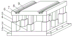
FIG. 1 is a schematic structural view of the present invention;
FIG. 2 is a schematic cross-sectional structure of the present invention;
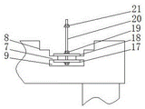
fig. 3 is a schematic view of the local cross-sectional structure of the present invention.
In the figure: 1. a base; 2. a connecting plate; 3. a first fixing lever; 4. a second fixing bar; 5. a third fixing bar; 6. mounting a plate; 7. a first clamping block; 8. a first groove; 9. a second groove; 10. a fourth fixing bar; 11. a third groove; 12. a spring; 13. a fourth groove; 14. a second fixture block; 15. a fifth groove; 16. a through groove; 17. a first clamping plate; 18. a second clamping plate; 19. a first nut; 20. a screw; 21. a second nut.
Detailed Description
The technical solutions in the embodiments of the present invention will be described clearly and completely with reference to the accompanying drawings in the embodiments of the present invention, and it is obvious that the described embodiments are only some embodiments of the present invention, not all embodiments. Based on the embodiments in the present invention, all other embodiments obtained by a person skilled in the art without creative work belong to the protection scope of the present invention.
In the description herein, it is to be understood that the terms "center," "upper," "lower," "front," "rear," "left," "right," "vertical," "horizontal," "top," "bottom," "inner," "outer," and the like are used in the orientations and positional relationships indicated in the drawings to facilitate the description of the patent and to simplify the description, but do not indicate or imply that the referenced device or element must have a particular orientation, be constructed and operated in a particular orientation, and thus are not to be considered limiting of the patent. In the description of the present application, it should be noted that unless otherwise explicitly stated or limited, the terms "mounted," "connected," and "disposed" are to be construed broadly and can, for example, be fixedly connected, disposed, detachably connected, disposed, or integrally connected and disposed. The specific meaning of the above terms in this patent may be understood by those of ordinary skill in the art as appropriate.
Referring to fig. 1-3, a fixing support for a heat pump comprises a base 1, four first fixing rods 3 which are uniformly distributed are fixedly installed at the top of the base 1, a third fixing rod 5 is arranged at the top of the first fixing rod 3, the base 1 and a mounting plate 6 are limited by the cooperation between the first fixing rod 3 and the third fixing rod 5, the mounting plate 6 is fixedly installed at the top of the third fixing rod 5, four second fixing rods 4 which are uniformly distributed are fixedly installed at the top of the base 1, a fourth fixing rod 10 is arranged at the top of the second fixing rod 4, the mounting plate 6 is damped by the cooperation between the second fixing rod 4 and the fourth fixing rod 10, so that the heat pump is prevented from vibrating during operation, thereby affecting production and life, the top of the fourth fixing rod 10 is fixedly connected with the bottom of the mounting plate 6, and connecting plates 2 are fixedly installed at the left side and the right side of the, the connecting plate 2 is internally provided with through grooves 16 which are uniformly distributed, the base 1 is fixed with the ground by matching between the connecting plate 2 and the through grooves 16, a fifth groove 15 is formed in the first fixing rod 3, the third fixing rod 5 penetrates into the first fixing rod 3 through the fifth groove 15, second clamping blocks 14 are fixedly arranged on two sides of the third fixing rod 5 and positioned in the first fixing rod 3, the fifth groove 15 is arranged for realizing the relative movement of the first fixing rod 3 and the third fixing rod 5, so as to damp the mounting plate 6, a fourth groove 13 is formed in the second fixing rod 4, the fourth fixing rod 10 penetrates into the second fixing rod 4 through the fourth groove 13, a third groove 11 is formed in the fourth fixing rod 10, a spring 12 is fixedly arranged in the third groove 11, and the bottom of the spring 12 is fixedly connected with the bottom of the fourth groove 13, the spring 12 is arranged to support the fourth fixing rod 10, the mounting plate 6 is supported by the fourth fixing rod 10, vibration of the heat pump is eliminated, the first groove 8 is formed in each of two sides of the top of the mounting plate 6, the second groove 9 is formed in the portion, located at the bottom of the first groove 8, of the mounting plate 6, the first clamping block 7 is fixedly mounted on each of two sides of the portion, located inside the second groove 9, the first groove 8 is used for clamping the bottom of the heat pump, stability is improved, the second clamping plate 18 and the first clamping plate 17 are arranged inside the second groove 9 and located above and below the first clamping block 7 respectively, the screw rods 20 are arranged in the first clamping plate 17 and the second clamping plate 18 in an inserting mode, the first nuts 19 are rotatably connected to the surfaces of the screw rods 20 and located above the second clamping plates 18, the second nuts 21 are rotatably connected to the surfaces of the screw rods 20 and located above the first nuts 19, and the first clamping, The first clamp plate 17 and the second clamp plate 18 are fixed inside the mounting plate 6 by the cooperation between the first nut 19 and the screw 20, and the heat pump is fixed by the screw 20 and the second nut 21.
During the use, with whole removal to required position, will wholly be fixed in the bottom surface through connecting plate 2 and logical groove 16, will install first cardboard 17, second cardboard 18, the inside of screw rod 20 installation to second recess 9 of first nut 19 and second nut 21, place first cardboard 17 and second cardboard 18 in the top and the below of first fixture block 7 respectively, top and bottom that are fixed in first fixture block 7 with first cardboard 17 and second cardboard 18 through first nut 19 and screw rod 20, place the heat pump in the top of mounting panel 6, it is fixed with the heat pump through screw rod 20 and second nut 21.
Although embodiments of the present invention have been shown and described, it will be appreciated by those skilled in the art that changes, modifications, substitutions and alterations can be made in these embodiments without departing from the principles and spirit of the invention, the scope of which is defined in the appended claims and their equivalents.
Claims (5)
1. The utility model provides a fixing support for heat pump, includes base (1), its characterized in that: the top fixed mounting of base (1) has four evenly distributed's first dead lever (3), the top of first dead lever (3) is provided with third dead lever (5), the top fixed mounting of third dead lever (5) has mounting panel (6), the top fixed mounting of base (1) has four evenly distributed's second dead lever (4), the top of second dead lever (4) is provided with fourth dead lever (10), the top of fourth dead lever (10) and the bottom fixed connection of mounting panel (6), the equal fixed mounting in the left and right sides of base (1) has connecting plate (2), evenly distributed's logical groove (16) have been seted up to the inside of connecting plate (2).
2. A fixing bracket for a heat pump according to claim 1, characterized in that: fifth groove (15) have been seted up to the inside of first dead lever (3), third dead lever (5) run through to the inside of first dead lever (3) through fifth groove (15), the equal fixed mounting in the inside that both sides and be located first dead lever (3) of third dead lever (5) has second fixture block (14).
3. A fixing bracket for a heat pump according to claim 1, characterized in that: fourth recess (13) have been seted up to the inside of second dead lever (4), fourth dead lever (10) run through to the inside of second dead lever (4) through fourth recess (13), third recess (11) have been seted up to the inside of fourth dead lever (10), the inside fixed mounting of third recess (11) has spring (12), the bottom of spring (12) and the bottom fixed connection of fourth recess (13).
4. A fixing bracket for a heat pump according to claim 1, characterized in that: first recess (8) have all been seted up to the both sides at mounting panel (6) top, second recess (9) have been seted up to the inside of mounting panel (6) and the bottom that is located first recess (8), the equal fixed mounting in both sides of second recess (9) inside has first fixture block (7).
5. The fixing bracket for a heat pump according to claim 4, wherein: the inside of second recess (9) and the top and the below that are located first fixture block (7) are provided with second cardboard (18) and first cardboard (17) respectively, the inside interlude of first cardboard (17) and second cardboard (18) is provided with screw rod (20), the surface of screw rod (20) and the top that is located second cardboard (18) rotate and are connected with first nut (19), the surface of screw rod (20) and the top that is located first nut (19) rotate and are connected with second nut (21).
Priority Applications (1)
| Application Number | Priority Date | Filing Date | Title |
|---|---|---|---|
| CN201921961702.0U CN211204494U (en) | 2019-11-14 | 2019-11-14 | Fixing support for heat pump |
Applications Claiming Priority (1)
| Application Number | Priority Date | Filing Date | Title |
|---|---|---|---|
| CN201921961702.0U CN211204494U (en) | 2019-11-14 | 2019-11-14 | Fixing support for heat pump |
Publications (1)
| Publication Number | Publication Date |
|---|---|
| CN211204494U true CN211204494U (en) | 2020-08-07 |
Family
ID=71881808
Family Applications (1)
| Application Number | Title | Priority Date | Filing Date |
|---|---|---|---|
| CN201921961702.0U Expired - Fee Related CN211204494U (en) | 2019-11-14 | 2019-11-14 | Fixing support for heat pump |
Country Status (1)
| Country | Link |
|---|---|
| CN (1) | CN211204494U (en) |
-
2019
- 2019-11-14 CN CN201921961702.0U patent/CN211204494U/en not_active Expired - Fee Related
Similar Documents
| Publication | Publication Date | Title |
|---|---|---|
| CN203584778U (en) | Diesel engine clean water pump mounting rack | |
| CN105207586A (en) | Fastening bracket for solar panel | |
| CN210685093U (en) | Quick installation mechanism of curtain | |
| CN211204494U (en) | Fixing support for heat pump | |
| CN103557422A (en) | Height-adjustable photovoltaic component bracket structure | |
| CN213508987U (en) | Window edge sealing fixing piece of assembled building external wall heat insulation integrated plate | |
| CN210587810U (en) | Automobile chassis welding support frame | |
| CN210927536U (en) | Photovoltaic module fixing device | |
| CN213329596U (en) | Energy-conserving curtain package assembly of type that takes precautions against earthquakes | |
| CN221467607U (en) | Photovoltaic solar panel convenient to installation | |
| CN213204613U (en) | High energy-saving open type aluminum plate curtain wall structure | |
| CN218911906U (en) | Install curtain fast | |
| CN215212107U (en) | Reinforced floor support | |
| CN218876883U (en) | Engineering machinery vehicle radiator mounting structure | |
| CN210564766U (en) | High-efficiency energy-saving diesel generator set | |
| CN221597808U (en) | Combined sun frame section bar | |
| CN213656885U (en) | Light and thin floor heating installation structure | |
| CN221030839U (en) | Light steel joist for mounting building curtain wall | |
| CN216313003U (en) | Solar panel hook rack | |
| CN218592743U (en) | Mechanical load clamp with sliding block and frameless assembly | |
| CN218023357U (en) | Oil field ground engineering is with thermal-insulated type storage tank mounting base | |
| CN210927553U (en) | Mounting component of double-glass photovoltaic module | |
| CN219710577U (en) | Connection structure of economical assembled curtain wall | |
| CN213576475U (en) | Electromechanical for engineering equipment fixing base | |
| CN219659623U (en) | Anti-seismic solar photovoltaic bracket |
Legal Events
| Date | Code | Title | Description |
|---|---|---|---|
| GR01 | Patent grant | ||
| GR01 | Patent grant | ||
| CF01 | Termination of patent right due to non-payment of annual fee | ||
| CF01 | Termination of patent right due to non-payment of annual fee |
Granted publication date: 20200807 Termination date: 20211114 |