CN211195316U - Thermal transfer printer for single pencil - Google Patents
Thermal transfer printer for single pencil Download PDFInfo
- Publication number
- CN211195316U CN211195316U CN201921394613.2U CN201921394613U CN211195316U CN 211195316 U CN211195316 U CN 211195316U CN 201921394613 U CN201921394613 U CN 201921394613U CN 211195316 U CN211195316 U CN 211195316U
- Authority
- CN
- China
- Prior art keywords
- pencil
- frame
- thermal transfer
- groove
- pen
- Prior art date
- Legal status (The legal status is an assumption and is not a legal conclusion. Google has not performed a legal analysis and makes no representation as to the accuracy of the status listed.)
- Active
Links
Images


Abstract
The utility model relates to a single thermal transfer printer for pencils, which comprises a frame, wherein a thermal transfer printing die head driven by an electric mechanism to lift is arranged on the frame, a lower rubber press block driven by a driving mechanism to slide transversely and reciprocally is arranged below the thermal transfer printing die head, and a transmission channel with a pattern film is arranged between the lower rubber press block and the thermal transfer printing die head; still be equipped with pencil feed mechanism in the frame, pencil feed mechanism is equipped with the push pedal that is used for transversely pushing away pen to rubber briquetting down on including the feed frame that is used for placing the pencil on the play pen mouth of feed frame. The pencil single-piece thermal transfer printer is simple in structure.
Description
Technical Field
The utility model relates to a single heat-transfer machine of pencil.
Background
The pencil is manufactured by printing a pattern on the outer periphery. The existing pencil transfer machine is unreasonable in structural design, difficult to use and has great limitation.
SUMMERY OF THE UTILITY MODEL
In view of the not enough of prior art, the utility model aims to solve the technical problem that a single heat transfer machine of pencil is provided, not only simple structure, convenient high efficiency moreover.
In order to solve the technical problem, the technical scheme of the utility model is that: a single pencil thermal transfer printer comprises a rack, wherein a thermal transfer printing die head driven to lift by an electric mechanism is arranged on the rack, a lower rubber pressing block driven by a driving mechanism to transversely slide in a reciprocating manner is arranged below the thermal transfer printing die head, and a transmission channel with a pattern film is arranged between the lower rubber pressing block and the thermal transfer printing die head; still be equipped with pencil feed mechanism in the frame, pencil feed mechanism is equipped with the push pedal that is used for transversely pushing away pen to rubber briquetting down on including the feed frame that is used for placing the pencil on the play pen mouth of feed frame.
Preferably, an upper rubber pressing block is fixedly arranged on the bottom surface of the thermal transfer printing die head.
Preferably, electric mechanism is including being located a mount in the frame, and the vertical ball screw that is equipped with through motor drive rotation on the mount, and the spiro union has ball nut on the ball screw, has linked firmly a switching piece on the ball nut, and the switching piece is connected with the heat-transfer die head through the vertical axis, has linked firmly the slider on the switching piece, the slide rail sliding fit of vertical extension on slider and the mount.
Preferably, a frame of the single-support heat transfer printing machine for the pencils is provided with a winding mechanism for winding a film with patterns, the winding mechanism comprises a movable frame positioned on the frame, a non-transfer printing film winding roller, a first rotating roller, a second rotating roller and a first tensioning roller set are sequentially arranged on one side of the heat transfer printing die head from top to bottom, and a second tensioning roller set, a third rotating roller and a driving rotating roller are sequentially arranged on the other side of the heat transfer printing die head from bottom to top; the first tensioning roller group and the second tensioning roller group are both composed of an upper tensioning roller and a lower tensioning roller; the film roll with the pattern is placed on a film winding roller without transfer printing, the end part of the film roll is wound on a first rotating roller, a second rotating roller and a first tensioning roller group in sequence, and then the film roll passes through a transmission channel and is wound on a second tensioning roller group and a third rotating roller in sequence, and a driving rotating roller is tightly pressed on the upper peripheral part of the third rotating roller and is used for providing transmission power of the film with the pattern; the winding modes of the patterned film on the upper tensioning roller and the lower tensioning roller are S-shaped winding.
Preferably, a plurality of arc-shaped sliding grooves are formed in the bottom mounting surface of the movable frame and are in screwed connection with the rack through vertical screws penetrating through the arc-shaped sliding grooves, the arc-shaped sliding grooves extend forwards and backwards, the rear side edge of the mounting surface extends out of the rack and is fixedly provided with a vertical connecting plate, fastening screws are symmetrically screwed on the left side and the right side of the vertical connecting plate, and the tail ends of the fastening screws are abutted against the rear side edge of the rack; be equipped with the lifter on the adjustable shelf between first commentaries on classics roller and the second commentaries on classics roller, the lifter rear end be equipped with the slider and with the adjustable shelf on the slide rail sliding fit of vertical extension, the lifter front end link firmly has the sensor that is used for responding to the black point between the adjacent pattern group on the pattern film, the lifter is through the vice drive lift of ball screw.
Preferably, the lower surface of the lower rubber press block is fixedly connected with a slide block, the slide block is in sliding fit with a slide rail extending transversely below the slide block, the driving mechanism is an oil cylinder or an air cylinder or a ball screw pair, a portal frame arranged on the frame is arranged above the lower rubber press block, an upper pressure spring piece and a front pressure spring piece which are positioned above the lower rubber press block are arranged on the portal frame, a rear straight baffle bar positioned above the lower rubber press block is arranged on the portal frame, and the rear straight baffle bar extends transversely; a push plate positioned between the lower rubber pressing block and the upper pressure spring is arranged inside the portal frame, a V-shaped groove is formed in the end part, facing the lower rubber pressing block, of the push plate, a rectangular groove is formed in the sharp end of the V-shaped groove, when a pencil is produced to be in a regular hexagon shape, the groove can be matched with the side part of the regular hexagon pencil, and is matched with three side lines of the regular hexagon side part, so that the pencil is effectively pushed out; the push plate is driven by a driving mechanism to transversely slide in a reciprocating manner, and the driving mechanism is an oil cylinder or an air cylinder or a ball screw pair; the width of the push plate is smaller than the maximum distance between the front pressure spring piece and the rear straight barrier strip; a material collecting hopper is arranged on one side, away from the push plate, of the lower rubber pressing block of the frame of the single pencil thermal transfer printing machine, and the inlet of the material collecting hopper is as high as the lower rubber pressing block.
Preferably, the feeding frame includes preceding curb plate and posterior lateral plate, and the distance is pencil length around preceding curb plate and the posterior lateral plate, and the groove that falls of vertical extension has set firmly on the lateral part that is close to rubber briquetting down between preceding curb plate and the posterior lateral plate, and the width that falls the groove is limited only in holding a pencil, and a plurality of pencils can be piled up to the height that falls the groove, and bottom between preceding curb plate and the posterior lateral plate sets firmly from last bottom plate down towards the slope of the groove that falls, and the low side of bottom plate links up with the top notch that falls the groove, go out the pen mouth and be located the bottom notch that falls the groove, has the clearance between the bottom notch that falls the groove and the frame upper surface, and the height in this clearance is greater than the external diameter of pencil, the push pedal is located this clearance department and transversely pushes away a motion through the.
Preferably, an arc-shaped inserting plate which is driven by a motor to swing is hinged to the outer side part, close to the lower rubber pressing block, of the pen dropping groove, the arc-shaped inserting plate is bent towards the pen dropping groove, the bottom end of the arc-shaped inserting plate is located beside the pen outlet, and the arc-shaped inserting plate is used for being inserted into the pen outlet when swinging towards the pen dropping groove; a through groove is formed in the middle of the bottom plate, a pen lifting plate driven to lift through an oil cylinder or an air cylinder is arranged on the through groove close to the low end of the pen falling groove, a rotating shaft driven to swing through a motor is arranged on the through groove far away from the high end of the pen falling groove, and a pen loosening plate located on the through groove is connected to the rotating shaft in a threaded mode.
Compared with the prior art, the utility model discloses following beneficial effect has: when the single-pencil thermal transfer printer is used, the pencil is pressed between the thermal transfer die head and the lower rubber pressing block, the patterned film is pressed between the thermal transfer die head and the pencil, the lower rubber pressing block transversely slides and drives the pencil to roll in the same direction, and the pattern of the patterned film is impressed on the periphery of the rolling pencil.
The present invention will be described in further detail with reference to the accompanying drawings and specific embodiments.
Drawings
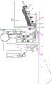
Fig. 1 is a schematic structural diagram of an embodiment of the present invention.
Fig. 2 is a schematic view of a partial structure according to an embodiment of the present invention.
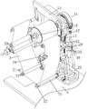
Fig. 3 is a perspective view of the winding mechanism.
Fig. 4 is a top view of the winding mechanism.
FIG. 5 is a perspective view of the lower rubber press block, the spring plate and the push plate.
Fig. 6 is a top view of fig. 5.
Fig. 7 is an enlarged view of a portion a of fig. 2.
FIG. 8 is a first schematic diagram illustrating the operation state of the transfer printing.
FIG. 9 is a second schematic diagram of the transfer operation.
Fig. 10 is a top view of fig. 7.
Fig. 11 is a sectional view taken along line B-B of fig. 10.
Fig. 12 is a top view of fig. 9.
FIG. 13 is a first schematic diagram of the construction of the pencil feeding mechanism.
FIG. 14 is a second schematic diagram of the construction of the pencil feeding mechanism.
FIG. 15 is a first schematic diagram of the feeding operation of the pencil.
Fig. 16 is a schematic diagram of the working state of feeding the pencil.
Detailed Description
In order to make the aforementioned and other features and advantages of the present invention comprehensible, embodiments accompanied with figures are described in detail below.
As shown in fig. 1 to 16, a single pencil thermal transfer printer comprises a frame, wherein a thermal transfer die head 1 driven by an electric mechanism to lift is arranged on the frame, a lower rubber pressing block 2 driven by a driving mechanism to transversely slide in a reciprocating manner is arranged below the thermal transfer die head, and a transmission channel with a pattern film 3 is arranged between the lower rubber pressing block and the thermal transfer die head; still be equipped with pencil feed mechanism 40 in the frame, pencil feed mechanism is including the feed frame that is used for placing the pencil, is equipped with the push pedal that is used for transversely pushing away the pen to rubber briquetting down on the mouth 41 of a pen of feed frame.
In the embodiment of the utility model, the bottom surface of the thermal transfer printing die head is fixedly provided with an upper rubber pressing block 4; during transfer printing, the pencil is pressed between the upper rubber pressing block and the lower rubber pressing block, and the patterned film is pressed between the upper rubber pressing block and the pencil.
The embodiment of the utility model provides an in, electric mechanism is including being located a mount 6 on frame 5, and the vertical ball screw 8 that is equipped with through motor 7 drive rotation on the mount, and the spiro union has ball nut 9 on the ball screw, has linked firmly a switching piece 10 on the ball nut, and the switching piece is connected with the heat-transfer die head through vertical axis 11, has linked firmly slider 12 on the switching piece, the slide rail 13 sliding fit of vertical extension on slider and the mount.
In the embodiment of the present invention, a frame of the single-support thermal transfer printer for pencils is provided with a winding mechanism 14 for winding a film with a pattern, the winding mechanism includes a movable frame 15 located on the frame, the movable frame is provided with a non-transfer film winding roller 16, a first rotating roller 17, a second rotating roller 18 and a first tensioning roller set from top to bottom in sequence on one side of the thermal transfer die head, and the movable frame is provided with a second tensioning roller set, a third rotating roller 19 and a driving rotating roller 20 from bottom to top in sequence on the other side of the thermal transfer die head; the first tensioning roller group and the second tensioning roller group are respectively composed of an upper tensioning roller 21 and a lower tensioning roller 22; the film roll with the pattern is placed on a film winding roller without transfer printing, the end part of the film roll is wound on a first rotating roller, a second rotating roller and a first tensioning roller group in sequence, and then the film roll passes through a transmission channel and is wound on a second tensioning roller group and a third rotating roller in sequence, and a driving rotating roller is tightly pressed on the upper peripheral part of the third rotating roller and is used for providing transmission power of the film with the pattern; the winding modes of the patterned film on the upper tensioning roller and the lower tensioning roller are S-shaped winding.
In the embodiment of the utility model, a plurality of arc chutes 24 are arranged on the bottom mounting surface 23 of the movable frame and are screwed on the frame through vertical screws 25 passing through the arc chutes, the arc chutes all extend forwards and backwards, the rear side edge of the mounting surface extends out of the frame and is fixedly provided with a vertical connecting plate 26, the left side and the right side of the vertical connecting plate are symmetrically screwed with fastening screws 27, and the tail ends of the fastening screws are pressed against the rear side edge of the frame; a lifting rod 28 is arranged on a movable frame between the first rotary roller and the second rotary roller, a slide block is arranged at the rear end of the lifting rod and is in sliding fit with a slide rail vertically extending on the movable frame, a sensor 29 used for sensing black points between adjacent pattern groups on the patterned film is fixedly connected to the front end of the lifting rod, and the lifting rod is driven to lift through a ball screw pair 30; the movable frame can adjust angles by driving all components on the movable frame, specifically, screws of the arc-shaped sliding grooves are loosened, the screwing amounts of the left and right fastening screws are respectively adjusted in a rotating manner, so that the movable frame can rotate to adjust the angles, and the screws are screwed in after the adjustment is finished; the lifting rod can adjust the position of the sensor up and down, the sensor senses black points, the patterned film is enabled to pause after being conveyed with a group of patterns, and the next group of patterns are conveyed after the group of patterns are transferred.
The embodiment of the utility model provides an in, lower rubber briquetting's lower surface has linked firmly the slider, slider and its lower horizontal extension's slide rail sliding fit, and actuating mechanism is hydro-cylinder or ball screw pair, lower rubber briquetting's top is equipped with a rack-mounted portal frame 31, installs last pressure spring 32, preceding pressure spring 33 that are located rubber briquetting top down on the portal frame, installs the straight blend stop 34 in the back that is located rubber briquetting top down on the portal frame, and the straight blend stop transversely extends in the back.
In the embodiment of the utility model, the inside of the portal frame is provided with a push plate 35 between the lower rubber pressing block and the upper pressure reed, the end part of the lower rubber pressing block, facing the push plate, is provided with a V-shaped slot 36, and a rectangular slot 37 is arranged in the sharp end of the V-shaped slot, when the produced pencil is in a regular hexagon shape, the slot can be matched with the side part of the regular hexagon pencil, and is matched with three side lines of the regular hexagon side part, so that the pencil can be effectively pushed out; the push plate is driven by a driving mechanism to transversely slide in a reciprocating manner, and the driving mechanism is an oil cylinder or an air cylinder or a ball screw pair.
The embodiment of the utility model provides an in, the width of push pedal is less than the biggest interval between preceding pressure spring and the straight blend stop in back.
The embodiment of the utility model provides an in, the frame of pencil list heat transfer machine is equipped with aggregate bin 38 in the one side that the push pedal was kept away from to rubber briquetting down, and the entry and the lower rubber briquetting height of aggregate bin are equal.
The embodiment of the utility model provides an in, the feeding frame includes preceding curb plate and posterior lateral plate 43, and the front-back interval of preceding curb plate and posterior lateral plate is pencil length, and the groove 44 that falls that has set firmly vertical extension on the lateral part that is close to down rubber briquetting between preceding curb plate and the posterior lateral plate, the width that falls the groove is limited only in holding a pencil, and a plurality of pencils can be piled up to the height that falls the groove, and bottom between preceding curb plate and the posterior lateral plate sets firmly bottom plate 45 from last down towards the slope of the groove that falls, and the low side of bottom plate links up with the top notch that falls the groove, go out the bottom notch that the pen mouth is located the groove that falls, has clearance 46 between the bottom notch that falls the groove and the frame upper surface, and the highly is greater than the external diameter of pencil in this clearance, the push pedal is located this clearance department and transversely pushes.
In the embodiment of the present invention, an arc-shaped insertion plate 47 driven by a motor to swing is hinged on the outer side of the pen dropping groove close to the lower rubber pressing block, the arc-shaped insertion plate is bent towards the pen dropping groove, and the bottom end of the arc-shaped insertion plate is located beside the pen outlet for inserting the pen outlet when swinging towards the pen dropping groove; a through groove 48 is formed in the middle of the bottom plate, a pen lifting plate 49 which is driven to lift through an oil cylinder or an air cylinder is arranged on the through groove at the low end close to the pen falling groove, a rotating shaft 50 which is driven to swing through a motor is arranged on the through groove at the high end far away from the pen falling groove, and a pen loosening plate 42 positioned on the through groove is connected to the rotating shaft in a threaded mode.
A working method of a single pencil thermal transfer printer comprises the following steps: when the pencil is used, the pencil is pressed between the thermal transfer printing die head and the lower rubber pressing block, the patterned film is pressed between the thermal transfer printing die head and the pencil, the lower rubber pressing block rolls along with the pencil in the same direction when transversely sliding, and the pattern of the patterned film is impressed on the periphery of the rolling pencil.
In the embodiment of the utility model, a plurality of pencils are firstly stacked in the feeding frame, wherein the rotating shaft fixedly connected with the pencil thinning plate can rotate up and down, so that the pencil thinning plate can swing up and down in the through groove, and the pencil thinning plate can disturb the pencils on the upper part of the pencil thinning plate to play the role of thinning the pencils; because the bottom plate inclines from top to bottom towards the pen falling groove, the pencils can fall into the pen falling groove one by one, the pencils in the pen falling groove are stacked up and down, and the pencils at the bottommost part are pressed on the upper surface of the rack at the pen outlet, namely the position of the gap 46. Before the push plate pushes a pencil, the arc-shaped inserting plate swings towards the direction of the pencil falling groove to enable the bottom end of the arc-shaped inserting plate to be inserted into the pencil outlet, the bottommost pencil is separated from the pencils on the arc-shaped inserting plate, the pencil lifting plate is lifted while the arc-shaped inserting plate is used for inserting the pencil, the lifted pencil lifting plate can share the weight of the pencil falling in the area of the pencil falling groove, and the phenomenon that the pencil skin is damaged when the arc-shaped inserting plate is used for inserting the pencil due to the fact that the pencil is pressed on. After the bottommost pencil is separated from the pencils on the bottommost pencil, the pushing plate pushes the bottommost pencil to the upper surface of the lower rubber pressing block; during transfer, the push plate pushes the pencil 39 to the side (left side) of the thermal transfer die head, the pencil is pushed to the upper surface of the lower rubber pressing block by the push plate, at the moment, the upper pressing reed presses the pencil on the upper surface of the lower rubber pressing block, the rear end of the pencil props against the rear straight blocking strip, the front end of the pencil is pressed by the front pressing reed, then the thermal transfer die head moves downwards until the upper rubber pressing block presses the upper pressing reed, the upper rubber pressing block simultaneously presses the pencil due to the fact that the upper rubber pressing block is soft and the upper pressing reed is thin, the pencil is pressed between the upper rubber pressing block and the lower rubber pressing block, and the film with the pattern is pressed between the upper rubber pressing block and the pencil to position the pencil and the; then the lower rubber pressing block transversely slides towards the left and carries the pencil to roll in the same direction, when the pencil rolls to a position just away from the upper pressing spring piece, the pattern is transferred until the pencil completely rolls to the left side of the upper rubber pressing block, and the pattern with the pattern film is impressed on the periphery of the rolling pencil; and then the thermal transfer printing die head moves upwards, the lower rubber pressing block continues to drive the transferred pencil to transversely slide leftwards to the inlet of the collecting hopper to stop, and the transferred pencil falls into the collecting hopper under the inertia effect.
The embodiment of the utility model provides an in, the pencil is decided by the stroke of pushing away of push pedal through the horizontal position of last pressure spring piece pressure on lower rubber briquetting, through the stroke of sliding that changes the push pedal, can adjust the pencil and press the horizontal position on lower rubber briquetting through last pressure spring piece to realize and cooperate with the pattern group position on the film with the pattern.
The embodiment of the utility model provides an in, this transfer machine also can be used to the gilt impression of pencil, and the replacement of taking the pattern film is the gilt membrane, and heat-transfer die head, the whole replacement of last rubber briquetting are the embossed seal of taking the pattern, and the pattern of embossed seal is down, and the theory of operation is on the same side, can carry out the gilt impression of pencil.
The present invention is not limited to the above preferred embodiments, and any one can obtain various forms of pencil single thermal transfer printer according to the teaching of the present invention. All the equivalent changes and modifications made according to the claims of the present invention shall fall within the scope of the present invention.
Claims (8)
1. A single pencil thermal transfer printer is characterized in that: the device comprises a frame, wherein a thermal transfer printing die head driven to lift by an electric mechanism is arranged on the frame, a lower rubber pressing block driven by a driving mechanism to transversely slide in a reciprocating manner is arranged below the thermal transfer printing die head, and a transmission channel with a pattern film is arranged between the lower rubber pressing block and the thermal transfer printing die head; still be equipped with pencil feed mechanism in the frame, pencil feed mechanism is equipped with the push pedal that is used for transversely pushing away pen to rubber briquetting down on including the feed frame that is used for placing the pencil on the play pen mouth of feed frame.
2. The pencil single thermal transfer printer according to claim 1, characterized in that: an upper rubber pressing block is fixedly arranged on the bottom surface of the thermal transfer printing die head.
3. The pencil single thermal transfer printer according to claim 1, characterized in that: the electric mechanism comprises a fixed frame positioned on the rack, a ball screw driven by a motor to rotate is vertically arranged on the fixed frame, a ball nut is screwed on the ball screw, a transfer block is fixedly connected onto the ball nut, the transfer block is connected with the heat transfer die head through a vertical shaft, a sliding block is fixedly connected onto the transfer block, and the sliding block is in sliding fit with a sliding rail vertically extending on the fixed frame.
4. The pencil single thermal transfer printer according to claim 1, characterized in that: the frame of the single-support thermal transfer printer for the pencils is provided with a winding mechanism used for winding a film with patterns, the winding mechanism comprises a movable frame positioned on the frame, the movable frame is sequentially provided with a non-transfer film winding roller, a first rotating roller, a second rotating roller and a first tensioning roller set from top to bottom on one side of a thermal transfer die head, and the movable frame is sequentially provided with a second tensioning roller set, a third rotating roller and a driving rotating roller from bottom to top on the other side of the thermal transfer die head; the first tensioning roller group and the second tensioning roller group are both composed of an upper tensioning roller and a lower tensioning roller; the film roll with the pattern is placed on a film winding roller without transfer printing, the end part of the film roll is wound on a first rotating roller, a second rotating roller and a first tensioning roller group in sequence, and then the film roll passes through a transmission channel and is wound on a second tensioning roller group and a third rotating roller in sequence, and a driving rotating roller is tightly pressed on the upper peripheral part of the third rotating roller and is used for providing transmission power of the film with the pattern; the winding modes of the patterned film on the upper tensioning roller and the lower tensioning roller are S-shaped winding.
5. The pencil single thermal transfer printer according to claim 4, characterized in that: a plurality of arc-shaped sliding grooves are formed in a mounting surface at the bottom of the movable frame and are in screwed connection with the rack through vertical screws penetrating through the arc-shaped sliding grooves, the arc-shaped sliding grooves extend forwards and backwards, the rear side edge of the mounting surface extends out of the rack and is fixedly provided with a vertical connecting plate, fastening screws are symmetrically screwed on the left side and the right side of the vertical connecting plate, and the tail ends of the fastening screws are abutted against the rear side edge of the rack; be equipped with the lifter on the adjustable shelf between first commentaries on classics roller and the second commentaries on classics roller, the lifter rear end be equipped with the slider and with the adjustable shelf on the slide rail sliding fit of vertical extension, the lifter front end link firmly has the sensor that is used for responding to the black point between the adjacent pattern group on the pattern film, the lifter is through the vice drive lift of ball screw.
6. The pencil single thermal transfer printer according to claim 1, characterized in that: the lower surface of the lower rubber pressing block is fixedly connected with a sliding block, the sliding block is in sliding fit with a sliding rail extending transversely below the sliding block, the driving mechanism is an oil cylinder or an air cylinder or a ball screw pair, a portal frame arranged on the frame is arranged above the lower rubber pressing block, an upper pressure spring piece and a front pressure spring piece which are positioned above the lower rubber pressing block are arranged on the portal frame, a rear straight baffle bar positioned above the lower rubber pressing block is arranged on the portal frame, and the rear straight baffle bar extends transversely; a push plate positioned between the lower rubber pressing block and the upper pressure spring is arranged inside the portal frame, a V-shaped groove is formed in the end part, facing the lower rubber pressing block, of the push plate, a rectangular groove is formed in the sharp end of the V-shaped groove, when a pencil is produced to be in a regular hexagon shape, the groove can be matched with the side part of the regular hexagon pencil, and is matched with three side lines of the regular hexagon side part, so that the pencil is effectively pushed out; the push plate is driven by a driving mechanism to transversely slide in a reciprocating manner, and the driving mechanism is an oil cylinder or an air cylinder or a ball screw pair; the width of the push plate is smaller than the maximum distance between the front pressure spring piece and the rear straight barrier strip; a material collecting hopper is arranged on one side, away from the push plate, of the lower rubber pressing block of the frame of the single pencil thermal transfer printing machine, and the inlet of the material collecting hopper is as high as the lower rubber pressing block.
7. The pencil single thermal transfer printer according to claim 1, characterized in that: the feeding frame includes preceding curb plate and posterior lateral plate, and the distance is pencil length around preceding curb plate and the posterior lateral plate, and the pen groove that falls of vertical extension has set firmly on the lateral part that is close to down rubber briquetting between preceding curb plate and the posterior lateral plate, and the width that falls the pen groove is limited only to holding a pencil, and a plurality of pencils can be piled up to the height that falls the pen groove, and bottom between preceding curb plate and the posterior lateral plate sets firmly from last bottom plate down towards the slope of the pen groove that falls, and the low side of bottom plate links up with the top notch that falls the pen groove, it is located the bottom notch that falls the pen groove to go out the mouth, has the clearance between the bottom notch that falls the pen groove and the frame upper surface, and the highly external diameter that is greater than the pencil in this clearance, the push pedal is located this clearance department.
8. The pencil single thermal transfer printer according to claim 7, wherein: the outer side part of the pen dropping groove, which is close to the lower rubber pressing block, is hinged with an arc-shaped inserting plate which is driven by a motor to swing, the arc-shaped inserting plate is bent towards the pen dropping groove, the bottom end of the arc-shaped inserting plate is positioned beside the pen outlet and is used for being inserted into the pen outlet when swinging towards the pen dropping groove; a through groove is formed in the middle of the bottom plate, a pen lifting plate driven to lift through an oil cylinder or an air cylinder is arranged on the through groove close to the low end of the pen falling groove, a rotating shaft driven to swing through a motor is arranged on the through groove far away from the high end of the pen falling groove, and a pen loosening plate located on the through groove is connected to the rotating shaft in a threaded mode.
Priority Applications (1)
| Application Number | Priority Date | Filing Date | Title |
|---|---|---|---|
| CN201921394613.2U CN211195316U (en) | 2019-08-27 | 2019-08-27 | Thermal transfer printer for single pencil |
Applications Claiming Priority (1)
| Application Number | Priority Date | Filing Date | Title |
|---|---|---|---|
| CN201921394613.2U CN211195316U (en) | 2019-08-27 | 2019-08-27 | Thermal transfer printer for single pencil |
Publications (1)
| Publication Number | Publication Date |
|---|---|
| CN211195316U true CN211195316U (en) | 2020-08-07 |
Family
ID=71882730
Family Applications (1)
| Application Number | Title | Priority Date | Filing Date |
|---|---|---|---|
| CN201921394613.2U Active CN211195316U (en) | 2019-08-27 | 2019-08-27 | Thermal transfer printer for single pencil |
Country Status (1)
| Country | Link |
|---|---|
| CN (1) | CN211195316U (en) |
Cited By (1)
| Publication number | Priority date | Publication date | Assignee | Title |
|---|---|---|---|---|
| CN110356104A (en) * | 2019-08-27 | 2019-10-22 | 福州普洛机械制造有限公司 | Pencil list branch heat transfer machine and its working method |
-
2019
- 2019-08-27 CN CN201921394613.2U patent/CN211195316U/en active Active
Cited By (2)
| Publication number | Priority date | Publication date | Assignee | Title |
|---|---|---|---|---|
| CN110356104A (en) * | 2019-08-27 | 2019-10-22 | 福州普洛机械制造有限公司 | Pencil list branch heat transfer machine and its working method |
| CN110356104B (en) * | 2019-08-27 | 2023-07-28 | 福州普洛机械制造有限公司 | Pencil single-branch heat transfer machine and working method thereof |
Similar Documents
| Publication | Publication Date | Title |
|---|---|---|
| CN110356104B (en) | Pencil single-branch heat transfer machine and working method thereof | |
| CN202016254U (en) | Novel rotary screen printing machine | |
| CN211195316U (en) | Thermal transfer printer for single pencil | |
| CN107097580B (en) | Thermoprinting toy processing technology and processing equipment thereof | |
| CN208197801U (en) | Intermittent flat screen process press | |
| CN208746437U (en) | Paper packing apparatus | |
| CN211195317U (en) | Pencil transfer mechanism | |
| CN1087224C (en) | Web rotary press | |
| CN213322237U (en) | Packing box printing device with scribble black function fast | |
| CN202130136U (en) | Hand-operated fine tuning cloth pressing mechanism | |
| CN210312805U (en) | Inclined sheet material receiving device for screen printing machine | |
| CN112616981B (en) | Automatic caramel treats production device for food production | |
| CN201049538Y (en) | Pulling device for screen process press | |
| CN215512493U (en) | Pressing assembly for producing printing cartons | |
| CN101648455B (en) | Transfer-receiving mechanism of sheet fed press | |
| CN220841877U (en) | Novel square sheet positioning gilding press | |
| CN207105834U (en) | The printing equipment of plastic gravure machine | |
| CN213428033U (en) | Moon cake forming machine | |
| CN214164514U (en) | Paper roll support for electronic surface single machine | |
| CN214495132U (en) | Material collecting device of paper printing machine | |
| CN211254067U (en) | Main conveying mechanism of book type box machine | |
| CN215751029U (en) | Paper flattening device on carton printing production line | |
| CN216235035U (en) | High-speed paper feeder of flat-bed printing machine | |
| CN214692447U (en) | Cloth raw material releasing device for cloth printing | |
| CN219903758U (en) | Material saving device for auxiliary materials |
Legal Events
| Date | Code | Title | Description |
|---|---|---|---|
| GR01 | Patent grant | ||
| GR01 | Patent grant |