CN211193715U - Precise electronic servo press-mounting machine - Google Patents
Precise electronic servo press-mounting machine Download PDFInfo
- Publication number
- CN211193715U CN211193715U CN201922347668.4U CN201922347668U CN211193715U CN 211193715 U CN211193715 U CN 211193715U CN 201922347668 U CN201922347668 U CN 201922347668U CN 211193715 U CN211193715 U CN 211193715U
- Authority
- CN
- China
- Prior art keywords
- fixed
- baffle
- plate
- servo motor
- mounting plate
- Prior art date
- Legal status (The legal status is an assumption and is not a legal conclusion. Google has not performed a legal analysis and makes no representation as to the accuracy of the status listed.)
- Expired - Fee Related
Links
Images


Abstract
The utility model discloses an accurate electronic servo press-mounting machine, which comprises a box body, a concave working table, a mounting plate, a servo motor, a first synchronous wheel, a thread lifting device, a second synchronous wheel, a pressure head, a fixed station, a control panel and a programmable touch screen, wherein one side of the middle part of the box body is provided with the concave working table, the upper end of the inner wall of the box body is fixed with the mounting plate, one end of the lower surface of the mounting plate is fixed with the servo motor, the output end of the servo motor passes through the mounting plate and is fixed with the first synchronous wheel, the end of the mounting plate, which is far away from the servo motor, is provided with the thread lifting device, the input end of the thread lifting device passes through the mounting plate and is fixed with the second synchronous wheel, the first synchronous wheel and the second synchronous wheel are connected through synchronous belt transmission, the output end of the thread lifting device, and the distance between the two second baffles can be adjusted according to the size of the pressing tool, so that the pressing tool is convenient for people to use.
Description
Technical Field
The utility model relates to a servo pressure equipment machine technical field specifically is a servo pressure equipment machine of accurate electron.
Background
Servo pressure equipment machine is the machine of an auxiliary component pressfitting assembly, and it is rotatory to drive pressure device's input through servo motor, rotates through rotatory screw lead screw and makes pressure device's output remain the motion, and the cooperation pressure head comes to carry out the pressfitting to the part, but current pressure equipment machine is not convenient for fixed to the pressfitting frock, and the pressfitting frock of the people of not being convenient for according to equidimension not adjusts. Therefore, a precise electronic servo press-mounting machine is provided.
SUMMERY OF THE UTILITY MODEL
An object of the utility model is to provide a servo pressure equipment machine of accurate electron to solve the problem that proposes among the above-mentioned background art.
In order to achieve the above object, the utility model provides a following technical scheme: the utility model provides a precision electronic servo press-mounting machine, includes box, concave station, mounting panel, servo motor, first synchronizing wheel, screw thread elevating gear, second synchronizing wheel, pressure head, fixed station, control panel and touch screen able to programme, box middle part one side is equipped with the concave station of working, box inner wall upper end is fixed with the mounting panel, mounting panel lower surface one end is fixed with servo motor, servo motor's output passes the mounting panel and is fixed with first synchronizing wheel, the mounting panel is kept away from servo motor's one end and is installed screw thread elevating gear, screw thread elevating gear's input passes the mounting panel and is fixed with the second synchronizing wheel, and first synchronizing wheel and second synchronizing wheel pass through synchronous belt drive and connect, screw thread elevating gear's output passes the concave station top of working and is fixed with the pressure head, the concave station inner wall of working is fixed with the fixed station, box one side is fixed with control panel and touch screen able to programme, and the servo motor is respectively and electrically connected with the control panel and the programmable touch screen.
Preferably, the fixed station comprises a fixed plate, a first baffle, a first side plate, a threaded rod, a second baffle, a knob, a second side plate, an electric push rod and a third baffle, a fixed plate is fixed on the inner wall of the working concave table, a first baffle is fixed at one end of the upper surface of the fixed plate, a first side plate is symmetrically fixed at one end of the upper surface of the fixing plate close to the first baffle plate, a threaded hole is arranged in the middle of the first side plate, a threaded rod is connected with the middle part of the first side plate in a threaded manner, one end of the threaded rod is rotationally connected with a second baffle plate through a bearing, a knob is fixed at one end of the threaded rod, which is far away from the second baffle plate, a second side plate is fixed at one end of the upper surface of the fixing plate, which is far away from the first baffle plate, an electric push rod is embedded and fixed in the middle of the second side plate, a third baffle is fixed at the output end of the electric push rod, and the electric push rod is electrically connected with the control panel and the programmable touch screen.
Preferably, guide rods are symmetrically fixed to two ends of the third baffle and are in sliding connection with the second side plate through guide sleeves.
Preferably, the two sides of one end, close to the concave working table, of the box body are symmetrically fixed with protective covers.
Preferably, the bottom of the box body is symmetrically fixed with casters with support.
Preferably, the top of the first baffle is provided with a scale.
Preferably, the upper surface of the fixing plate is symmetrically provided with T-shaped sliding grooves, the bottom of the second baffle plate is symmetrically fixed with T-shaped sliding blocks matched with the T-shaped sliding grooves, and the T-shaped sliding blocks are slidably connected with the T-shaped sliding grooves.
Preferably, the servo motor is a speed reduction motor.
Preferably, an alarm lamp is fixed on one side of the box body and electrically connected with the programmable touch screen.
Compared with the prior art, the beneficial effects of the utility model are that:
1. the utility model discloses: when the pressing tool is used, a user rotates the knob according to the size of the pressing tool, so as to drive the threaded rod to rotate, the threaded rod drives the second baffles to be close to each other, the position of the second baffles to be moved is accurately controlled through the scales on the first baffles, the distance between the two second baffles is equal to the width of the pressing tool, the pressing tool can be placed on the fixing plate and clamped between the two second baffles, the user controls the electric push rod to move through the control panel, so as to drive the third baffle to move, the third baffle pushes the pressing tool to move to one side of the first baffle, so that the pressing tool is clamped between the first baffle and the third baffle, the pressing tool is limited, the user controls the servo motor to rotate through the control panel, and drives the thread lifting device to move through the first synchronizing wheel and the second synchronizing wheel, the pressing head is driven to carry out pressing work on the part on the pressing tool, people can conveniently limit and fix the pressing tool, the distance between the two second baffles can be adjusted according to the size of the pressing tool, and the pressing tool is convenient for people to use.
Drawings
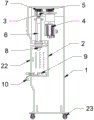
FIG. 1 is a schematic view of the overall front view structure of the present invention;
FIG. 2 is a schematic side sectional view of the present invention;
fig. 3 is a schematic structural view of the fixing table of the present invention.
In the figure: 1. a box body; 2. a working concave platform; 3. mounting a plate; 4. a servo motor; 5. a first synchronizing wheel; 6. a screw thread lifting device; 7. a second synchronizing wheel; 8. a pressure head; 9. a fixed table; 10. a control panel; 11. a programmable touch screen; 12. a fixing plate; 13. a first baffle plate; 14. a first side plate; 15. a threaded rod; 16. a second baffle; 17. a knob; 18. a second side plate; 19. an electric push rod; 20. a third baffle plate; 21. a guide bar; 22. a protective cover; 23. a belt supporting caster; 24. a T-shaped chute; 25. warning light, 26, safety light grating.
Detailed Description
The technical solutions in the embodiments of the present invention will be described clearly and completely with reference to the accompanying drawings in the embodiments of the present invention, and it is obvious that the described embodiments are only some embodiments of the present invention, not all embodiments. Based on the embodiments in the present invention, all other embodiments obtained by a person skilled in the art without creative work belong to the protection scope of the present invention.
Referring to fig. 1-3, the present invention provides a technical solution: the utility model provides a precision electronic servo press-mounting machine, includes box 1, work concave station 2, mounting panel 3, servo motor 4, first synchronizing wheel 5, screw thread elevating gear 6, second synchronizing wheel 7, pressure head 8, fixed station 9, control panel 10 and touch screen 11 able to programme, box 1 middle part one side is equipped with work concave station 2, box 1 inner wall upper end is fixed with mounting panel 3, mounting panel 3 lower surface one end is fixed with servo motor 4, the output of servo motor 4 passes mounting panel 3 and is fixed with first synchronizing wheel 5, the one end that servo motor 4 was kept away from to mounting panel 3 is installed screw thread elevating gear 6, the input of screw thread elevating gear 6 passes mounting panel 3 and is fixed with second synchronizing wheel 7, and first synchronizing wheel 5 and second synchronizing wheel 7 pass through synchronous belt drive and connect, the output of screw thread elevating gear 6 passes the pressure head and is fixed with 8 at work concave station 2 top, the inner wall of the working concave table 2 is fixed with a fixed table 9, one side of the box body 1 is fixed with a control panel 10 and a programmable touch screen 11, and the servo motor 4 is respectively electrically connected with the control panel 10 and the programmable touch screen 11.
The fixing table 9 comprises a fixing plate 12, a first baffle 13, a first side plate 14, a threaded rod 15, a second baffle 16, a knob 17, a second side plate 18, an electric push rod 19 and a third baffle 20, the inner wall of the concave worktable 2 is fixed with the fixing plate 12, one end of the upper surface of the fixing plate 12 is fixed with the first baffle 13, one end of the upper surface of the fixing plate 12 close to the first baffle 13 is symmetrically fixed with the first side plate 14, the middle part of the first side plate 14 is provided with a threaded hole, the middle part of the first side plate 14 is in threaded connection with the threaded rod 15, one end of the threaded rod 15 is in rotary connection with the second baffle 16 through a bearing, one end of the threaded rod 15 far away from the second baffle 16 is fixed with the knob 17, one end of the upper surface of the fixing plate 12 far away from the first baffle 13 is fixed with the second side plate 18, the middle part of the second side plate 18 is embedded and, the electric push rod 19 is electrically connected with the control panel 10 and the programmable touch screen 11, so that the pressing tool is limited and fixed conveniently.
Two sides of one end of the box body 1 close to the working concave platform 2 are symmetrically fixed with protective covers 22 to prevent parts from splashing caused by machine faults, and the protective covers are also provided with safety gratings 26.
The bottom of the box body 1 is symmetrically fixed with supporting casters 23, which is convenient for the box body 1 to move.
The top of the first baffle 13 is provided with scales, so that the moving precision of the second baffle 16 is improved.
T-shaped sliding grooves 24 are symmetrically formed in the upper surface of the fixing plate 12, T-shaped sliding blocks matched with the T-shaped sliding grooves 24 are symmetrically fixed to the bottom of the second baffle plate 16, and the T-shaped sliding blocks are connected with the T-shaped sliding grooves 24 in a sliding mode, so that the second baffle plate 16 is limited.
The servo motor 4 is a speed reducing motor, and the output rotating speed of the servo motor 4 is convenient to reduce.
An alarm lamp 25 is fixed on one side of the box body 1, and the alarm lamp 25 is electrically connected with the programmable touch screen 11, so that an alarm can be sent out when a machine fails.
The working principle is as follows: when in use, a user rotates the knob 17 according to the size of the pressing tool, and then drives the threaded rod 15 to rotate, so that the threaded rod 15 drives the second baffles 16 to approach each other, and the position of the second baffles 16 is accurately controlled by the scale on the first baffle 13, so that the distance between the two second baffles 16 is equal to the width of the pressing tool, at this time, the user can place the pressing tool on the fixing plate 12 and clamp between the two second baffles 16, at this time, the user controls the electric push rod 19 to move through the control panel 10, and then drives the third baffle 20 to move, so that the third baffle 20 pushes the pressing tool to move to one side of the first baffle 13, so that the pressing tool is clamped between the first baffle 13 and the third baffle 20, and limits the pressing tool, at this time, the user controls the servo motor 4 to rotate through the control panel 10, and drives the threaded lifting device 6 to move through the first synchronizing wheel 5 and the second synchronizing wheel 7, and the thread lifting device 6 of the press-fitting machine is a prior art that has been disclosed, and will not be described here, and drives the press head 8 to perform press-fitting work on the parts on the press-fitting tool.
It is noted that, herein, relational terms such as first and second, and the like may be used solely to distinguish one entity or action from another entity or action without necessarily requiring or implying any actual such relationship or order between such entities or actions. Also, the terms "comprises," "comprising," or any other variation thereof, are intended to cover a non-exclusive inclusion, such that a process, method, article, or apparatus that comprises a list of elements does not include only those elements but may include other elements not expressly listed or inherent to such process, method, article, or apparatus.
Although embodiments of the present invention have been shown and described, it will be appreciated by those skilled in the art that changes, modifications, substitutions and alterations can be made in these embodiments without departing from the principles and spirit of the invention, the scope of which is defined in the appended claims and their equivalents.
Claims (9)
1. The utility model provides a servo pressure equipment machine of accurate electron, includes box (1), work concave station (2), mounting panel (3), servo motor (4), first synchronizing wheel (5), screw thread elevating gear (6), second synchronizing wheel (7), pressure head (8), fixed station (9), control panel (10) and touch-control screen (11) able to programme, its characterized in that: the improved structure of the touch screen is characterized in that a working concave table (2) is arranged on one side of the middle of the box body (1), a mounting plate (3) is fixed to the upper end of the inner wall of the box body (1), a servo motor (4) is fixed to one end of the lower surface of the mounting plate (3), a first synchronizing wheel (5) is fixed to the output end of the servo motor (4) after passing through the mounting plate (3), a thread lifting device (6) is installed at one end, far away from the servo motor (4), of the mounting plate (3), the input end of the thread lifting device (6) penetrates through the mounting plate (3) and is fixed with a second synchronizing wheel (7), the first synchronizing wheel (5) and the second synchronizing wheel (7) are connected through synchronous belt transmission, a pressure head (8) is fixed to the top of the working concave table (2), a fixed table (9) is fixed to the inner wall of the working concave table (2), a control panel (10) and a programmable, and the servo motor (4) is respectively electrically connected with the control panel (10) and the programmable touch screen (11).
2. The precision electronic servo press-fitting machine according to claim 1, wherein: fixed station (9) is including fixed plate (12), first baffle (13), first curb plate (14), threaded rod (15), second baffle (16), knob (17), second curb plate (18), electric putter (19) and third baffle (20), work concave station (2) inner wall is fixed with fixed plate (12), fixed plate (12) upper surface one end is fixed with first baffle (13), the one end symmetry that fixed plate (12) upper surface is close to first baffle (13) is fixed with first curb plate (14), threaded hole is seted up at first curb plate (14) middle part, threaded connection has threaded rod (15) in first curb plate (14) middle part, threaded rod (15) one end is rotated through the bearing and is connected with second baffle (16), the one end that second baffle (16) were kept away from in threaded rod (15) is fixed with knob (17), the one end that first baffle (13) was kept away from to fixed plate (12) upper surface is fixed with second baffle (18) The middle of the second side plate (18) is fixedly embedded with an electric push rod (19), the output end of the electric push rod (19) is fixedly provided with a third baffle (20), and the electric push rod (19) is electrically connected with the control panel (10) and the programmable touch screen (11).
3. The precision electronic servo press-fitting machine according to claim 2, wherein: guide rods (21) are symmetrically fixed at two ends of the third baffle (20), and the guide rods (21) are connected with the second side plate (18) in a sliding mode through guide sleeves.
4. The precision electronic servo press-fitting machine according to claim 1, wherein: and protective covers (22) are symmetrically fixed on two sides of one end, close to the working concave table (2), of the box body (1).
5. The precision electronic servo press-fitting machine according to claim 1, wherein: the bottom of the box body (1) is symmetrically fixed with supporting caster wheels (23).
6. The precision electronic servo press-fitting machine according to claim 2, wherein: the top of the first baffle (13) is provided with scales.
7. The precision electronic servo press-fitting machine according to claim 2, wherein: t-shaped sliding grooves (24) are symmetrically formed in the upper surface of the fixing plate (12), T-shaped sliding blocks matched with the T-shaped sliding grooves (24) are symmetrically fixed to the bottom of the second baffle (16), and the T-shaped sliding blocks are connected with the T-shaped sliding grooves (24) in a sliding mode.
8. The precision electronic servo press-fitting machine according to claim 1, wherein: the servo motor (4) is a speed reducing motor.
9. The precision electronic servo press-fitting machine according to claim 1, wherein: and an alarm lamp (25) is fixed on one side of the box body (1), and the alarm lamp (25) is electrically connected with the programmable touch screen (11).
Priority Applications (1)
| Application Number | Priority Date | Filing Date | Title |
|---|---|---|---|
| CN201922347668.4U CN211193715U (en) | 2019-12-24 | 2019-12-24 | Precise electronic servo press-mounting machine |
Applications Claiming Priority (1)
| Application Number | Priority Date | Filing Date | Title |
|---|---|---|---|
| CN201922347668.4U CN211193715U (en) | 2019-12-24 | 2019-12-24 | Precise electronic servo press-mounting machine |
Publications (1)
| Publication Number | Publication Date |
|---|---|
| CN211193715U true CN211193715U (en) | 2020-08-07 |
Family
ID=71863386
Family Applications (1)
| Application Number | Title | Priority Date | Filing Date |
|---|---|---|---|
| CN201922347668.4U Expired - Fee Related CN211193715U (en) | 2019-12-24 | 2019-12-24 | Precise electronic servo press-mounting machine |
Country Status (1)
| Country | Link |
|---|---|
| CN (1) | CN211193715U (en) |
-
2019
- 2019-12-24 CN CN201922347668.4U patent/CN211193715U/en not_active Expired - Fee Related
Similar Documents
| Publication | Publication Date | Title |
|---|---|---|
| CN217891171U (en) | Cable protection pipe cutting device with end face detection function | |
| CN211193715U (en) | Precise electronic servo press-mounting machine | |
| CN213729980U (en) | Laser cutting equipment for touch screen of mobile phone | |
| CN212918442U (en) | Numerical control machine tool capable of adjusting angle of placing platform | |
| CN211490682U (en) | Numerical control automatic fixed length positioning frame of aluminum profile cutting machine | |
| CN211828458U (en) | Pressing device of silicon steel sheet for electric welding machine | |
| CN210788806U (en) | Pneumatic punching device for production of prepuce cutter | |
| CN211465010U (en) | Tubular product cutting device for construction | |
| CN207564112U (en) | A kind of numerically-controlled machine tool equipment with multifunctional base | |
| CN208196908U (en) | A kind of gate plate cutting device | |
| CN218837751U (en) | Automatic marking device suitable for steel sheet processing | |
| CN210209837U (en) | Polishing equipment for metal processing machinery | |
| CN211639431U (en) | Glass apron hole processingequipment | |
| CN211464837U (en) | Special numerical control plane turning equipment | |
| CN216227051U (en) | Fixed stable high accuracy metal frame drilling machine | |
| CN219521583U (en) | Polishing device for processing equipotential tester shell | |
| CN219188863U (en) | Revolving stage drive shaft backup pad cutting frock | |
| CN113152066B (en) | Quick fixed-distance cutting device for processing isolation clothes and cutting method thereof | |
| CN210060340U (en) | Press mounting equipment for machining automobile shock absorber | |
| CN218080710U (en) | Cutting device for processing | |
| CN213033918U (en) | Numerical control programming aluminum alloy laser cutting device | |
| CN214265794U (en) | Processing fixing device of sealing strip for protective door | |
| CN220575223U (en) | Cutting device for metal products | |
| CN211360833U (en) | Efficient cutting device for gear machining | |
| CN215356749U (en) | Glasses accessory laser cutting machine |
Legal Events
| Date | Code | Title | Description |
|---|---|---|---|
| GR01 | Patent grant | ||
| GR01 | Patent grant | ||
| CF01 | Termination of patent right due to non-payment of annual fee |
Granted publication date: 20200807 Termination date: 20211224 |
|
| CF01 | Termination of patent right due to non-payment of annual fee |