CN211192976U - Excavator pump body processing is with adding fast and holding anchor clamps - Google Patents
Excavator pump body processing is with adding fast and holding anchor clamps Download PDFInfo
- Publication number
- CN211192976U CN211192976U CN201921998088.5U CN201921998088U CN211192976U CN 211192976 U CN211192976 U CN 211192976U CN 201921998088 U CN201921998088 U CN 201921998088U CN 211192976 U CN211192976 U CN 211192976U
- Authority
- CN
- China
- Prior art keywords
- waist
- block
- sliding
- pump body
- shaped groove
- Prior art date
- Legal status (The legal status is an assumption and is not a legal conclusion. Google has not performed a legal analysis and makes no representation as to the accuracy of the status listed.)
- Expired - Fee Related
Links
Images


Landscapes
- Structures Of Non-Positive Displacement Pumps (AREA)
Abstract
The utility model discloses a rapid clamping fixture for processing an excavator pump body, which comprises a bottom plate, wherein the upper side surface of the bottom plate is provided with a plurality of transverse and vertical chutes, the interiors of the chutes are all provided with a first waist-shaped groove, the lower part of the bottom plate is connected with a lifting plate in a sliding way through a driving component, the lifting plate is provided with a plurality of second waist-shaped grooves, the interior of the first waist-shaped groove is connected with a slide block in a sliding way, a clamping block is connected on the slide block in a sliding way along the horizontal direction, a trapezoidal block is connected on the slide block in a sliding way, the side wall of the trapezoidal block is provided with a third waist-shaped groove, the interior of the third waist-shaped groove is connected with a bolt in a sliding way, and the lower end of the bolt sequentially penetrates through the slide block, the first waist-shaped groove and the second waist-shaped groove, the efficiency of the clamping work is improved.
Description
Technical Field
The utility model relates to an excavator pump body anchor clamps technical field specifically is an excavator pump body processing is with adding anchor clamps fast.
Background
The excavator pump body is suitable for different excavator models, various different types of pump bodies are produced, new products can be continuously developed in order to save cost and continuously improve the structure of the pump body, the appearance structure of different products can be greatly different, so different clamps are required to adapt to the production of different products, the clamp cost can be increased by one clamp for one product, the clamp manufacturing period is required, the clamps also need to be integrally replaced when the products are replaced, time and labor are wasted, and the working efficiency is also influenced; in addition, the traditional fixing clamp for the excavator pump body cannot realize the fixed clamping of the excavator pump bodies to be machined in different sizes in different directions by adopting simple operation, so that the rapid clamping clamp for machining the excavator pump body is provided.
SUMMERY OF THE UTILITY MODEL
An object of the utility model is to provide an excavator pump body processing is with adding fast and holding anchor clamps to solve the problem that proposes among the above-mentioned background art.
In order to achieve the above object, the utility model provides a following technical scheme: a rapid clamping fixture for machining a pump body of an excavator comprises a bottom plate, wherein a plurality of transverse and vertical sliding grooves are formed in the upper side surface of the bottom plate, first waist-shaped grooves are formed in the sliding grooves, a lifting plate is connected to the lower side of the bottom plate in a sliding mode through a driving assembly, a plurality of second waist-shaped grooves are formed in the lifting plate, each second waist-shaped groove corresponds to the corresponding first waist-shaped groove one by one, a sliding block is connected to the inside of each first waist-shaped groove in a sliding mode, a clamping block is connected to the sliding block in a sliding mode in the horizontal direction, a chute is formed in the sliding block, a trapezoidal block is connected to the sliding block in a sliding mode in the direction of the chute, the inclined surface of the trapezoidal block is movably connected with the clamping block, a third waist-shaped groove is formed in the side wall of the trapezoidal block, a bolt is connected to the inside the third waist-shaped groove in a sliding mode, and a hexagon, and the hexagonal nut is clamped on the upper side wall of the trapezoidal block, and the lower end of the bolt sequentially penetrates through the sliding block, the first waist-shaped groove and the second waist-shaped groove and is clamped on the lower side wall of the lifting plate.
Preferably, the two ends of the bottom plate are fixedly connected with backing plates.
Preferably, the driving assembly comprises screw rods rotatably connected to the inner parts of the two ends of the base plate, the two ends of the two screw rods are respectively meshed and sleeved with an oblique block, the oblique blocks are slidably connected to the inner parts of the open grooves, the open grooves are formed in the side walls of the lifting plate, the driving assembly further comprises a plurality of guide pillars fixedly connected to the side walls of the base plate, the upper ends of the guide pillars penetrate through the side walls of the lifting plate and are fixedly connected to the side walls of the base plate, and springs are sleeved on the lower portions of the lifting plate and located on the guide pillars.
Preferably, the lower side surface of the sliding block and the bottom surface of the sliding groove are provided with teeth which are arranged in an array form.
Preferably, the upper end of one side of the clamping block, which is in contact with the trapezoidal block, is provided with a chamfer.
Compared with the prior art, the beneficial effects of the utility model are that: the utility model realizes the rapid descending or ascending of the lifting plate through the operation of the driving component, and the lifting plate slides downwards to ensure that all bolts slide downwards together and generate the downward pressing pressure on the trapezoidal block, and the trapezoidal block converts the downward pressure into the thrust for pushing the clamping block to move and clamp the processed pump body, thereby realizing the problem of tightening and fixing the pump body by adopting simple operation; when the lifting plate slides upwards, all the bolts eliminate the pressure on the trapezoidal block, and then eliminate the clamping thrust of the reinforcing block on the pump body, so that the purpose of quickly detaching the pump body from the device is achieved; and the slider can carry out the change of position in the inside of spout, can adjust the device then wantonly add and hold the space, realize the quick reloading between the different model pump bodies, the time waste that causes when having avoided changing anchor clamps has improved the efficiency of pressing from both sides dress work.
Drawings
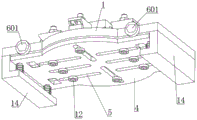
Fig. 1 is a schematic view I of the overall structure of the present invention;
fig. 2 is a schematic view II of the overall structure of the present invention;
fig. 3 is a schematic view of the overall structure of the present invention;
fig. 4 is an exploded view of the drive assembly, the base plate and the lifter plate of the present invention;
FIG. 5 is a cross-sectional view of the screw and the swash block of the present invention;
fig. 6 is a cross-sectional view of the first waist-shaped groove, the second waist-shaped groove, the bolt and the trapezoidal block of the present invention;
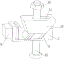
fig. 7 is a schematic structural diagram of the slider, clamping block and trapezoidal block of the present invention.
In the figure: 1. the device comprises a base plate, 2, a sliding groove, 3, a first waist-shaped groove, 4, a lifting plate, 5, a second waist-shaped groove, 6, a driving component, 601, a screw rod, 602, an inclined block, 603, an open groove, 604, a guide pillar, 605, a spring, 7, a sliding block, 8, a clamping block, 9, a chute, 10, a trapezoidal block, 11, a third waist-shaped groove, 12, a bolt, 13, a hexagon nut, 14 and a base plate.
Detailed Description
The technical solutions in the embodiments of the present invention will be described clearly and completely with reference to the accompanying drawings in the embodiments of the present invention, and it is obvious that the described embodiments are only some embodiments of the present invention, not all embodiments. Based on the embodiments in the present invention, all other embodiments obtained by a person skilled in the art without creative work belong to the protection scope of the present invention.
Referring to fig. 1-7, the present invention provides a technical solution: a rapid clamping fixture for machining a pump body of an excavator comprises a base plate 1, wherein a plurality of transverse and vertical sliding grooves 2 are formed in the upper side face of the base plate 1, a first waist-shaped groove 3 is formed in each sliding groove 2, the first waist-shaped groove 3 is formed in the middle of each sliding groove 2, the first waist-shaped groove 3 penetrates through the side wall of the base plate 1, a lifting plate 4 is connected to the lower portion of the base plate 1 in a sliding mode through a driving assembly 6, a plurality of second waist-shaped grooves 5 are formed in each lifting plate 4, the second waist-shaped grooves 5 penetrate through the side wall of the base plate 1, each second waist-shaped groove 5 corresponds to the first waist-shaped grooves 3 one by one, a sliding block 7 is connected to the inner portion of each first waist-shaped groove 3 in a sliding mode, a clamping block 8 is connected to each sliding block 7 in a horizontal direction in a sliding mode, when the pump body is placed in the middle of the base plate 1, the sliding blocks 7 are located around the pump body, therefore, the clamping blocks 8 are located around the pump body, when the pump body is pushed by the clamping blocks 8, the pump body can be clamped on the bottom plate 1, the slide block 7 is provided with a chute 9, the slide block 7 is connected with a trapezoidal block 10 in a sliding manner along the direction of the chute 9, and the inclined plane of the trapezoidal block 10 is movably connected with the clamping blocks 8, as shown in fig. 6-7, the chute 9 is gradually close to the clamping blocks 8 from top to bottom, the inner side wall of the trapezoidal block 10 is fixedly connected with a guide block, and the guide block slides in the inclined block 9, so that when the trapezoidal block 10 slides downwards, the trapezoidal block 10 slides along the direction of the chute 9 and then gradually approaches the clamping blocks 8, then the inclined plane of the trapezoidal block 10 is contacted with the clamping blocks 8 and then pushes against the clamping blocks 8 to slide, so that the clamping blocks 8 push against the pump body to fix the pump body, the side wall of the trapezoidal block 10 is provided with a third waist-shaped groove 11, the inside sliding connection of third waist type groove 11 has bolt 12, the upper end meshing of bolt 12 is connected with hexagon nut 13, just hexagon nut 13 joint is on the last lateral wall of trapezoidal piece 10, and when bolt 12 slided downwards, hexagon nut 13 is pressing the last side of trapezoidal piece 10 downwards, makes trapezoidal piece 10 slide down along sloping block 9, the lower extreme of bolt 12 runs through slider 7, first waist type groove 3 and second waist type groove 5 in proper order and the joint is on the lower lateral wall of lifter plate 4, and bolt 12 can slide along first waist type groove 3 and second waist type groove 5 to slider 7 can carry out the change of position in the inside of spout 2, then can adjust the device with holding the space wantonly, realizes the quick clamping of changing outfit between the different model pump bodies.
Specifically, backing plates 14 are fixedly connected to two ends of the bottom plate 1, the bottom plate 1 is lifted by the backing plates 14, and then a space for the driving assembly 6 to move is reserved on the lower side of the bottom plate 1.
Specifically, the driving assembly 6 includes screws 601 rotatably connected to the inside of the two ends of the bottom plate 1, the two ends of each of the two screws 601 are engaged and sleeved with an oblique block 602, the directions of the threads at the two ends of the screws 601 are opposite, and then when the screws 601 are rotated, the screws 601 drive the two oblique blocks 602 thereon to move relatively or away from each other, the oblique blocks 602 are slidably connected to the inside of the open slots 603, the open slots 603 are opened on the side wall of the lifting plate 4, the driving assembly 6 further includes a plurality of guide pillars 604 fixedly connected to the side wall of the backing plate 14, the upper ends of the guide pillars 604 penetrate through the side wall of the lifting plate 4 and are fixedly connected to the side wall of the bottom plate 1, a spring 605 is sleeved below the lifting plate 4 and located on the guide pillars 604, as shown in fig. 4, when the screws 601 rotate, and when the two oblique blocks 602 engaged with the same screw 601 respectively move toward the two ends of the screws 601, the oblique blocks 602 slide, the lifting plate 4 is urged to move downwards against the elastic force of the spring 605, and then the lifting plate 4 simultaneously pulls down all the bolts 12, whereas when the two inclined blocks 602 engaged with the same screw 601 move towards the middle of the screw 601, the inclined blocks 602 slide into the inside of the open grooves 603, and at this time, the lifting plate 4 slides upwards by the elastic force of the spring 605, and then the pulling force to all the bolts 12 is eliminated.
When the pump body is clamped, in order to prevent the sliding block 7 from sliding in the sliding groove 2, the friction coefficient between the bottom of the sliding block 7 and the bottom surface of the sliding groove 2 needs to be increased, and specifically, the lower side surface of the sliding block 7 and the bottom surface of the sliding groove 2 are provided with teeth arranged in an array form.
Specifically, the upper end of one side that clamping piece 8 and trapezoidal piece 10 contacted is equipped with the chamfer, and when trapezoidal piece 10 slided along chute 9, the inclined plane of trapezoidal piece 10 can contact with clamping piece 8, and trapezoidal piece 10 can extrude clamping piece 8 horizontal slip along the chamfer, prevents that clamping piece 8 from causing the interference to the slip of trapezoidal piece 10, has guaranteed that it is smooth and easy to promote clamping piece 8 to slide when trapezoidal piece 10 slides.
The working principle is as follows: when the rapid clamping device is used, a shell is placed in the middle of the upper side face of a bottom plate 1 (as shown in fig. 1), then sliding blocks 7 in a plurality of sliding grooves 2 respectively to enable clamping ends of a plurality of clamping blocks 8 to be in contact with the peripheral side walls of the shell respectively (at the moment, the clamping blocks 8 are contracted on the sliding blocks 7), then rotating two screws 601 to enable two inclined blocks 602 to slide out of an open groove 603 and push a lifting plate 4 to slide downwards, at the moment, the lifting plate 4 pulls all bolts 12 downwards to slide downwards, then hexagonal nuts 13 press the trapezoidal blocks 10 to enable the trapezoidal blocks 10 to slide on the sliding blocks 7 along inclined grooves 9, the inclined faces of the trapezoidal blocks 10 push the clamping blocks 8 to move towards a processed pump body and generate thrust on the pump body, and all the clamping blocks 8 generate thrust on the pump body simultaneously, so that the pump body is clamped rapidly; when the clamped pump body is disassembled, the two screw rods 601 are rotated reversely, then the inclined block 602 slides into the opening groove 603, the lifting plate 4 slides upwards through the elastic force of the spring 605, all the bolts 12 lose downward tensile force at the moment, so that the trapezoidal block 10 does not push the clamping block 8, all the clamping blocks 8 can simultaneously loosen the clamping on the pump body, then the quick disassembly of the pump body is realized, and the efficiency of clamping work is improved.
Although embodiments of the present invention have been shown and described, it will be appreciated by those skilled in the art that changes, modifications, substitutions and alterations can be made in these embodiments without departing from the principles and spirit of the invention, the scope of which is defined in the appended claims and their equivalents.
Claims (5)
1. The utility model provides an excavator pump body processing is with adding anchor clamps fast, includes bottom plate (1), its characterized in that: the clamping device is characterized in that the upper side surface of the bottom plate (1) is provided with a plurality of transverse and vertical sliding grooves (2), a first waist-shaped groove (3) is formed in each sliding groove (2), the lower side of the bottom plate (1) is connected with a lifting plate (4) in a sliding mode through a driving assembly (6), a plurality of second waist-shaped grooves (5) are formed in the lifting plate (4), each second waist-shaped groove (5) corresponds to each first waist-shaped groove (3) one by one, a sliding block (7) is connected in the first waist-shaped groove (3) in a sliding mode, a clamping block (8) is connected on the sliding block (7) in a sliding mode along the horizontal direction, a chute (9) is formed in the sliding block (7), a trapezoidal block (10) is connected on the sliding block (7) in a sliding mode along the direction of the chute (9), the inclined surface of the trapezoidal block (10) is movably connected with the clamping block (8), and a third waist-shaped groove (11) is formed in the side wall of the trapezoidal block, the inside sliding connection of third waist type groove (11) has bolt (12), the upper end meshing of bolt (12) is connected with hexagon nut (13), just hexagon nut (13) joint is on the lateral wall of going up of trapezoidal piece (10), the lower extreme of bolt (12) runs through slider (7), first waist type groove (3) and second waist type groove (5) and joint on the lower lateral wall of lifter plate (4) in proper order.
2. The quick clamping fixture for machining the pump body of the excavator according to claim 1, characterized in that: backing plates (14) are fixedly connected to two ends of the bottom plate (1).
3. The quick clamping fixture for machining the pump body of the excavator according to claim 2, characterized in that: the driving assembly (6) comprises screws (601) rotatably connected to the inner portions of two ends of the base plate (1), two ends of the two screws (601) are respectively meshed and sleeved with an inclined block (602), the inclined blocks (602) are slidably connected to the inner portions of the open grooves (603), the open grooves (603) are formed in the side walls of the lifting plate (4), the driving assembly (6) further comprises a plurality of guide pillars (604) fixedly connected to the side walls of the base plate (14), the upper ends of the guide pillars (604) penetrate through the side walls of the lifting plate (4) and are fixedly connected to the side walls of the base plate (1), and springs (605) are sleeved on the guide pillars (604) below the lifting plate (4).
4. The quick clamping fixture for machining the pump body of the excavator according to claim 1, characterized in that: the lower side surface of the sliding block (7) and the bottom surface of the sliding groove (2) are respectively provided with teeth which are arranged in an array form.
5. The quick clamping fixture for machining the pump body of the excavator according to claim 1, characterized in that: and a chamfer is arranged at the upper end of one side of the clamping block (8) in contact with the trapezoidal block (10).
Priority Applications (1)
| Application Number | Priority Date | Filing Date | Title |
|---|---|---|---|
| CN201921998088.5U CN211192976U (en) | 2019-11-19 | 2019-11-19 | Excavator pump body processing is with adding fast and holding anchor clamps |
Applications Claiming Priority (1)
| Application Number | Priority Date | Filing Date | Title |
|---|---|---|---|
| CN201921998088.5U CN211192976U (en) | 2019-11-19 | 2019-11-19 | Excavator pump body processing is with adding fast and holding anchor clamps |
Publications (1)
| Publication Number | Publication Date |
|---|---|
| CN211192976U true CN211192976U (en) | 2020-08-07 |
Family
ID=71855172
Family Applications (1)
| Application Number | Title | Priority Date | Filing Date |
|---|---|---|---|
| CN201921998088.5U Expired - Fee Related CN211192976U (en) | 2019-11-19 | 2019-11-19 | Excavator pump body processing is with adding fast and holding anchor clamps |
Country Status (1)
| Country | Link |
|---|---|
| CN (1) | CN211192976U (en) |
Cited By (2)
| Publication number | Priority date | Publication date | Assignee | Title |
|---|---|---|---|---|
| CN113510423A (en) * | 2021-04-12 | 2021-10-19 | 昆山博思达自动化设备科技有限公司 | Multi-direction tight welding mechanism that presss from both sides of single power supply |
| CN115338747A (en) * | 2022-09-13 | 2022-11-15 | 芜湖弘度智能科技有限公司 | Refrigerator handle processingequipment |
-
2019
- 2019-11-19 CN CN201921998088.5U patent/CN211192976U/en not_active Expired - Fee Related
Cited By (3)
| Publication number | Priority date | Publication date | Assignee | Title |
|---|---|---|---|---|
| CN113510423A (en) * | 2021-04-12 | 2021-10-19 | 昆山博思达自动化设备科技有限公司 | Multi-direction tight welding mechanism that presss from both sides of single power supply |
| CN115338747A (en) * | 2022-09-13 | 2022-11-15 | 芜湖弘度智能科技有限公司 | Refrigerator handle processingequipment |
| CN115338747B (en) * | 2022-09-13 | 2024-05-17 | 芜湖弘度智能科技有限公司 | Refrigerator handle processingequipment |
Similar Documents
| Publication | Publication Date | Title |
|---|---|---|
| CN211192976U (en) | Excavator pump body processing is with adding fast and holding anchor clamps | |
| CN114273944B (en) | CNC universal jig | |
| CN201172190Y (en) | Multifunction quick change double-moving jaw bench vice | |
| CN114165657A (en) | Multistage regulation and control flange connection device | |
| CN210010710U (en) | Machining clamping device | |
| CN212918731U (en) | Floating polishing structure for building aluminum template processing | |
| CN210121775U (en) | Rapid clamping fixture for milling machine machining | |
| CN214817996U (en) | Quick point-mounting tool clamp for house steel structure products | |
| CN217551597U (en) | Positioner clamp | |
| CN215942615U (en) | Solve motion vice of vice centre gripping depth of parallelism | |
| CN210499304U (en) | Fixed clamping mechanism for machining mechanical parts | |
| CN211191741U (en) | Feeding device for stamping die | |
| CN210791035U (en) | Manipulator device | |
| CN211421499U (en) | Construction convenience's building curtain connection structure | |
| CN210938921U (en) | Stamping part trimming clamp | |
| CN211305575U (en) | Workpiece pressing device | |
| CN217832857U (en) | Combined cylinder driving clamping mechanism | |
| CN221735711U (en) | Metal porcelain goods grinding device | |
| CN219212703U (en) | Precision polisher for stainless steel industrial templates | |
| CN213731256U (en) | Clamping and fixing mechanism for steel nail production equipment | |
| CN113510462B (en) | Corner pressing equipment for corner connectors of aluminum profile frame | |
| CN217413681U (en) | Hydraulic synchronous vice | |
| CN210966664U (en) | Template bending device capable of adjusting inner height of side mold | |
| CN210281433U (en) | Piston rod clamp | |
| CN220864587U (en) | Dust-proof particle clamp for plastic injection molding piece engraving and milling machine |
Legal Events
| Date | Code | Title | Description |
|---|---|---|---|
| GR01 | Patent grant | ||
| GR01 | Patent grant | ||
| CF01 | Termination of patent right due to non-payment of annual fee | ||
| CF01 | Termination of patent right due to non-payment of annual fee |
Granted publication date: 20200807 Termination date: 20211119 |