CN211183891U - New forms of energy panel mounting bracket - Google Patents
New forms of energy panel mounting bracket Download PDFInfo
- Publication number
- CN211183891U CN211183891U CN202020299465.2U CN202020299465U CN211183891U CN 211183891 U CN211183891 U CN 211183891U CN 202020299465 U CN202020299465 U CN 202020299465U CN 211183891 U CN211183891 U CN 211183891U
- Authority
- CN
- China
- Prior art keywords
- fixed
- fixing
- pull rod
- panel mounting
- driving pipe
- Prior art date
- Legal status (The legal status is an assumption and is not a legal conclusion. Google has not performed a legal analysis and makes no representation as to the accuracy of the status listed.)
- Expired - Fee Related
Links
Images

Classifications
-
- Y—GENERAL TAGGING OF NEW TECHNOLOGICAL DEVELOPMENTS; GENERAL TAGGING OF CROSS-SECTIONAL TECHNOLOGIES SPANNING OVER SEVERAL SECTIONS OF THE IPC; TECHNICAL SUBJECTS COVERED BY FORMER USPC CROSS-REFERENCE ART COLLECTIONS [XRACs] AND DIGESTS
- Y02—TECHNOLOGIES OR APPLICATIONS FOR MITIGATION OR ADAPTATION AGAINST CLIMATE CHANGE
- Y02E—REDUCTION OF GREENHOUSE GAS [GHG] EMISSIONS, RELATED TO ENERGY GENERATION, TRANSMISSION OR DISTRIBUTION
- Y02E10/00—Energy generation through renewable energy sources
- Y02E10/40—Solar thermal energy, e.g. solar towers
- Y02E10/47—Mountings or tracking
-
- Y—GENERAL TAGGING OF NEW TECHNOLOGICAL DEVELOPMENTS; GENERAL TAGGING OF CROSS-SECTIONAL TECHNOLOGIES SPANNING OVER SEVERAL SECTIONS OF THE IPC; TECHNICAL SUBJECTS COVERED BY FORMER USPC CROSS-REFERENCE ART COLLECTIONS [XRACs] AND DIGESTS
- Y02—TECHNOLOGIES OR APPLICATIONS FOR MITIGATION OR ADAPTATION AGAINST CLIMATE CHANGE
- Y02E—REDUCTION OF GREENHOUSE GAS [GHG] EMISSIONS, RELATED TO ENERGY GENERATION, TRANSMISSION OR DISTRIBUTION
- Y02E10/00—Energy generation through renewable energy sources
- Y02E10/50—Photovoltaic [PV] energy
Abstract
The utility model relates to a solar panel support technical field especially relates to a new forms of energy panel mounting bracket. The solar energy collecting device comprises a shaft sleeve and a driving pipe, wherein the shaft sleeve and the driving pipe are fixed through a first fixing pin, the driving pipe and a fixing sleeve are fixed through a second fixing pin, a connecting seat is arranged at the bottom of a swing arm, a rotating shaft of the connecting seat is connected to a pull rod, the top of a telescopic rod of an electric push rod is connected with a rotating shaft of the pull rod, when the electric push rod works, a solar panel can be driven to rotate through the pull rod, the swing arm and the driving pipe, the inclination angle of the solar panel can be freely adjusted according; the multiple groups of solar panels can be driven to be synchronously adjusted through a single electric push rod.
Description
Technical Field
The utility model relates to a solar panel support technical field especially relates to a new forms of energy panel mounting bracket.
Background
The solar photovoltaic bracket is a special bracket designed for placing, installing and fixing a solar panel in a solar photovoltaic power generation system. The general material includes aluminum alloy and stainless steel. When the existing solar support is installed, firstly, the fixed part of the support is poured on the ground, then the solar panel support is installed and adjusted, and finally the solar panel is installed, the angle of the solar panel can not be freely adjusted according to the sunlight irradiation intensity after the solar panel is installed, and the utilization rate of solar energy is low.
SUMMERY OF THE UTILITY MODEL
The utility model aims to solve the technical problem that the above-mentioned technique is not enough, provide a new energy cell panel mounting bracket, include that axle sleeve and driving tube are fixed through first fixed pin, it is fixed through the second fixed pin to drive between tube and the fixed cover, the swing arm bottom is provided with the connecting seat, the connecting seat pivot is connected on the pull rod, electric putter's telescopic link top and pull rod pivot are connected, can drive solar panel through pull rod, swing arm and driving tube and rotate when electric putter work, can freely adjust solar panel's inclination according to solar illumination intensity, and the utilization ratio of solar energy improves greatly; the multiple groups of solar panels can be driven to be synchronously adjusted through a single electric push rod.
In order to solve the technical problem, the utility model discloses the technical scheme who adopts is: comprises a base, a main beam, a nut, a driving pipe, a swing arm, a pull rod and a support frame; the base is poured on the ground; the top of the base is provided with a fixing bolt; the bottom of the main beam is provided with a fixed disc; the fixed disc is fixedly arranged on the base; a plurality of solar panels are fixedly arranged on one side of the supporting frame, and a plurality of fixing plates are fixedly arranged on the other side of the supporting frame.
Further optimizing the technical scheme, the top of the main beam is provided with a first fixed seat; a second fixed seat is arranged at the top of the first fixed seat; a bearing is arranged between the first fixed seat and the second fixed seat; the driving pipe penetrates through the middle of the bearing.
Further optimizing the technical scheme, the fixing plate is provided with a shaft sleeve; the driving pipe penetrates through the middle part of the shaft sleeve; the shaft sleeve and the driving pipe are provided with first fixing holes; a first fixing pin is arranged at the position of the first fixing hole; the shaft sleeve and the driving pipe are fixed through a first fixing pin.
Further optimizing the technical scheme, the driving pipes on the left supporting frame and the right supporting frame are coaxial; a fixed sleeve is arranged at the top of the swing arm; the fixed sleeve is sleeved on the two driving pipes which are adjacent left and right.
Further optimizing the technical scheme, the two ends of the driving pipe and the fixing sleeve are provided with second fixing holes; a second fixing pin is arranged on the second fixing hole; the driving pipe and the fixed sleeve are fixed through a second fixing pin.
Further optimizing the technical scheme, the pull rod is arranged below the swing arm; the bottom of the swing arm is provided with a connecting seat; the connecting seat rotating shaft is connected to the pull rod.
Further optimizing the technical scheme, a control console is poured on the ground below the middle part of the pull rod; and the console is fixedly provided with a mounting seat.
An electric push rod is connected to the upper rotating shaft of the mounting seat; the top of the telescopic rod of the electric push rod is connected with the pull rod rotating shaft.
Compared with the prior art, the utility model has the advantages of it is following:
1. when the electric push rod works, the solar panel can be driven to rotate by the pull rod, the swing arm and the driving pipe, and the inclination angle of the solar panel can be freely adjusted according to the solar illumination intensity.
2. The driving pipes on the left supporting frame and the right supporting frame are coaxial; a fixed sleeve is arranged at the top of the swing arm; the fixed sleeve is sleeved on the left and right adjacent driving pipes, and the driving pipes can be spliced through the independent fixed sleeve to freely arrange and combine the solar panels.
3. Can realize driving multiunit solar panel synchronous regulation through single electric putter.
4. Whole device design need not artifical guard and can realize solar panel freedom angle regulation to absorb conversion solar energy with the highest efficiency, solar panel generating efficiency is higher.
Drawings
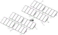
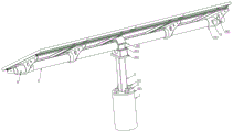
Fig. 1 is a front perspective structure diagram of a new energy battery panel mounting rack.
Fig. 2 is a back three-dimensional structure diagram of a new energy battery panel mounting rack.
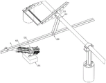
Fig. 3 is a partial exploded view of a structure of a mounting part of a driving pipe and a support frame of a new energy battery panel mounting frame.
Fig. 4 is a partial enlarged view of a mounting structure of a pull rod, a swing arm and an electric push rod of a new energy battery panel mounting frame.
In the figure: 1. a base; 101. fixing the bolt; 2. a main beam; 201. fixing the disc; 202. a first fixed seat; 203. a second fixed seat; 204. a bearing; 3. a nut; 4. a drive tube; 5. swinging arms; 501. fixing a sleeve; 502. a connecting seat; 6. a pull rod; 601. a console; 602. a mounting seat; 603. an electric push rod; 7. a support frame; 701. a solar panel; 702. a fixing plate; 703. a shaft sleeve; 8. a first fixing hole; 801. a first fixing pin; 9. a second fixing hole; 901. a second fixing pin.
Detailed Description
In order to make the objects, technical solutions and advantages of the present invention more apparent, the present invention will be described in detail with reference to the accompanying drawings. It should be understood that the description is intended to be illustrative only and is not intended to limit the scope of the present invention. Moreover, in the following description, descriptions of well-known structures and techniques are omitted so as to not unnecessarily obscure the concepts of the present invention.
The first embodiment is as follows: combine shown in fig. 1-4, its characterized in that of a new forms of energy panel mounting bracket: the device comprises a base 1, a main beam 2, a nut 3, a driving pipe 4, a swing arm 5, a pull rod 6 and a support frame 7; the base 1 is poured on the ground; the top of the base 1 is provided with a fixing bolt 101; the bottom of the main beam 2 is provided with a fixed disc 201; the fixed disc 201 is fixedly arranged on the base 1; a plurality of solar panels 701 are fixedly arranged on one side of the support frame 7, and a plurality of fixing plates 702 are fixedly arranged on the other side of the support frame.
Preferably, a first fixing seat 202 is arranged at the top of the main beam 2; the top of the first fixed seat 202 is provided with a second fixed seat 203; a bearing 204 is arranged between the first fixed seat 202 and the second fixed seat 203; the driving pipe 4 is installed through the middle of the bearing 204.
Preferably, a shaft sleeve 703 is arranged on the fixing plate 702; the driving pipe 4 penetrates through the middle part of the shaft sleeve 703; the shaft sleeve 703 and the driving pipe 4 are both provided with a first fixing hole 8; a first fixing pin 801 is installed at the position of the first fixing hole 8; the bushing 703 and the drive tube 4 are fixed by a first fixing pin 801.
Preferably, the driving pipes 4 on the left support frame 7 and the right support frame 7 are coaxial; the top of the swing arm 5 is provided with a fixed sleeve 501; the fixed sleeve 501 is sleeved on the two adjacent driving pipes 4.
Preferably, the two ends of the driving pipe 4 and the fixing sleeve 501 are both provided with a second fixing hole 9; a second fixing pin 901 is mounted on the second fixing hole 9; the driving tube 4 and the fixing sleeve 501 are fixed by a second fixing pin 901.
Preferably, the pull rod 6 is arranged below the swing arm 5; the bottom of the swing arm 5 is provided with a connecting seat 502; the connecting base 502 is connected to the pull rod 6.
Preferably, a control console 601 is poured on the ground below the middle part of the pull rod 6; the console 601 is fixedly provided with a mounting seat 602.
Preferably, an electric push rod 603 is connected to an upper shaft of the mounting seat 602; the top of the telescopic rod of the electric push rod 603 is connected with the rotating shaft of the pull rod 6.
When in use, step one, shown in the combined drawings of fig. 1-4, during installation, corresponding cement platforms, namely a base 1 and a console 601, are poured on the ground; the base 1 is poured on the ground; the top of the base 1 is provided with a fixing bolt 101; the bottom of the main beam 2 is provided with a fixed disc 201; the fixed disk 201 is fixedly arranged on the base 1, the fixed disk 201 at the bottom of the main beam 2 is fixed on the base 1, then the bearing 204 is placed on the first fixed seat 202 at the top of the main beam 2, then the second fixed seat 203 is installed, and the bearing 204 is fixed between the first fixed seat 202 and the second fixed seat 203 through the second fixed seat 203.
The supporting frame 7 is lifted, and then the driving tube 4 is penetrated from one end, so that the driving tube 4 penetrates through the shaft sleeve 703 and the bearing 204, and the shaft sleeve 703 and the driving tube 4 are both provided with a first fixing hole 8; a first fixing pin 801 is installed at the position of the first fixing hole 8; the shaft sleeve 703 and the driving tube 4 are fixed by a first fixing pin 801', the driving tube 4 and the support frame 7 are fixed by the first fixing pin 801, and the support frame 7 is driven to rotate together when the driving tube 4 rotates; and finishing the installation of the single solar energy group.
Then other groups of solar brackets are arranged, so that the driving pipes 4 of the transverse solar groups are concentrically arranged.
Step two, as shown in the combined drawings of fig. 1-4, the driving pipes 4 on the left and right supporting frames 7 are coaxial; the top of the swing arm 5 is provided with a fixed sleeve 501; the fixed sleeve 501 is sleeved on the two adjacent driving pipes 4 on the left and right, the fixed sleeve 501 is arranged between the two adjacent driving pipes 4 on the left and right, the two driving pipes 4 are fixed together through the fixed sleeve 501, and the swing arm 5 can drive the left and right driving pipes 4 to rotate together when rotating.
Then, a pull rod 6 is installed, wherein the pull rod 6 is arranged below the swing arm 5; the bottom of the swing arm 5 is provided with a connecting seat 502; the connecting seat 502 is connected to the pull rod 6 through a rotating shaft, and the swing arms 5 are sequentially connected to the pull rod 6 through rotating shafts, so that the pull rod 6 can drive the multiple groups of swing arms 5 to rotate together during movement, and the multiple groups of solar panels 701 are driven to rotate.
Finally, an electric push rod 603 is arranged on the operating platform, and the electric push rod 603 is connected to the upper shaft of the mounting seat 602; the top of the telescopic rod of the electric push rod 603 is connected with the rotating shaft of the pull rod 6, so that the pull rod 6 is pushed to move when the electric push rod 603, and the multiple groups of solar panels 701 can be driven to be synchronously adjusted through the single electric push rod 603.
In conclusion, when the electric push rod 603 works, the solar panel 701 can be driven to rotate by the pull rod 6, the swing arm 5 and the driving tube 4, the inclination angle of the solar panel 701 can be freely adjusted according to the solar illumination intensity, and the utilization rate of solar energy is greatly improved.
The utility model discloses a control mode comes automatic control through the controller, and the control circuit of controller can realize through the simple programming of technical staff in this field, belongs to the common general knowledge in this field, and the utility model discloses mainly be used for protecting mechanical device, so the utility model discloses no longer explain control mode and circuit connection in detail.
It is to be understood that the above-described embodiments of the present invention are merely illustrative of or explaining the principles of the invention and are not to be construed as limiting the invention. Therefore, any modification, equivalent replacement, improvement and the like made without departing from the spirit and scope of the present invention should be included in the protection scope of the present invention. Further, it is intended that the appended claims cover all such variations and modifications as fall within the scope and boundaries of the appended claims or the equivalents of such scope and boundaries.
Claims (8)
1. The utility model provides a new forms of energy panel mounting bracket which characterized in that: comprises a base (1), a main beam (2), a nut (3), a driving pipe (4), a swing arm (5), a pull rod (6) and a support frame (7); the base (1) is poured on the ground; the top of the base (1) is provided with a fixing bolt (101); a fixed disc (201) is arranged at the bottom of the main beam (2); the fixed disc (201) is fixedly arranged on the base (1); a plurality of solar panels (701) are fixedly arranged on one side of the supporting frame (7), and a plurality of fixing plates (702) are fixedly arranged on the other side of the supporting frame.
2. The new energy panel mounting rack of claim 1, wherein: a first fixed seat (202) is arranged at the top of the main beam (2); a second fixed seat (203) is arranged at the top of the first fixed seat (202); a bearing (204) is arranged between the first fixed seat (202) and the second fixed seat (203); the driving pipe (4) is arranged in the middle of the bearing (204) in a penetrating way.
3. The new energy panel mounting rack of claim 1, wherein: a shaft sleeve (703) is arranged on the fixing plate (702); the driving pipe (4) penetrates through the middle part of the shaft sleeve (703); the shaft sleeve (703) and the driving pipe (4) are both provided with a first fixing hole (8); a first fixing pin (801) is installed at the position of the first fixing hole (8); the shaft sleeve (703) and the driving pipe (4) are fixed through a first fixing pin (801).
4. The new energy panel mounting rack of claim 1, wherein: the driving pipes (4) on the left and right supporting frames (7) are coaxial; the top of the swing arm (5) is provided with a fixed sleeve (501); the fixed sleeve (501) is sleeved on the two driving pipes (4) which are adjacent left and right.
5. The new energy panel mounting rack of claim 4, wherein: the two ends of the driving pipe (4) and the fixed sleeve (501) are provided with second fixed holes (9); a second fixing pin (901) is arranged on the second fixing hole (9); the driving pipe (4) and the fixing sleeve (501) are fixed through a second fixing pin (901).
6. The new energy panel mounting rack of claim 1, wherein: the pull rod (6) is arranged below the swing arm (5); the bottom of the swing arm (5) is provided with a connecting seat (502); the connecting seat (502) is connected with the pull rod (6) through a rotating shaft.
7. The new energy panel mounting rack of claim 1, wherein: a control console (601) is poured on the ground below the middle part of the pull rod (6); and a mounting seat (602) is fixedly arranged on the console (601).
8. The new energy panel mounting rack of claim 7, wherein: an electric push rod (603) is connected to the upper rotating shaft of the mounting seat (602); the top of the telescopic rod of the electric push rod (603) is connected with the rotating shaft of the pull rod (6).
Priority Applications (1)
| Application Number | Priority Date | Filing Date | Title |
|---|---|---|---|
| CN202020299465.2U CN211183891U (en) | 2020-03-12 | 2020-03-12 | New forms of energy panel mounting bracket |
Applications Claiming Priority (1)
| Application Number | Priority Date | Filing Date | Title |
|---|---|---|---|
| CN202020299465.2U CN211183891U (en) | 2020-03-12 | 2020-03-12 | New forms of energy panel mounting bracket |
Publications (1)
| Publication Number | Publication Date |
|---|---|
| CN211183891U true CN211183891U (en) | 2020-08-04 |
Family
ID=71805737
Family Applications (1)
| Application Number | Title | Priority Date | Filing Date |
|---|---|---|---|
| CN202020299465.2U Expired - Fee Related CN211183891U (en) | 2020-03-12 | 2020-03-12 | New forms of energy panel mounting bracket |
Country Status (1)
| Country | Link |
|---|---|
| CN (1) | CN211183891U (en) |
Cited By (2)
| Publication number | Priority date | Publication date | Assignee | Title |
|---|---|---|---|---|
| CN114319946A (en) * | 2022-01-10 | 2022-04-12 | 雅生活明日环境发展有限公司 | Multifunctional biological ecological public toilet |
| CN115694061A (en) * | 2022-12-28 | 2023-02-03 | 东莞市特姆优传动科技有限公司 | But solar panel electric putter of split combination |
-
2020
- 2020-03-12 CN CN202020299465.2U patent/CN211183891U/en not_active Expired - Fee Related
Cited By (3)
| Publication number | Priority date | Publication date | Assignee | Title |
|---|---|---|---|---|
| CN114319946A (en) * | 2022-01-10 | 2022-04-12 | 雅生活明日环境发展有限公司 | Multifunctional biological ecological public toilet |
| CN114319946B (en) * | 2022-01-10 | 2024-04-16 | 雅生活明日环境发展有限公司 | Multifunctional biological ecological public toilet |
| CN115694061A (en) * | 2022-12-28 | 2023-02-03 | 东莞市特姆优传动科技有限公司 | But solar panel electric putter of split combination |
Similar Documents
| Publication | Publication Date | Title |
|---|---|---|
| WO2010069115A1 (en) | Automatic sun-tracking photovoltaic electrical energy generation device | |
| CN211183891U (en) | New forms of energy panel mounting bracket | |
| CN205566190U (en) | Solar cell panel's angle adjusting device | |
| CN217282837U (en) | Adjustable installing support of photovoltaic board convenient to dismouting | |
| CN216672919U (en) | Adjustable photovoltaic cell board | |
| CN216518387U (en) | Wind, light and storage integrated power generation device | |
| CN114024492A (en) | Photovoltaic panel lighting angle automatic regulating system | |
| CN210197756U (en) | Heat collector of angle-adjustable flat plate type solar water heater | |
| CN209419556U (en) | A kind of photovoltaic bracket improving photovoltaic panel generated energy | |
| CN217423654U (en) | Stable self-generating solar support who prevents wind | |
| CN220190760U (en) | Adjustable integrated photovoltaic device | |
| CN220234566U (en) | Wind-photovoltaic-resistant power generation support with adjusting mechanism | |
| CN213365336U (en) | Linkage type solar photovoltaic panel | |
| CN218806413U (en) | Surface of water photovoltaic module support, surface of water photovoltaic system and surface of water photovoltaic power plant | |
| CN216516351U (en) | Adjustable energy-saving building photovoltaic curtain wall | |
| CN215520227U (en) | Bipv bicycle shed photovoltaic support system with wind-resistant structure | |
| CN220775715U (en) | Photovoltaic panel installing support | |
| CN218387383U (en) | Distributed photovoltaic power generation and energy storage device | |
| CN218276560U (en) | Self-adjusting photovoltaic support | |
| CN201351580Y (en) | Wind power generation device of four-tower and double-fan blade portal type wind wheel | |
| CN220586197U (en) | Balance weight stable photovoltaic bracket | |
| CN216056887U (en) | Device of adjustable photovoltaic board angle | |
| CN217680848U (en) | Photovoltaic bicycle shed | |
| CN219458964U (en) | Photovoltaic support and photovoltaic power generation device | |
| CN219960471U (en) | Large-span flexible photovoltaic bracket |
Legal Events
| Date | Code | Title | Description |
|---|---|---|---|
| GR01 | Patent grant | ||
| GR01 | Patent grant | ||
| CF01 | Termination of patent right due to non-payment of annual fee |
Granted publication date: 20200804 Termination date: 20210312 |
|
| CF01 | Termination of patent right due to non-payment of annual fee |