CN211182743U - Electric socket with good safety - Google Patents
Electric socket with good safety Download PDFInfo
- Publication number
- CN211182743U CN211182743U CN201921965865.6U CN201921965865U CN211182743U CN 211182743 U CN211182743 U CN 211182743U CN 201921965865 U CN201921965865 U CN 201921965865U CN 211182743 U CN211182743 U CN 211182743U
- Authority
- CN
- China
- Prior art keywords
- socket
- end surface
- board
- socket board
- groove
- Prior art date
- Legal status (The legal status is an assumption and is not a legal conclusion. Google has not performed a legal analysis and makes no representation as to the accuracy of the status listed.)
- Active
Links
Images


Landscapes
- Connector Housings Or Holding Contact Members (AREA)
Abstract
An electric socket with good safety belongs to the technical field of socket design, and particularly relates to an electric socket with good safety. The upper end of socket head is equipped with the switch, the left end surface of socket head is equipped with the connector lug, the inboard of connector lug is equipped with the sealing washer, the right-hand member bottom of socket head is equipped with the socket board, the front end surface of socket board is equipped with two recesses, the rear end surface correspondence of every recess is equipped with a set of two hole plugs, the upper end surface of socket board is equipped with two bosss, the surface correspondence of every boss is equipped with a set of three hole plugs, the right side correspondence of every three hole plugs of group is equipped with a power indicator, the upper end of socket board is equipped with the shield, the left end of shield is connected with the socket head through the connecting. After the technical scheme is adopted, the utility model discloses beneficial effect does: the dustproof cover is arranged above the socket board and can prevent dust, the side wall of the socket board is provided with a groove, the groove is matched with the wiring plug and is not easy to loosen, and stability and safety are improved.
Description
Technical Field
The utility model relates to a socket technical field, concretely relates to electric socket that security is good.
Background
The socket is also called as a power socket and a switch socket. A socket is a receptacle into which one or more circuit connections can be inserted, through which various connections can be inserted. Therefore, the connection with other circuits is convenient, and the connection and disconnection of the part of the circuit are finally achieved through the connection and disconnection between the circuit and the copper piece.
The electric socket on the existing market is that power plug exposes outside more, does not have safeguard measure, accumulates the dust easily on the socket surface, and the connection of wiring plug and electric socket is unstable moreover, and is easy not hard up, has the danger of electrocuteeing when serious.
Disclosure of Invention
An object of the utility model is to prior art's defect and not enough, provide an electric socket that security is good, it installs the shield in the top of socket, can prevent dust, is equipped with the recess at the lateral wall of socket, and the recess is identical with the wiring plug, and is difficult not hard up, improves stability and security.
In order to achieve the above purpose, the utility model adopts the following technical scheme: it contains the socket head, a switch, the connector lug, the sealing washer, the socket board, a groove, two hole plugs, the boss, three hole plugs, power indicator, the shield, the connecting axle, the upper end of socket head is equipped with the switch, the left end surface of socket head is equipped with the connector lug, the inboard of connector lug is equipped with the sealing washer, the right-hand member bottom of socket head is equipped with the socket board, the front end surface of socket board is equipped with two recesses, the rear end surface correspondence of every recess is equipped with a set of two hole plugs, the upper end surface of socket board is equipped with two bosss, the surface correspondence of every boss is equipped with a set of three hole plugs, the right side correspondence of every three hole plugs of group is equipped with a power indicator, the upper end of socket board is equipped with the shield, the left end of.
Further, each groove and each boss correspond to each other.
Furthermore, the groove is a square groove. The recess is square groove, also can be various shapes such as circular, square, oval, and the user can select corresponding groove shape according to the shape of wiring plug, lets the wiring plug can inlay in the recess, improves the stability of wiring plug connection.
When the socket board is used, a user holds the protruding block with one hand to open the dustproof cover upwards, and then covers the dustproof cover after the wiring plug is inserted into the three-hole plug, so that the surface of the socket board is kept clean and tidy.
Furthermore, the bottom of the right end of the dustproof cover is provided with a protruding block, and the protruding block is integrally connected with the dustproof cover.
The utility model has the working principle that the device is connected according to the position, a power line is inserted from a connector lug and connected with a socket head, a switch is arranged on the upper end surface of the socket head, the switch is pressed to connect a circuit, and then the switch is pressed to disconnect the circuit, the right end of the socket head is connected with a socket board, two grooves are arranged on the front end surface of the socket board, a two-hole plug is correspondingly arranged on the rear end surface of each groove, the bottom surface of the connector plug is matched with the grooves, so that the connection is more stable and not easy to loose, two bosses are arranged on the upper end surface of the socket board, the end surfaces of the bosses are higher than the end surfaces of the socket board, so that dust on the upper surface of the socket board cannot be gathered at a three-hole plug when the dust falls into the upper surface of the socket board, the safety of electric appliance connection is improved, a dustproof cover is arranged above the socket board and is in a shape of L, the dustproof cover is made of transparent plastic, so that the waterproof, the dustproof cover is arranged when the socket board is not used, one hand of a user can hold the cover upwards, the wiring head is inserted, and the dustproof cover is inserted cleanly and the three-hole cover.
After the technical scheme is adopted, the utility model discloses beneficial effect does: the dustproof cover is arranged above the socket board and can prevent dust, the side wall of the socket board is provided with a groove, the groove is matched with the wiring plug and is not easy to loosen, and stability and safety are improved.
Drawings
In order to more clearly illustrate the embodiments of the present invention or the technical solutions in the prior art, the drawings needed to be used in the description of the embodiments or the prior art will be briefly described below, it is obvious that the drawings in the following description are only some embodiments of the present invention, and for those skilled in the art, other drawings can be obtained according to these drawings without inventive exercise.
Fig. 1 is a schematic structural diagram of the present invention;
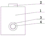
FIG. 2 is a left side view corresponding to FIG. 1;
fig. 3 is a top view corresponding to fig. 1.
Description of reference numerals: socket head 1, switch 2, connector lug 3, sealing washer 4, socket 5, recess 6, two hole plugs 7, boss 8, three hole plugs 9, power indicator 10, shield 11, connecting axle 12, bulge 13.
Detailed Description
Referring to fig. 1 to fig. 3, the technical solution adopted by the present embodiment is: the socket comprises a socket head 1, a switch 2, a connector lug 3, a sealing ring 4, a socket board 5, a groove 6, a two-hole plug 7, a boss 8, a three-hole plug 9, a power indicator lamp 10, a dust cover 11 and a connecting shaft 12, wherein the switch 2 is arranged at the upper end of the socket head 1, the connector lug 3 is arranged on the left end surface of the socket head 1, the sealing ring 4 is arranged on the inner side of the connector lug 3, the socket board 5 is arranged at the bottom of the right end of the socket head 1, the two grooves 6 are arranged on the front end surface of the socket board 5, a group of two-hole plugs 7 are correspondingly arranged on the rear end surface of each groove 6, two bosses 8 are arranged on the upper end surface of the socket board 5, a group of three-hole plugs 9 are correspondingly arranged on the surface of each boss 8, a power indicator lamp 10 is correspondingly arranged on the right side of each group of plugs 9, the dust cover, the right end of the dust cover 11 contacts the right end face of the socket board 5.
Each groove 6 and each boss 8 correspond to each other.
The groove 6 is a square groove. The groove 6 is a square groove and can also be in various shapes such as a circle, a square and an ellipse, and a user can select the corresponding groove shape according to the shape of the wiring plug, so that the wiring plug can be embedded in the groove 6, and the connection stability of the wiring plug is improved.
The dustproof cover 11 is an L-shaped dustproof cover, the dustproof cover 11 is a L-shaped dustproof cover, the dustproof cover 11 is made of transparent plastics and has waterproof, electricity-proof and dustproof effects, when the socket board 5 is not used, the dustproof cover 11 is covered, when the socket board is required to be used, a user holds the protruding block 13 with one hand to open the dustproof cover 11 upwards, and after the wiring plug is inserted into the three-hole plug 9, the dustproof cover 11 is covered, so that the surface of the socket board 5 is kept clean and tidy.
The bottom of the right end of the dust cover 11 is provided with a protruding block 13, and the protruding block 13 is integrally connected with the dust cover 11.
The utility model discloses a theory of operation is that the device is connected according to the position, the power cord inserts from the connector lug 3 and is connected with socket 1, be equipped with switch 2 on the upper end surface of socket 1, press switch 2 and put through the circuit, press the switch again and then be the open circuit, the right-hand member of socket 1 is connected with socket 5, the front end surface of socket 5 is equipped with two recesses 6, the rear end surface of recess 6 corresponds and is equipped with a two hole plug 7, let the bottom surface of wiring plug coincide with recess 6, so connect more stably, difficult not hard up, be equipped with two bosss 8 on the upper end surface of socket 5, the terminal surface of boss 8 is higher than the terminal surface of socket 5, when the dust falls into the upper surface of socket 5, the dust on the upper surface of socket 5 can not assemble in three hole plugs 9, improve the security of electrical apparatus connection, be equipped with shield 11 above socket 5, shield 11 is "L" shape shield, shield 11 is made of transparent plastics, have waterproof, prevent electric shock and dust and when not using socket 5, clean cover 11, need make a neat cover, make the plug 11, insert the wiring plug, hold between the three hole plug, again, hold between the three hole plug, hold between the plug, hold the three hole plug is covered.
After the technical scheme is adopted, the utility model discloses beneficial effect does: the dustproof cover is arranged above the socket board and can prevent dust, the side wall of the socket board is provided with a groove, the groove is matched with the wiring plug and is not easy to loosen, and stability and safety are improved.
The above description is only for the purpose of illustrating the technical solutions of the present invention and not for the purpose of limiting the same, and other modifications or equivalent replacements made by those of ordinary skill in the art to the technical solutions of the present invention should be covered within the scope of the claims of the present invention as long as they do not depart from the spirit and scope of the technical solutions of the present invention.
Claims (5)
1. An electric socket that security is good, its characterized in that: the novel socket comprises a socket head (1), a switch (2), a connector lug (3), a sealing ring (4), a socket board (5), grooves (6), two-hole plugs (7), bosses (8), three-hole plugs (9), power indicator lamps (10), a dust cover (11) and a connecting shaft (12), wherein the switch (2) is arranged at the upper end of the socket head (1), the connector lug (3) is arranged on the left end surface of the socket head (1), the sealing ring (4) is arranged on the inner side of the connector lug (3), the socket board (5) is arranged at the bottom of the right end of the socket head (1), the two grooves (6) are arranged on the front end surface of the socket board (5), a group of two-hole plugs (7) are correspondingly arranged on the rear end surface of each groove (6), the two bosses (8) are arranged on the upper end surface of the socket board (5), a group of three-hole plugs (9) are correspondingly arranged on the surface of each boss (8), and one power, the upper end of the socket board (5) is provided with a dustproof cover (11), and the left end of the dustproof cover (11) is connected with the socket head (1) through a connecting shaft (12).
2. An electrical receptacle according to claim 1, wherein: each groove (6) and each boss (8) correspond to each other.
3. An electrical receptacle according to claim 1, wherein: the groove (6) is a square groove.
4. An electrical socket according to claim 1, wherein said dust cover (11) is in the form of "L".
5. An electrical receptacle according to claim 1, wherein: the dustproof cover is characterized in that a protruding block (13) is arranged at the bottom of the right end of the dustproof cover (11), and the protruding block (13) is integrally connected with the dustproof cover (11).
Priority Applications (1)
| Application Number | Priority Date | Filing Date | Title |
|---|---|---|---|
| CN201921965865.6U CN211182743U (en) | 2019-11-14 | 2019-11-14 | Electric socket with good safety |
Applications Claiming Priority (1)
| Application Number | Priority Date | Filing Date | Title |
|---|---|---|---|
| CN201921965865.6U CN211182743U (en) | 2019-11-14 | 2019-11-14 | Electric socket with good safety |
Publications (1)
| Publication Number | Publication Date |
|---|---|
| CN211182743U true CN211182743U (en) | 2020-08-04 |
Family
ID=71805447
Family Applications (1)
| Application Number | Title | Priority Date | Filing Date |
|---|---|---|---|
| CN201921965865.6U Active CN211182743U (en) | 2019-11-14 | 2019-11-14 | Electric socket with good safety |
Country Status (1)
| Country | Link |
|---|---|
| CN (1) | CN211182743U (en) |
-
2019
- 2019-11-14 CN CN201921965865.6U patent/CN211182743U/en active Active
Similar Documents
| Publication | Publication Date | Title |
|---|---|---|
| CN202423666U (en) | Waterproof electric connector and water boiling pot with same | |
| CN211182743U (en) | Electric socket with good safety | |
| CN210838235U (en) | Multifunctional folding USB patch board | |
| CN103700976A (en) | Socket | |
| CN202423690U (en) | Rotary type safe disconnecting power expansion board with water-draining structure | |
| CN211182623U (en) | Wiring socket with outer cover | |
| CN208127520U (en) | A kind of electrical appliance connecting wire convenient for plug-pull waterproof | |
| CN210443976U (en) | Wire storage box | |
| CN208478703U (en) | A kind of individual event two-stage on-off plug with dust-proof protective structure | |
| CN203760715U (en) | Convertible plug power device | |
| CN203119208U (en) | Electric connector | |
| CN209045950U (en) | A kind of more USB intelligent sockets of the positive anti-plug of waterproof | |
| CN218216018U (en) | Power track control adapter | |
| CN205016753U (en) | Many -Modular socket | |
| CN213401663U (en) | Multi-jack intelligent socket convenient to high in safety in use | |
| CN213989373U (en) | Novel socket waterproof cover | |
| CN221226691U (en) | Travel socket with foldable plug | |
| CN217485887U (en) | Intelligent storage type lightning protection USB charging socket | |
| CN204376101U (en) | A kind of novel anti-shock solidus socket | |
| CN213460276U (en) | Waterproof straight plug | |
| KR200447633Y1 (en) | Plug | |
| CN207743503U (en) | A kind of conversion socket | |
| CN212968237U (en) | Multifunctional three-plug support for power plug wire | |
| CN202737256U (en) | Plug having leakage protection function | |
| CN204391343U (en) | A kind of wall type supply socket distinguishing socket |
Legal Events
| Date | Code | Title | Description |
|---|---|---|---|
| GR01 | Patent grant | ||
| GR01 | Patent grant |