CN211175839U - Special tee joint for water purifier waste water drainage - Google Patents
Special tee joint for water purifier waste water drainage Download PDFInfo
- Publication number
- CN211175839U CN211175839U CN201922348076.4U CN201922348076U CN211175839U CN 211175839 U CN211175839 U CN 211175839U CN 201922348076 U CN201922348076 U CN 201922348076U CN 211175839 U CN211175839 U CN 211175839U
- Authority
- CN
- China
- Prior art keywords
- transmission shaft
- fixed plate
- main part
- water purifier
- waste water
- Prior art date
- Legal status (The legal status is an assumption and is not a legal conclusion. Google has not performed a legal analysis and makes no representation as to the accuracy of the status listed.)
- Active
Links
Images


Landscapes
- Water Treatment By Sorption (AREA)
Abstract
The utility model discloses a special tee bend of water purifier waste water drainage, including connecting the main part, it is discoid to connect the main part, and the upper end that connects the main part is equipped with main connection interface, main connection interface's both sides all are equipped with vice connection interface, it is equipped with transmission shaft and fixed plate to connect the main part inboard, and is equipped with the connecting rod on the transmission shaft, the connecting rod sets up with the transmission shaft is perpendicular, and one side of connecting rod is equipped with the blade, the fixed plate also sets up for perpendicular with the transmission shaft, the one end of fixed plate with connect main part fixed connection, and the other end of fixed plate passes through the bearing and is connected with the transmission shaft rotation, the middle part of fixed plate is equipped with the. Compare with traditional water purifier waste water drainage special tee bend, the utility model discloses a set up a blade in connecting the main part, need not to open this device through the blade and just can clear up its inside rubbish that blocks up, it is more convenient.
Description
Technical Field
The utility model relates to a three-way pipe technical field specifically is a special tee bend of water purifier waste water drainage.
Background
Most of the water purifiers are installed on the lower side of a kitchen sink, and tap water firstly passes through the water purifier when flowing to a faucet, and then flows out of the faucet after being filtered by the water purifier. Since many water purifiers discharge sewage, and the number of drain pipes in a kitchen is mostly fixed, a pipe joint is installed at the upper end of the drain pipe to expand. The most common problem of the existing water purifier three-way pipe is that the three-way pipe is blocked, and after the three-way pipe is blocked, the three-way pipe needs to be disassembled and then cleaned, so that the three-way pipe is very inconvenient.
Therefore, a tee special for discharging the wastewater of the water purifier is provided to solve the problems.
SUMMERY OF THE UTILITY MODEL
An object of the utility model is to provide a special tee bend of water purifier waste water drainage to solve the problem that proposes among the above-mentioned background art.
In order to achieve the above object, the utility model provides a following technical scheme: the utility model provides a special tee bend of water purifier waste water drainage, includes and connects the main part, it is discoid to connect the main part, and the upper end that connects the main part is equipped with main connection interface, main connection interface's both sides all are equipped with vice connection interface, it is equipped with transmission shaft and fixed plate to connect the main part inboard, and is equipped with the connecting rod on the transmission shaft, the connecting rod sets up with the transmission shaft is perpendicular, and one side of connecting rod is equipped with the blade, the fixed plate also sets up with the transmission shaft is perpendicular, the one end of fixed plate with connect main part fixed connection, and the other end of fixed plate passes through the bearing and is connected with the transmission shaft rotation, the middle part of.
Preferably, the transmission shaft is perpendicular to the joint main body, and the transmission shaft is rotatably connected with the joint main body through a bearing.
Preferably, the outer side of the joint main body is provided with a handle, and the handle is fixed at the end of the transmission shaft through a screw.
Preferably, the upper end of the joint main body is provided with a hollow part, and the hollow part is provided with a visible window.
Preferably, the end parts of the main connecting interface and the auxiliary connecting interface are respectively provided with a plurality of limiting convex ribs.
Compared with the prior art, the beneficial effects of the utility model are that: the utility model discloses a set up one and connect the main part, connect the main part and be discoid, be equipped with one in the inboard that connects the main part and can rotate the transmission shaft, its handle through connecting the main part outside drives the motion, is equipped with the blade on the transmission shaft, and still is equipped with a fixed plate that uses with the blade cooperation in connecting the main part, is equipped with the notch on the fixed plate, and at blade pivoted in-process, the blade can be through the notch, can cut off the filth that connects the inside jam of main part through the blade at this in-process. Compare with traditional water purifier waste water drainage special tee bend, the utility model discloses a set up a blade in connecting the main part, need not to open this device through the blade and just can clear up its inside rubbish that blocks up, it is more convenient.
Drawings
Fig. 1 is a schematic view of the internal structure of the present invention;
FIG. 2 is a front view of the present invention;
fig. 3 is a sectional view of the fixing plate of the present invention.
In the figure: 1. a connector body; 2. a main connection interface; 3. a secondary connection interface; 4. a drive shaft; 5. a fixing plate; 6. a connecting rod; 7. a blade; 8. a notch; 9. a handle; 10. a visible window; 11. and limiting convex ribs.
Detailed Description
The technical solutions in the embodiments of the present invention will be described clearly and completely with reference to the accompanying drawings in the embodiments of the present invention, and it is obvious that the described embodiments are only some embodiments of the present invention, not all embodiments. Based on the embodiments in the present invention, all other embodiments obtained by a person skilled in the art without creative work belong to the protection scope of the present invention.
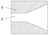
Referring to fig. 1-3, the utility model provides a tee joint special for water purifier wastewater drainage, comprising a joint main body 1, wherein the joint main body 1 is disc-shaped, the upper end of the joint main body 1 is provided with a main connecting interface 2, two sides of the main connecting interface 2 are both provided with auxiliary connecting interfaces 3, the inner side of the joint main body 1 is provided with a transmission shaft 4 and a fixed plate 5, the transmission shaft 4 is provided with a connecting rod 6, the connecting rod 6 is perpendicular to the transmission shaft 4, one side of the connecting rod 6 is provided with a blade 7, the fixed plate 5 is perpendicular to the transmission shaft 4, one end of the fixed plate 5 is fixedly connected with the joint main body 1, the other end of the fixed plate 5 is rotatably connected with the transmission shaft 4 through a bearing, the middle part of the fixed plate 5 is provided with a notch 8, one side of the notch 8 is provided with a horn-shaped, the garbage can be pushed to the fixing plate 5 by the blade 7, the fixing plate 5 can support garbage, the blade 7 can work conveniently, and the garbage can be cut off after the blade 7 goes out of the notch 8.
The transmission shaft 4 is perpendicular to the joint main body 1, and the transmission shaft 4 is rotatably connected with the joint main body 1 through a bearing. The outer side of the joint main body 1 is provided with a handle 9, and the handle 9 is fixed at the end part of the transmission shaft 4 through a screw. The transmission shaft 4 can be driven to rotate together by rotating the handle 9. The upper end of the joint main body 1 is provided with a hollow part, the hollow part is provided with a visual window 10, and the interior of the joint main body 1 can be observed through the visual window 10. The tip of main connection interface 2 and vice connection interface 3 all is equipped with the spacing protruding muscle 11 of a plurality of, and spacing protruding muscle 11 is favorable to fixing the water pipe.
In order to better understand the utility model by those skilled in the art, the working process of the utility model is briefly described with reference to the attached drawings: connect main part 1 to be discoid, be equipped with one in the inboard that connects main part 1 and can rotate transmission shaft 4, it drives the motion through the handle 9 that connects the main part 1 outside, be equipped with blade 7 on transmission shaft 4, and still be equipped with one in the joint main part 1 and cooperate the fixed plate 5 that uses with blade 7, be equipped with notch 8 on the fixed plate 5, at blade 7 pivoted in-process, blade 7 can pass through notch 8, can cut off the filth that connects the inside jam of main part 1 through blade 7 at this in-process.
Although embodiments of the present invention have been shown and described, it will be appreciated by those skilled in the art that changes, modifications, substitutions and alterations can be made in these embodiments without departing from the principles and spirit of the invention, the scope of which is defined in the appended claims and their equivalents.
Claims (5)
1. The utility model provides a special tee bend of water purifier waste water drainage, includes joint main part (1), its characterized in that: connect main part (1) to be discoid, and the upper end that connects main part (1) is equipped with main connection interface (2), the both sides of main connection interface (2) all are equipped with vice connection interface (3), connect main part (1) inboard to be equipped with transmission shaft (4) and fixed plate (5), and be equipped with connecting rod (6) on transmission shaft (4), connecting rod (6) set up with transmission shaft (4) are perpendicular, and one side of connecting rod (6) is equipped with blade (7), fixed plate (5) also set up for perpendicular with transmission shaft (4), the one end and the joint main part (1) fixed connection of fixed plate (5), and the other end of fixed plate (5) passes through the bearing and is connected with transmission shaft (4) rotation, the middle part of fixed plate (5) is equipped with notch (8), and one side of notch (8) is equipped with loudspeaker form import.
2. The tee joint special for water purifier waste water drainage according to claim 1, characterized in that: the transmission shaft (4) is perpendicular to the joint main body (1), and the transmission shaft (4) is rotatably connected with the joint main body (1) through a bearing.
3. The tee joint special for water purifier waste water drainage according to claim 1, characterized in that: the outer side of the joint main body (1) is provided with a handle (9), and the handle (9) is fixed at the end part of the transmission shaft (4) through a screw.
4. The tee joint special for water purifier waste water drainage according to claim 1, characterized in that: the upper end of the joint main body (1) is provided with a hollow part, and a visible window (10) is arranged at the hollow part.
5. The tee joint special for water purifier waste water drainage according to claim 1, characterized in that: the end parts of the main connecting interface (2) and the auxiliary connecting interface (3) are respectively provided with a plurality of limiting convex ribs (11).
Priority Applications (1)
| Application Number | Priority Date | Filing Date | Title |
|---|---|---|---|
| CN201922348076.4U CN211175839U (en) | 2019-12-24 | 2019-12-24 | Special tee joint for water purifier waste water drainage |
Applications Claiming Priority (1)
| Application Number | Priority Date | Filing Date | Title |
|---|---|---|---|
| CN201922348076.4U CN211175839U (en) | 2019-12-24 | 2019-12-24 | Special tee joint for water purifier waste water drainage |
Publications (1)
| Publication Number | Publication Date |
|---|---|
| CN211175839U true CN211175839U (en) | 2020-08-04 |
Family
ID=71827303
Family Applications (1)
| Application Number | Title | Priority Date | Filing Date |
|---|---|---|---|
| CN201922348076.4U Active CN211175839U (en) | 2019-12-24 | 2019-12-24 | Special tee joint for water purifier waste water drainage |
Country Status (1)
| Country | Link |
|---|---|
| CN (1) | CN211175839U (en) |
-
2019
- 2019-12-24 CN CN201922348076.4U patent/CN211175839U/en active Active
Similar Documents
| Publication | Publication Date | Title |
|---|---|---|
| CN201519513U (en) | Full-automatic urban domestic sewage waterpower catch basin | |
| CN211175839U (en) | Special tee joint for water purifier waste water drainage | |
| CN201024483Y (en) | Plugging-proof device for vegetable-washing tank | |
| CN203701249U (en) | Water supply and drainage sewage pipeline convenient to dredge | |
| CN110822198A (en) | Special tee joint for water purifier waste water drainage | |
| CN201099887Y (en) | Secondary water collecting, draining device | |
| CN201843190U (en) | Sewer pipeline | |
| CN216259475U (en) | Municipal building drainage pipe road junction filter equipment | |
| CN209760414U (en) | Sewage pipes for building water supply and drainage | |
| CN214004226U (en) | Automatic waste water treatment device of clearance mud | |
| CN213268291U (en) | Sewage pipeline waste residue cleaning device | |
| CN207672685U (en) | A kind of sewer refuse disposal installation | |
| CN210216642U (en) | Detachable road infiltration pipe of sponge city filter screen | |
| CN209066546U (en) | A kind of Drinking fountain Waster water reuse apparatus | |
| CN208996186U (en) | A kind of urban sewage pipeline being collected by filtration with mud | |
| CN214763900U (en) | Wastewater collection device of wastewater treatment system | |
| CN215290430U (en) | Multifunctional elbow pipe connecting piece for food waste disposer | |
| CN216304855U (en) | Water-saving environment-friendly building water supply and drainage device | |
| CN210583973U (en) | Building engineering water supply and drainage filter equipment | |
| CN220930553U (en) | Pipeline joint integrated seat body of water purification equipment | |
| CN216640803U (en) | Drainage device of municipal water conservancy | |
| CN209752337U (en) | Environment-friendly engineering wastewater treatment device | |
| CN217325650U (en) | Anti-blocking device for building water supply and drainage | |
| CN211659367U (en) | Domestic sewage treatment equipment with layered filtering structure | |
| CN202755445U (en) | Sewage pipeline connecting pipe |
Legal Events
| Date | Code | Title | Description |
|---|---|---|---|
| GR01 | Patent grant | ||
| GR01 | Patent grant |