CN211164960U - Calender compression roller structure provided with distance adjusting mechanism and used for packaging film production - Google Patents
Calender compression roller structure provided with distance adjusting mechanism and used for packaging film production Download PDFInfo
- Publication number
- CN211164960U CN211164960U CN201922027655.9U CN201922027655U CN211164960U CN 211164960 U CN211164960 U CN 211164960U CN 201922027655 U CN201922027655 U CN 201922027655U CN 211164960 U CN211164960 U CN 211164960U
- Authority
- CN
- China
- Prior art keywords
- shell
- shaft
- driving
- compression roller
- packaging film
- Prior art date
- Legal status (The legal status is an assumption and is not a legal conclusion. Google has not performed a legal analysis and makes no representation as to the accuracy of the status listed.)
- Active
Links
Images


Landscapes
- Casting Or Compression Moulding Of Plastics Or The Like (AREA)
Abstract
The utility model discloses a be provided with roll adjustment mechanism's calender compression roller structure is used in packaging film production, including shell and compression roller body, the compression roller body sets up between the shell, the left side of shell is provided with the drive plate, and the drive plate passes through the drive shaft and rotates the connection on the shell, the right-hand member and the second motor of first cross axle are connected, and the second motor is installed on the mounting panel to the mounting panel passes through spout and shell sliding connection, all install the drive wheel on first cross axle and the second cross axle, and the drive wheel is connected through drive belt and intermediate wheel. This be provided with calender compression roller structure is used in packaging film production of roll adjustment mechanism can utilize the motor to drive rotatory mode and drive roll adjustment mechanism automatic operation, consequently only need use prior art to the rotation of motor control can to around the roll adjustment, transmission structure between the roller can self-adaptation adjustment, and it is more convenient to use.
Description
Technical Field
The utility model relates to a packaging film production facility technical field specifically is a calender compression roller structure is used in packaging film production that is provided with roll adjustment mechanism.
Background
Packaging film itself is mostly the plastics material, after the calender roll-in, makes the inhomogeneous gelatineous raw materials of thickness take place the physical form and changes, the membranous structure of transform appointed thickness to make things convenient for subsequent processing operation, the core structure in the calender is the compression roller structure, utilizes two incorgruous pivoted compression rollers to carry out the roll-in to plastics raw materials and carries the operation, but current compression roller structure has following problem when in-service use:
1. the distance between the compression rollers needs to be adjusted along with the change of processing requirements, but most of the existing adjusting modes are that the roller shafts and the shell are disassembled and connected, the distance adjusting purpose is realized by disassembling and reassembling the roller shafts and the rollers, the operation is very troublesome, and the adjusting precision is inconvenient to control;
2. before and after adjustment, because the rotating speeds of the two rollers are required to be consistent and the rotating directions must be opposite, after the distance is adjusted, the transmission structure between the two rollers needs to be manually adjusted again, and the distance adjusting efficiency is low.
Disclosure of Invention
The utility model aims to provide a calender compression roller structure provided with a distance adjusting mechanism for producing packaging films, which aims to solve the problem that the distance between compression rollers is required to be adjusted along with the change of processing requirements in the background art, but most of the existing adjusting modes are roller shaft and shell disassembly connection, the distance adjusting purpose is realized by disassembling and reassembling the roller shaft and the roller, the operation is very troublesome, and the adjusting precision is inconvenient to control; before and after adjustment, because the rotating speed requirement of two rollers is unanimous and the turning must be opposite, the transmission structure between two rollers needs manual adjustment again after the adjustment interval to current structure, the problem that roll adjustment efficiency is lower.
In order to achieve the above object, the utility model provides a following technical scheme: the utility model provides a be provided with roll adjustment mechanism's calender compression roller structure for packaging film production, includes shell and compression roller body, the compression roller body sets up between the shell, and the compression roller body is provided with two to 2 compression roller bodies are installed respectively on first cross axle and second cross axle, the left side of shell is provided with the drive plate, and the drive plate rotates through the drive shaft and connects on the shell to the drive shaft is connected through the output of belt pulley mechanism and first motor, and first motor is installed on the shell simultaneously, the right-hand member and the second motor of first cross axle are connected, and the second motor is installed on the mounting panel to the mounting panel passes through spout and shell sliding connection, all install the drive wheel on first cross axle and the second cross axle, and the drive wheel is connected through drive belt and intermediate wheel.
Preferably, the two ends of the first transverse shaft and the second transverse shaft are both rotatably connected with square blocks, and the square blocks are vertically and slidably connected inside the grooves.
Preferably, the fluting is seted up and is all distributed on the shell of both sides, and the grooved inside is provided with first spring to the both ends of first spring respectively with square piece and grooved end fixed connection.
Preferably, 1 horizontal pole is all installed at the both ends of drive plate surface, and 2 horizontal poles are connected with first cross axle and second cross axle through 1 actuating lever respectively to the actuating lever is connected with first cross axle, second cross axle and horizontal pole are the rotation, and 2 actuating levers are parallel arrangement each other simultaneously.
Preferably, the transmission belt is distributed in an irregular 8 shape, one side of the transmission belt bypasses the side surface of the intermediate wheel, and the intermediate wheel is rotatably connected to the sliding block through the rotating shaft.
Preferably, the sliding block is slidably connected in a block groove which is horizontally distributed, the end heads of the sliding block and the block groove are connected through a second spring, and the block groove is formed in the surface of the shell on the left side.
Compared with the prior art, the beneficial effects of the utility model are that: the calender compression roller structure provided with the distance adjusting mechanism for producing the packaging film can drive the distance adjusting mechanism to automatically operate in a mode of driving rotation by the motor, so that the rotation of the motor is controlled only by using the prior art, and the transmission structure between the rollers can be adjusted in a self-adaptive manner before and after distance adjustment, so that the use is more convenient;
1. the transverse shafts and the square blocks are used in a structure, so that the distance between the transverse shafts can be adjusted in a sliding mode of the square blocks while the transverse shafts and the compression roller body are ensured to rotate normally, and the structural design is more reasonable;
2. the driving plate is structurally designed, and can be driven by the operation of the first motor, so that the rotation of the driving plate is converted into power for synchronously and reversely moving the transverse shaft through the movement of the driving rod, and the distance adjustment is more convenient;
3. the state position design of drive belt and intermediate wheel when guaranteeing two cross axles and normal antiport of compression roller body, utilizes the automatic slip of intermediate wheel and pivot, realizes connection structure's between the roller automatic adjustment, and efficiency is higher.
Drawings
FIG. 1 is a schematic front view of the present invention;
FIG. 2 is a schematic diagram of the left side view of the driving plate of the present invention;
FIG. 3 is a schematic side view of the first cross shaft of the present invention;
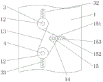
fig. 4 is a schematic view of the structure on the right side of the driving wheel of the present invention.
In the figure: 1. a housing; 2. a compression roller body; 3. a first lateral axis; 31. a square block; 32. grooving; 33. a first spring; 4. a second lateral axis; 5. a drive plate; 51. a cross bar; 52. a drive rod; 6. a drive shaft; 7. a belt pulley mechanism; 8. a first motor; 9. a second motor; 10. mounting a plate; 11. a chute; 12. a driving wheel; 13. a transmission belt; 14. an intermediate wheel; 15. a rotating shaft; 151. a slider; 152. a block groove; 153. a second spring.
Detailed Description
The technical solutions in the embodiments of the present invention will be described clearly and completely with reference to the accompanying drawings in the embodiments of the present invention, and it is obvious that the described embodiments are only some embodiments of the present invention, not all embodiments. Based on the embodiments in the present invention, all other embodiments obtained by a person skilled in the art without creative work belong to the protection scope of the present invention.
Referring to fig. 1-4, the present invention provides a technical solution: a calender compression roller structure provided with a distance adjusting mechanism and used for producing packaging films comprises a shell 1, a compression roller body 2, a first transverse shaft 3, a square block 31, a slot 32, a first spring 33, a second transverse shaft 4, a driving plate 5, a transverse rod 51, a driving rod 52, a driving shaft 6, a belt pulley mechanism 7, a first motor 8, a second motor 9, a mounting plate 10, a chute 11, a driving wheel 12, a driving belt 13, an intermediate wheel 14, a rotating shaft 15, a sliding block 151, a block groove 152 and a second spring 153, wherein the compression roller body 2 is arranged between the shell 1, the compression roller body 2 is provided with two, 2 compression roller bodies 2 are respectively arranged on the first transverse shaft 3 and the second transverse shaft 4, the driving plate 5 is arranged on the left side of the shell 1, the driving plate 5 is rotatably connected to the shell 1 through the driving shaft 6, and the driving shaft 6 is connected with the output end of the first motor, meanwhile, a first motor 8 is arranged on the shell 1, the right end of the first transverse shaft 3 is connected with a second motor 9, the second motor 9 is arranged on a mounting plate 10, the mounting plate 10 is connected with the shell 1 in a sliding mode through a sliding groove 11, driving wheels 12 are arranged on the first transverse shaft 3 and the second transverse shaft 4 respectively, and the driving wheels 12 are connected with an intermediate wheel 14 through a driving belt 13.
The two ends of the first cross shaft 3 and the second cross shaft 4 are both rotatably connected with square blocks 31, the square blocks 31 are vertically connected inside the slots 32 in a sliding manner, the slots 32 are distributed on the shell 1 on the two sides, a first spring 33 is arranged inside the slots 32, the two ends of the first spring 33 are respectively fixedly connected with the end heads of the square blocks 31 and the slots 32, when the distance between the first cross shaft 3 and the second cross shaft 4 changes, the square blocks 31 in the figure 3 can be driven to synchronously slide in the slots 32, the first spring 33 can also synchronously stretch or compress, and the first spring 33 is used for keeping the stability of the square blocks 31 and the corresponding cross shafts in daily use states.
Both ends of the outer surface of the driving plate 5 are respectively provided with 1 cross rod 51, and 2 cross rods 51 are respectively connected with the first cross shaft 3 and the second cross shaft 4 through 1 driving rod 52, and the driving rod 52 is rotatably connected with the first cross shaft 3, the second cross shaft 4 and the cross rods 51, and meanwhile, the 2 driving rods 52 are arranged in parallel, when the distance adjustment operation between the pressing roller bodies 2 is needed, firstly, the first motor 8 in fig. 2 can be operated, the driving shaft 6 is driven to synchronously rotate through the belt pulley mechanism 7, therefore, the driving plate 5 can synchronously rotate, at the moment, the cross rods 51 at both ends can drive the two driving rods 52 to move up and down at the same time of rotation, and therefore, the distance between the first cross shaft 3 and the second cross shaft 4 can correspondingly change.
The transmission belt 13 is distributed in an irregular 8 shape, one side of the transmission belt 13 bypasses the side surface of the intermediate wheel 14, the intermediate wheel 14 is rotatably connected to the sliding block 151 through the rotating shaft 15, the first transverse shaft 3 is driven to correspondingly rotate by the electrifying operation of the second motor 9, and the second transverse shaft 4 is synchronously rotated and turns opposite to the first transverse shaft 3 under the driving of the transmission belt 13 distributed in an 8 shape in fig. 4, so that the two press roll bodies 2 in fig. 1 synchronously and oppositely rotate, and the normal rolling operation is ensured.
The sliding block 151 is slidably connected in the block groove 152 which is horizontally distributed, the ends of the sliding block 151 and the block groove 152 are connected through the second spring 153, the block groove 152 is formed in the surface of the shell 1 on the left side, after the distance between the two transverse shafts is adjusted, the distance between the two transmission wheels 12 can be changed correspondingly, when the distance between the two transmission wheels 12 is increased, the transmission belt 13 can pull the intermediate wheel 14 to move towards the direction close to the transmission wheels 12, the rotating shaft 15 can drive the sliding block 151 to synchronously slide in the block groove 152, and when the distance between the two transmission wheels 12 is reduced, the rebound effect of the second spring 153 can pull the sliding block 151 and the rotating shaft 15 to move towards the right (as shown in the reference direction in fig. 4), so that the intermediate wheel.
The working principle is as follows: when the distance adjustment operation between the compression roller bodies 2 needs to be performed, firstly, the first motor 8 in fig. 2 can be operated, the driving shaft 6 is driven to synchronously rotate through the belt pulley mechanism 7, so that the driving plates 5 can synchronously rotate, and the cross rods 51 at the two ends of the driving plates can drive the two driving rods 52 to move up and down while rotating, so that the distance between the first transverse shaft 3 and the second transverse shaft 4 can correspondingly change, the square blocks 31 in fig. 3 are driven to synchronously slide in the slots 32, the first springs 33 can also synchronously stretch or compress, after the adjustment is finished, the first motor 8 can be stopped to operate, and the first springs 33 are used for keeping the stability of the square blocks 31 and the corresponding transverse shafts in daily use;
the second motor 9 is powered to operate the first horizontal shaft 3 correspondingly, and under the driving of the driving belt 13 distributed in the shape of "8" in fig. 4, the second horizontal shaft 4 rotates synchronously and turns in the opposite direction to the first horizontal shaft 3, so that the two press roll bodies 2 in fig. 1 rotate synchronously and in opposite directions, and ensure the normal operation of the rolling operation, after the distance between the two horizontal shafts is adjusted, the distance between the two driving wheels 12 changes correspondingly, when the distance between the two driving wheels 12 increases, the driving belt 13 pulls the intermediate wheel 14 to move towards the driving wheels 12, the rotating shaft 15 drives the sliding block 151 to slide synchronously in the block groove 152, when the distance between the two driving wheels 12 decreases, the rebound effect of the second spring 153 pulls the sliding block 151 and the rotating shaft 15 to move to the right (as shown in the reference direction in fig. 4), so that the intermediate wheel 14 moves away from the driving wheels 12, the belt 13 is ensured to be in a tight state, and the normal transmission between the first cross shaft 3 and the second cross shaft 4 is ensured.
Although embodiments of the present invention have been shown and described, it will be appreciated by those skilled in the art that changes, modifications, substitutions and alterations can be made in these embodiments without departing from the principles and spirit of the invention, the scope of which is defined in the appended claims and their equivalents.
Claims (6)
1. The utility model provides a be provided with roll adjustment mechanism's calender roll structure for packaging film production, includes shell (1) and compression roller body (2), its characterized in that: the compression roller comprises a shell (1), two compression roller bodies (2) are arranged between the shell (1), the 2 compression roller bodies (2) are respectively arranged on a first transverse shaft (3) and a second transverse shaft (4), a driving plate (5) is arranged on the left side of the shell (1), the driving plate (5) is rotatably connected onto the shell (1) through a driving shaft (6), the driving shaft (6) is connected with the output end of a first motor (8) through a belt pulley mechanism (7), the first motor (8) is arranged on the shell (1), the right end of the first transverse shaft (3) is connected with a second motor (9), the second motor (9) is arranged on a mounting plate (10), the mounting plate (10) is slidably connected with the shell (1) through a sliding groove (11), and transmission wheels (12) are arranged on the first transverse shaft (3) and the second transverse shaft (4), and the driving wheel (12) is connected with the intermediate wheel (14) through a driving belt (13).
2. The calender roll structure provided with the distance adjusting mechanism for producing the packaging film according to claim 1, wherein: the two ends of the first transverse shaft (3) and the second transverse shaft (4) are both rotatably connected with square blocks (31), and the square blocks (31) are vertically and slidably connected inside the grooves (32).
3. The calender roll structure provided with the distance adjusting mechanism for producing the packaging film, according to claim 2, is characterized in that: fluting (32) are seted up and are all distributed on shell (1) of both sides, and the inside of fluting (32) is provided with first spring (33) to the both ends of first spring (33) respectively with square piece (31) and fluting (32) end department fixed connection.
4. The calender roll structure provided with the distance adjusting mechanism for producing the packaging film according to claim 1, wherein: the two ends of the outer surface of the driving plate (5) are respectively provided with 1 cross rod (51), and 2 cross rods (51) are respectively connected with a first cross shaft (3) and a second cross shaft (4) through 1 driving rod (52), the driving rods (52) are rotatably connected with the first cross shaft (3), the second cross shaft (4) and the cross rods (51), and meanwhile, the 2 driving rods (52) are arranged in parallel.
5. The calender roll structure provided with the distance adjusting mechanism for producing the packaging film according to claim 1, wherein: the transmission belt (13) is distributed in an irregular 8 shape, one side of the transmission belt (13) bypasses the side surface of the middle wheel (14), and the middle wheel (14) is rotatably connected to the sliding block (151) through a rotating shaft (15).
6. The calender roll structure provided with the distance adjusting mechanism for producing the packaging film, according to claim 5, is characterized in that: the sliding block (151) is connected in the block grooves (152) which are horizontally distributed in a sliding mode, the end heads of the sliding block and the block grooves are connected through a second spring (153), and the block grooves (152) are formed in the surface of the shell (1) on the left side.
Priority Applications (1)
| Application Number | Priority Date | Filing Date | Title |
|---|---|---|---|
| CN201922027655.9U CN211164960U (en) | 2019-11-22 | 2019-11-22 | Calender compression roller structure provided with distance adjusting mechanism and used for packaging film production |
Applications Claiming Priority (1)
| Application Number | Priority Date | Filing Date | Title |
|---|---|---|---|
| CN201922027655.9U CN211164960U (en) | 2019-11-22 | 2019-11-22 | Calender compression roller structure provided with distance adjusting mechanism and used for packaging film production |
Publications (1)
| Publication Number | Publication Date |
|---|---|
| CN211164960U true CN211164960U (en) | 2020-08-04 |
Family
ID=71802556
Family Applications (1)
| Application Number | Title | Priority Date | Filing Date |
|---|---|---|---|
| CN201922027655.9U Active CN211164960U (en) | 2019-11-22 | 2019-11-22 | Calender compression roller structure provided with distance adjusting mechanism and used for packaging film production |
Country Status (1)
| Country | Link |
|---|---|
| CN (1) | CN211164960U (en) |
Cited By (3)
| Publication number | Priority date | Publication date | Assignee | Title |
|---|---|---|---|---|
| CN112031294A (en) * | 2020-08-18 | 2020-12-04 | 安徽工程大学 | Electric hand-held type elastic flexible coiled material extending and laying device |
| CN112171992A (en) * | 2020-09-08 | 2021-01-05 | 谷胜 | Add rubber production of new material and use squeeze roller adjusting device |
| CN112458691A (en) * | 2020-11-26 | 2021-03-09 | 江门市新会区美力赛无纺布纤维制品有限公司 | Non-woven fabrics impressed watermark equipment |
-
2019
- 2019-11-22 CN CN201922027655.9U patent/CN211164960U/en active Active
Cited By (4)
| Publication number | Priority date | Publication date | Assignee | Title |
|---|---|---|---|---|
| CN112031294A (en) * | 2020-08-18 | 2020-12-04 | 安徽工程大学 | Electric hand-held type elastic flexible coiled material extending and laying device |
| CN112031294B (en) * | 2020-08-18 | 2021-09-10 | 安徽工程大学 | Electric hand-held type elastic flexible coiled material extending and laying device |
| CN112171992A (en) * | 2020-09-08 | 2021-01-05 | 谷胜 | Add rubber production of new material and use squeeze roller adjusting device |
| CN112458691A (en) * | 2020-11-26 | 2021-03-09 | 江门市新会区美力赛无纺布纤维制品有限公司 | Non-woven fabrics impressed watermark equipment |
Similar Documents
| Publication | Publication Date | Title |
|---|---|---|
| CN211164960U (en) | Calender compression roller structure provided with distance adjusting mechanism and used for packaging film production | |
| CN205853348U (en) | A kind of automatic rolling device produced for bidirectional stretching polypropylene film | |
| CN209140611U (en) | A kind of wiredrawing machine | |
| CN208070913U (en) | A kind of adjustable rolling device of PE plastic film thickness | |
| CN214354254U (en) | Forming device for refrigerator heat-insulation fiber cotton board | |
| CN210012396U (en) | Synthetic leather pad pasting coiling mechanism | |
| CN207293709U (en) | A kind of sheet spread structure of rewinding machine | |
| CN217319294U (en) | Quick shaping wind for pipeline production | |
| CN215666175U (en) | Drum-type material collecting device for paper processing | |
| CN204869418U (en) | Calendering mechanism of plastic film production line | |
| CN202130933U (en) | Zero-friction transmission device for cloth roller of cloth rolling machine | |
| CN216072332U (en) | Finished product rolling is leveled and automatic membrane machine of rolling up of efficient | |
| CN221515708U (en) | Eccentric rolling machine for straight plate metal inner coil | |
| CN214923036U (en) | PS panel production is with quick grinding device | |
| CN211848585U (en) | Cutting machine is used in production of RO reverse osmosis water conservancy diversion cloth | |
| CN220950433U (en) | Limiting and fixing mechanism for carrier tape machine | |
| CN217201077U (en) | Automatic winding device for garment fabric production | |
| CN218491028U (en) | Novel TPU film rolling machine | |
| CN218707664U (en) | Plastic film winding device | |
| CN210335109U (en) | Metal product looper machine device | |
| CN218984333U (en) | Polishing device for strip steel oxide skin | |
| CN221369818U (en) | Label coiling mechanism is used in label production | |
| CN212173972U (en) | Coating coiling mechanism of two segmentation displacement compression rollers | |
| CN219751356U (en) | Secondary forming preparation device for waterproof coiled material | |
| CN221459309U (en) | Film blowing machine capable of adjusting tightness of wind-up roll |
Legal Events
| Date | Code | Title | Description |
|---|---|---|---|
| GR01 | Patent grant | ||
| GR01 | Patent grant |