CN211154698U - Chair with adjustable backrest angle - Google Patents
Chair with adjustable backrest angle Download PDFInfo
- Publication number
- CN211154698U CN211154698U CN201922286569.XU CN201922286569U CN211154698U CN 211154698 U CN211154698 U CN 211154698U CN 201922286569 U CN201922286569 U CN 201922286569U CN 211154698 U CN211154698 U CN 211154698U
- Authority
- CN
- China
- Prior art keywords
- chair
- connecting rod
- base
- transition frame
- welding
- Prior art date
- Legal status (The legal status is an assumption and is not a legal conclusion. Google has not performed a legal analysis and makes no representation as to the accuracy of the status listed.)
- Expired - Fee Related
Links
Images


Landscapes
- Chairs For Special Purposes, Such As Reclining Chairs (AREA)
Abstract
The utility model relates to a chair technical field specifically is a chair of adjustable back angle, the on-line screen storage device comprises a base, the top of base is equipped with the air cushion, the welding of the top front end of base has the connecting rod, the terminal horizontal welding of connecting rod has the handrail, the top joint of connecting rod has the sheath, the welding of the lower extreme of base has spacing section of thick bamboo, and has spliced transition frame in the spacing section of thick bamboo, transition frame's top pin junction has the back, transition frame's rear end horizontal welding has the layer board, be equipped with the back of the body net on the back. This device can adjust the distance of seat back, and the purpose provides more loose region for the user, to the great messenger crowd of some sizes again, can not feel crowded, and this device compact structure moreover, the quality is lighter to have reduced the waste of resource for the production of product, is favorable to the operation simultaneously, and compact structure does not take up an area of, and is real and most crowds use.
Description
Technical Field
The utility model relates to the technical field of chairs, in particular to a chair with an adjustable backrest angle.
Background
The chair is an article which is frequently seen and used by people, is furniture for daily life, is a seat with a backrest and armrests, is widely applied to schools, hospitals, companies, garden care and the like, is divided into a plurality of types, including seats, reclining chairs, back chairs and the like, provides space for people to rest and is convenient, becomes an essential part of the daily life of people, has the main function of facilitating people to rest, and is a main standard for measuring the quality of the chair.
Most of the existing chairs are fixed, cannot be adjusted and have poor comfort. Accordingly, those skilled in the art have provided a chair with an adjustable backrest angle to solve the problems set forth in the background art as described above.
SUMMERY OF THE UTILITY MODEL
An object of the utility model is to provide a chair of adjustable back angle to solve the problem that proposes among the above-mentioned background art.
In order to achieve the above object, the utility model provides a following technical scheme: the utility model provides a chair of adjustable back angle, includes the base, the top of base is equipped with the air cushion, the welding of the top front end of base has the connecting rod, the terminal horizontal welding of connecting rod has the handrail, the top joint of connecting rod has the sheath, the welding of the lower extreme of base has spacing section of thick bamboo, and has pegged graft transition frame in the spacing section of thick bamboo, transition frame's top pin joint has the back, transition frame's rear end horizontal welding has the layer board, be equipped with the back net on the back.
As a further aspect of the present invention: the welding of the bottom front end of base has the support, the support and connecting rod are on same straight line, the lower extreme of support is connected with the stabilizer blade.
As a further aspect of the present invention: the lower end pin joint in the inside of a spacing section of thick bamboo has sector gear, one side of sector gear is connected with the extension spring, and sector gear last extension spring homonymy is equipped with the pull rod, and the pull rod runs through the bottom of a spacing section of thick bamboo.
As a further aspect of the present invention: the inside top of a spacing section of thick bamboo is equipped with the slide bar, and has cup jointed the stopper on the slide bar, the bottom of stopper is connected with the rack, the tip and the transition frame of rack are connected, the bottom and the fan-shaped gear meshing of rack.
As a further aspect of the present invention: the supporting plate is provided with a screw rod in a penetrating mode, the bottom end, located on the supporting plate, of the screw rod is meshed with a nut, and the upper end of the screw rod is meshed with a threaded sleeve.
As a further aspect of the present invention: the connecting rod is connected to the threaded sleeve through a pin, a pin connecting piece is connected to the top of the connecting rod, and the pin connecting piece is connected with the backrest.
As a further aspect of the present invention: the top of the back net and the top of the air cushion are sleeved with a back cushion.
Compared with the prior art, the beneficial effects of the utility model are that: the device can adjust the distance of the back of the chair, aims to provide a loose area for a user, can not feel crowded to people with large body sizes, directly pulls the backrest backwards during adjustment, the rack moves on the sector gear, is restrained by the slide rod and the limiting block and is prevented from shaking, the sector gear can organize the rack to return to play a locking role, the sector gear retracts by the pull rod when needing to be retracted, the rack can be directly pushed back, meanwhile, the user sits for a long time, the spine of the user can be painful, waist is soreness, the angle of the backrest can be adjusted at the moment, the screw rod is directly rotated, the screw rod is abutted or the screw sleeve is pulled to move up and down, and further, the angle conversion is realized by driving the backrest by the connecting rod, the device can be exchanged through the earlier stage operation, and a comfortable feeling can be provided for the user as much as possible, the device has the advantages that different purposes are realized in different occasions by different crowds, the practicability of the product is improved, the device is compact in structure, the quality is lighter, the waste of resources is reduced for the production of the product, the operation is facilitated, the structure is compact, the occupied space is not occupied, and the device is practical for most crowds.
Description of the drawings:
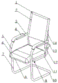
FIG. 1 is a schematic view of a chair with adjustable backrest angle;
FIG. 2 is a schematic view of a locking structure of a horizontal adjusting mechanism in a chair with adjustable backrest angle;
fig. 3 is a schematic view of an angle adjusting structure of a chair with adjustable backrest angle.
In the figure: 1. a backrest; 2. back net; 3. a handrail; 4. a sheath; 5. a connecting rod; 6. an air cushion; 7. a support; 8. a base; 9. a pull rod; 10. a support leg; 11. a limiting cylinder; 12. a transition frame; 13. a support plate; 14. a screw; 15. a limiting block; 16. a slide bar; 17. a tension spring; 18. a sector gear; 19. a rack; 20. a back pad; 21. a pin tab; 22. a connecting rod; 23. a threaded sleeve; 24. and a nut.
Detailed Description
Referring to fig. 1 to 3, in the embodiment of the present invention: the utility model provides a chair of adjustable back angle, includes base 8, the top of base 8 is equipped with air cushion 6, the welding of the top front end of base 8 has connecting rod 5, the terminal horizontal welding of connecting rod 5 has handrail 3, the top joint of connecting rod 5 has sheath 4, the welding of the lower extreme of base 8 has spacing section of thick bamboo 11, and it has transition frame 12 to peg graft in the spacing section of thick bamboo 11, the top of transition frame 12 is pinned with back 1, the rear end horizontal welding of transition frame 12 has layer board 13, be equipped with net 2 on the back 1.
In fig. 2, a support 7 is welded at the front end of the bottom of a base 8, the support 7 and a connecting rod 5 are in the same straight line, a support leg 10 is connected to the lower end of the support 7, and the support 7 and the support leg 10 form a supporting structure which can support a chair and a user.
In fig. 2, a sector gear 18 is pin-connected to the lower end inside the limiting cylinder 11, one side of the sector gear 18 is connected with a tension spring 17, a pull rod 9 is arranged on the sector gear 18 on the same side as the tension spring 17, and the pull rod 9 penetrates through the bottom of the limiting cylinder 11, when horizontal adjustment is performed, the backrest 1 is directly pulled backwards, the backrest 1 drives the transition frame 12 to move backwards, the transition frame 12 drives the rack 19 to move outwards, the rack 19 drives the sector gear 18 to rotate when moving, the sector gear 18 is restrained by the tension spring 17, the rack 19 is prevented from retracting through the sector gear 18 after adjustment is completed, when retraction is required, the sector gear 18 retracts through the pull rod 9, and the rack 19 can be directly pushed back.
In fig. 2, a slide bar 16 is arranged at the top end of the inside of the limiting barrel 11, a limiting block 15 is sleeved on the slide bar 16, a rack 19 is connected to the bottom end of the limiting block 15, the end portion of the rack 19 is connected with the transition frame 12, the bottom end of the rack 19 is meshed with the sector gear 18, the rack 19 moves on the sector gear 18, and is constrained by the slide bar 16 and the limiting block 15 to prevent shaking.
In fig. 3, a screw 14 penetrates through the supporting plate 13, a nut 24 is engaged with the screw 14 at the bottom end of the supporting plate 13, a threaded sleeve 23 is engaged with the upper end of the screw 14, the screw 14 rotates, the threaded sleeve 23 is moved up and down by utilizing the principle of thread movement, and the nut 24 prevents the screw 14 from falling off.
In fig. 3, a connecting rod 22 is pin-connected to a threaded sleeve 23, a pin connecting piece 21 is connected to the top of the connecting rod 22, the pin connecting piece 21 is connected to the backrest 1, the threaded sleeve 23 is abutted to the connecting rod 22 or pulled to change the angle of the backrest 1 when moving up and down by using the principle of thread movement, and the back cushion 20 is sleeved on the top of the back net 2 and the top of the cushion 6 together, so that the dustproof effect can be achieved.
The utility model discloses a theory of operation is: when in use, the support 7 and the support legs 10 form a supporting structure, the chair and a user can be supported, the arms of the user can be directly lapped on the sheath 4, the width of the sheath 4 is larger, which is beneficial to the blood circulation of the arms and the hands, so that the user is more comfortable, the air cushion 6 can ensure that the buttocks of the user are dry when the user sits, and the humidity is not high because of air impermeability, the device can adjust the distance of the seat backrest 1, and aims to provide a loose area for the user, for the people with large body size, the people can not feel crowded, the backrest 1 is directly pulled backwards during adjustment, the backrest 1 drives the transition frame 12 and the armrests 3 to move backwards, the bottom ends of the armrests 3 and the transition frame 12 are both provided with the limiting cylinders 11, the transition frame 12 in the limiting cylinders 11 drives the rack 19 to move outwards, and when the rack 19 moves, the sector gear 18 is driven to rotate, the sector gear 18 is restrained by the tension spring 17, the rack 19 is prevented from retracting through the sector gear 18 after adjustment is completed, the sector gear 18 retracts through the pull rod 9 when the sector gear needs to retract, the rack 19 can be directly pushed back, the end portion of the rack 19 is connected with the transition frame 12, the bottom end of the rack 19 is meshed with the sector gear 18, the rack 19 moves on the sector gear 18 and is restrained through the slide rod 16 and the limiting block 15 to prevent shaking, meanwhile, the spine of a user can be painful and waist-sore after sitting for a long time, the angle of the backrest 1 can be adjusted at the moment, the screw 14 is directly rotated, the screw 14 rotates, the screw sleeve 23 is enabled to be in lifting motion through the connecting rod 22 to abut against or pull the backrest 1 to perform angle conversion by utilizing the screw motion principle, the nut 24 prevents the screw 14 from falling off, and the back net 2 and the, back of the body net 2 and air cushion 6's top has cup jointed back of the body pad 20 jointly, can play dustproof effect, through the above-mentioned operation in earlier stage, can change this device, for the user provides more comfortable sensation as far as, do different usage in different occasions to satisfy different crowds, the practicality of product has been increased, this device compact structure moreover, the quality is lighter to the waste of the production of product reduced the resource, be favorable to the operation simultaneously, compact structure does not account for the place, real and most crowds use.
The above-mentioned, only be the concrete implementation of the preferred embodiment of the present invention, but the protection scope of the present invention is not limited thereto, and any person skilled in the art is in the technical scope of the present invention, according to the technical solution of the present invention and the utility model, the concept of which is equivalent to replace or change, should be covered within the protection scope of the present invention.
Claims (7)
1. A chair with adjustable backrest angle, comprising a base (8), characterized in that: the top of base (8) is equipped with air cushion (6), the welding of the top front end of base (8) has connecting rod (5), the terminal horizontal welding of connecting rod (5) has handrail (3), the top joint of connecting rod (5) has sheath (4), the welding of the lower extreme of base (8) has spacing section of thick bamboo (11), and has inserted transition frame (12) in spacing section of thick bamboo (11), the top pin joint of transition frame (12) has back (1), the rear end horizontal welding of transition frame (12) has layer board (13), be equipped with back of the body net (2) on back (1).
2. The chair with the adjustable backrest angle is characterized in that a bracket (7) is welded at the front end of the bottom of the base (8), the bracket (7) and the connecting rod (5) are in the same straight line, and a support leg (10) is connected to the lower end of the bracket (7).
3. The chair with the adjustable backrest angle is characterized in that a sector gear (18) is connected to the lower end of the inside of the limiting cylinder (11) in a pin mode, one side of the sector gear (18) is connected with a tension spring (17), a pull rod (9) is arranged on the same side of the upper tension spring (17) of the sector gear (18), and the pull rod (9) penetrates through the bottom of the limiting cylinder (11).
4. The chair with the adjustable backrest angle according to claim 1, characterized in that a sliding rod (16) is arranged at the top end of the inside of the limiting cylinder (11), a limiting block (15) is sleeved on the sliding rod (16), a rack (19) is connected to the bottom end of the limiting block (15), the end of the rack (19) is connected with the transition frame (12), and the bottom end of the rack (19) is meshed with the sector gear (18).
5. The chair with the adjustable backrest angle is characterized in that a screw rod (14) penetrates through the supporting plate (13), the screw rod (14) is positioned at the bottom end of the supporting plate (13) and is meshed with a nut (24), and the upper end of the screw rod (14) is meshed with a threaded sleeve (23).
6. Chair with adjustable backrest angle according to claim 5, characterized in that the screw sleeve (23) is pin-connected with a connecting rod (22), the top of the connecting rod (22) is connected with a pin sheet (21), and the pin sheet (21) is connected with the backrest (1).
7. The chair with adjustable backrest angle is characterized in that the back cushion (20) is sleeved on the top of the back net (2) and the air cushion (6) together.
Priority Applications (1)
| Application Number | Priority Date | Filing Date | Title |
|---|---|---|---|
| CN201922286569.XU CN211154698U (en) | 2019-12-19 | 2019-12-19 | Chair with adjustable backrest angle |
Applications Claiming Priority (1)
| Application Number | Priority Date | Filing Date | Title |
|---|---|---|---|
| CN201922286569.XU CN211154698U (en) | 2019-12-19 | 2019-12-19 | Chair with adjustable backrest angle |
Publications (1)
| Publication Number | Publication Date |
|---|---|
| CN211154698U true CN211154698U (en) | 2020-08-04 |
Family
ID=71814286
Family Applications (1)
| Application Number | Title | Priority Date | Filing Date |
|---|---|---|---|
| CN201922286569.XU Expired - Fee Related CN211154698U (en) | 2019-12-19 | 2019-12-19 | Chair with adjustable backrest angle |
Country Status (1)
| Country | Link |
|---|---|
| CN (1) | CN211154698U (en) |
-
2019
- 2019-12-19 CN CN201922286569.XU patent/CN211154698U/en not_active Expired - Fee Related
Similar Documents
| Publication | Publication Date | Title |
|---|---|---|
| EP4173521A1 (en) | Mechanical stretching device for movable seat unit and seat unit | |
| CN111602993A (en) | Sofa stretching device capable of providing zero-gravity sitting feeling | |
| CN201094431Y (en) | Body-building chair | |
| CN201403845Y (en) | Ergonomic leisure sitting device | |
| CN211154698U (en) | Chair with adjustable backrest angle | |
| CN106108444B (en) | Frame structure for reclining chair | |
| CN205041045U (en) | Massage chair | |
| CN201840078U (en) | Office reclining chair | |
| CN203354034U (en) | Leisure deck chair | |
| CN204599894U (en) | A kind of footrest rack mechanism of chair | |
| CN215456709U (en) | Office chair seat capable of adjusting backrest gears | |
| CN212438005U (en) | Sofa stretching device capable of providing zero-gravity sitting feeling | |
| CN201585688U (en) | Chain belt lounge chair with chair back adjustable | |
| CN2927857Y (en) | Shaft control automatic bed-chair | |
| CN202820370U (en) | Dual-purpose folded chair for lying and sitting | |
| CN111802848A (en) | Office chair capable of being automatically adjusted and used for lying and rest | |
| CN208769226U (en) | A kind of folding seat | |
| CN201452326U (en) | Folding chair | |
| CN201987065U (en) | Multifunctional bed and chair combination | |
| CN112842724A (en) | Integral type old person stands up walking auxiliary device | |
| CN2192218Y (en) | Position changed office chair | |
| CN219439751U (en) | Nursing seat for old people | |
| CN215737939U (en) | Convenient folding hidden book chair | |
| CN205597564U (en) | Chair with scalable bustle | |
| CN220966858U (en) | Chair convenient for sleeping |
Legal Events
| Date | Code | Title | Description |
|---|---|---|---|
| GR01 | Patent grant | ||
| GR01 | Patent grant | ||
| CF01 | Termination of patent right due to non-payment of annual fee | ||
| CF01 | Termination of patent right due to non-payment of annual fee |
Granted publication date: 20200804 Termination date: 20201219 |