Quick change device of power battery
Technical Field
The utility model relates to an automobile manufacturing field especially relates to a power battery's quick change device.
Background
The power battery is a core component of the new energy automobile, and in the use experience of the new energy automobile and the fuel oil automobile, particularly in the comparison of the refueling time of the fuel oil automobile, the charging time of the new energy automobile is more than half an hour, so that the rapid popularization of the new energy automobile is greatly limited, and particularly the commercial vehicle market is limited.
In the prior art, in order to solve the requirement of quickly supplementing electricity after the electric quantity of a new energy automobile is used up, automobile manufacturers and supporting manufacturers in the prior art try to quickly change packages and supplement electricity for the new energy automobile through a quick change technology, but an effective solution with strong universality and compatibility is not available at present. In addition, the existing power battery is basically connected with the vehicle body through bolts, the power battery is screwed to the vehicle body mounting bracket through equipment, and the existing power battery cannot be quickly mounted and dismounted due to the fact that the number of related mounting bolts is large and the mounting efficiency is low.
SUMMERY OF THE UTILITY MODEL
The utility model aims to solve the technical problem that a quick change device for power batteries is provided, which can realize the quick assembly and disassembly of the power batteries, improve the replacement efficiency of the power batteries and has high universality and compatibility; the structure is simple, and the cost is easy to control.
In order to solve the technical problem, an embodiment of the utility model provides a power battery's quick change device, include: can the adaptation fastening installation axle body on automobile body installing support, the top of installation axle body is equipped with the spacing subassembly of elasticity that is used for supporting to press power battery, and the bottom of installation axle body is equipped with the recess and is used for the card to hold a plurality of supporting shoe subassemblies of power battery fastening on installation axle body, and the supporting shoe subassembly includes: a support block body; the elastic piece is clamped on the supporting block body and the mounting shaft body; and run through supporting shoe body and elastic component and fasten the mounting bolt on installing the axle body, wherein: the supporting block body is extruded and is accommodated in the groove after the supporting block body uses the mounting bolt as a rotating shaft rotating angle.
The power battery mounting hole penetrates through the supporting block component, the supporting block body is opened in a rotating mode relative to the rotating shaft under the action of the elastic component, and the elastic limiting component abuts against the power battery on the supporting block body.
The supporting block body is in a plate shape and at least provided with a pressing plane and an extrusion cambered surface connected with the pressing plane; the middle part of supporting shoe body is equipped with the pilot hole that is used for supplying the construction bolt to pass.
Wherein, be equipped with the assembly groove that is used for assembling the elastic component in the pilot hole, be equipped with the spacing groove that is used for fastening the elastic component in the assembly groove.
Wherein, the spacing subassembly of elasticity includes: top locating part, cylindricality elastic component and end locating part, cylindricality elastic component and top locating part cup joint in proper order at the top of installation axle body, wherein: the top limiting part is in threaded locking with the installation shaft body, and the top limiting part is fastened on the annular limiting surface of the installation shaft body.
The top limiting piece and the bottom limiting piece are circular limiting structures with flanges respectively; the cylindrical elastic member is a cylindrical spring, and is limited between the top limiting member and the bottom limiting member.
Wherein, installation axle body is made by high strength steel or metal material, and installation axle body is the column structure that the cross-section is any one section shape in cylinder, square and the regular hexagon.
The utility model provides a power battery's quick change device has following beneficial effect: during assembly, the power battery mounting hole penetrates through the mounting shaft body to extrude the supporting block body, and the supporting block body is rotated into a groove at the bottom of the mounting shaft body; the power battery mounting hole penetrates through the supporting block assembly, the supporting block body is opened in a rotating mode relative to the rotating shaft under the action of the elastic element, and the elastic limiting assembly abuts against the power battery on the supporting block body; when the power battery is disassembled, the power battery is supported from bottom to top through the power battery tool, and the power battery tool moves synchronously; under the action of the power battery tool, the supporting block body is screwed into the groove; the power battery tool is linked with the power battery to descend synchronously, so that the power battery is separated from the battery quick-change device, the power battery can be quickly disassembled and assembled, the replacement efficiency of the power battery is improved, and the universality and the compatibility are high; the structure is simple, and the cost is easy to control.
Drawings
In order to more clearly illustrate the embodiments of the present invention or the technical solutions in the prior art, the drawings used in the description of the embodiments or the prior art will be briefly described below, it is obvious that the drawings in the following description are only some embodiments of the present invention, and for those skilled in the art, other drawings can be obtained according to these drawings without creative efforts.
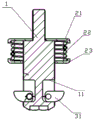
Fig. 1 is a schematic diagram of a blasting structure of a quick-change device for a power battery according to an embodiment of the present invention.
Fig. 2 is an assembly structure diagram of a quick change device for power batteries according to an embodiment of the present invention.
Fig. 3 is a schematic sectional structure view of a quick-change device for power batteries according to an embodiment of the present invention.
Fig. 4 is a schematic structural diagram of a supporting block body of a quick-change device for power batteries according to an embodiment of the present invention.
Fig. 5 is an assembly schematic diagram of the quick-change device for power battery and the power battery according to the embodiment of the present invention.
Fig. 6 is an enlarged schematic view of a quick-change device for power batteries according to an embodiment of the present invention, such as one of the quick-change devices for power batteries shown in fig. 6.
Detailed Description
The technical solutions in the embodiments of the present invention will be described clearly and completely with reference to the accompanying drawings in the embodiments of the present invention, and it is obvious that the described embodiments are only some embodiments of the present invention, not all embodiments. Based on the embodiments in the present invention, all other embodiments obtained by a person skilled in the art without creative efforts belong to the protection scope of the present invention.
Referring to fig. 1 to fig. 6, a first embodiment of the power battery quick-change device of the present invention is shown.
The quick change device of power battery in this embodiment can realize power battery's installation and dismantlement fast. As shown in fig. 5, the power battery T is assembled with the quick-change devices in this embodiment by the power battery mounting brackets T1 on both sides of the power battery T. The following description will take a quick-change device as an example to illustrate the structure of the quick-change device and how to implement quick assembly and disassembly with the mounting hole on the power battery mounting bracket T1.
As shown in fig. 1 to fig. 3, the quick-change device for power battery in this embodiment includes: can the adaptation fastening installation axle body 1 on automobile body installing support, the top of installation axle body 1 is equipped with the spacing subassembly 2 of elasticity that is used for supporting to press power battery, and the bottom of installation axle body 1 is equipped with recess 11 and is used for the card to hold a plurality of supporting shoe components 3 of power battery T fastening on installation axle body 1, and supporting shoe components 3 include: a support block body 31; an elastic member 32 held between the support block body 31 and the mounting shaft body 1; and a mounting bolt 33 penetrating the support block body 31 and the elastic member 32 and fastened to the mounting shaft body 1, wherein: the supporting block body 31 is pressed, and the supporting block body 31 is accommodated in the groove 11 after rotating for a certain angle by using the mounting bolt 33 as a rotating shaft.
The installation axle body 1 is the column structure that the cross-section is any one cross sectional shape in cylinder, square and regular hexagon, and installation axle body 1 is made by high strength steel or metal material.
The installation axle body 1 in this embodiment is cylindric, is formed by two upper and lower coaxial cylinders linking to each other, and the diameter of top cylinder is less than the diameter of bottom cylinder, and the part in succession of both forms an annular spacing face 12. The top of installation axle body 1 is equipped with the screw thread for the adaptation fastening is on automobile body installing support. The bottom of installation axle body 1 is hexagon socket or other flower type settings for twist installation axle body 1, make top screw thread can screw with automobile body installing support. In addition, the middle of the mounting shaft body 1 can be processed into various shapes capable of matching with the power battery support block assembly 3, for example, the mounting, rotation and limiting of the support block assembly 3 on the support block body 31 are facilitated.
The bottom at installation axle body 1 is evenly seted up to recess 11, and it can correspond the setting according to the number that supporting shoe subassembly 3 set up, for example: in this embodiment, the circumference of the bottom of the mounting shaft body 1 is provided with 4 grooves 11 with the same structure at equal intervals for accommodating the supporting block assembly 3.
The elastic limiting component 2 is arranged at the top of the installation shaft body 1 and is used for abutting against the power battery in the assembly of the power battery.
Spacing subassembly 2 of elasticity includes: top locating part 21, cylindricality elastic component 22 and end locating part 23, cylindricality elastic component 22 and top locating part 21 cup joint in proper order at the top of installation axle body 1, wherein: the top limit part 21 is screwed with the mounting shaft body 1, and the top limit part 21 is fastened on the annular limit surface 12 of the mounting shaft body 1.
In specific implementation, the top limiting member 21 and the bottom limiting member 23 are circular limiting structures with flanges, and are made of high-strength steel or metal. The cylindrical elastic member 22 is a cylindrical spring, the cylindrical elastic member 22 is limited between the top limiting member 21 and the bottom limiting member 23, and the flange mainly plays a limiting role.
The supporting block assembly 3 is used for clamping the power battery mounting hole through a quick clamp so that the power battery T can be fastened on the mounting shaft body 1, and therefore the power battery can be mounted and dismounted.
In specific implementation, the supporting block assembly 3 includes: a support block body 31; an elastic member 32 held between the support block body 31 and the mounting shaft body 1; and a mounting bolt 33 penetrating the support block body 31 and the elastic member 32 and fastened to the mounting shaft body 1.
Further referring to fig. 4, the supporting block body 31 is plate-shaped, and the supporting block body 31 is at least provided with a pressing plane 31a and an extrusion arc surface 31b connected with the pressing plane 31 a; the middle portion of the supporting block body 31 is provided with an assembling hole 311 for the mounting bolt 33 to pass through. Meanwhile, a fitting groove 3111 for fitting the elastic member 32 is provided in the fitting hole 311, and a stopper groove 3112 for fastening an end portion of the elastic member 32 is provided in the fitting groove 3111.
The elastic member 32 is a spring with fixing structures on both sides, and the fixing structures are inserted into the limiting groove 3112 of the supporting block body 31 and the adaptive positions in the installation shaft body 1 to realize limiting and fixing. The mounting bolts 33 are 1 high-strength bolts and cylindrical, and the mounting end faces are provided with straight grooves, cross grooves or other flower-shaped screwing structures.
Specifically, as shown in fig. 5, the elastic member 32 is placed in the assembly groove 3111 of the support block body 31, the support block body 31 and the elastic member 32 are placed in the groove 11, and the mounting bolt 33 penetrates through the assembly hole at the center of the support block body 31 and the elastic member 32 and is fastened to the mounting shaft body 1 to complete assembly. After assembly, the support block body 31 can rotate about the mounting bolt 33. The elastic member 32 causes the supporting block body 31 to be opened relative to the mounting shaft body 1, and the supporting block body 31 can rotate around the mounting bolt 33 as a rotating shaft under the action of external force (in the direction from the supporting block assembly 3 to the elastic limit assembly 2), and is accommodated in the groove 11 under the action of continuous external force. That is, the pressing arc surface 31b of the supporting block body 31 is pressed, and the supporting block body 31 can be received in the groove 11 after rotating by a certain angle using the mounting bolt 33 as a rotation axis.
When the quick-change device for the power battery in the embodiment is specifically implemented, firstly, the quick-change device assembly is screwed into the vehicle body mounting bracket through the threads at the top end of the mounting shaft body 1, and the specific screwing torque requirement is determined according to the requirement of the power battery. Power battery T passes through the frock and from up holding up down, power battery both sides mounting hole aligns the quick change device in this embodiment, continue upwards to lift by the bottom of installation axle body 1, supporting shoe body 31 uses mounting bolt 33 to inwards rotate as the pivot under the effect of power battery mounting hole, when supporting shoe subassembly 3 of installation axle body 1 bottom passes the power battery mounting hole, power battery T upwards compresses the spacing subassembly 2 of elasticity, when reacing a certain position, supporting shoe body 31 automatic re-setting to the open mode under the effect of elastic component 32, power battery T falls back to supporting shoe body 31 supports on pressing plane 31a, the spacing subassembly 2 of elasticity pushes down power battery T from top to bottom simultaneously, thereby power battery T's quick installation has been realized.
When the power battery T is disassembled, the bottom of the power battery T is supported from bottom to top through the tool, and the tool of the power battery moves synchronously; under the action of the power battery tool, the supporting block body 31 rotates by a certain angle by taking a mounting bolt 33 as a rotating shaft and then is accommodated in the groove 11 at the bottom of the mounting shaft body 1, and meanwhile, the upper elastic limiting component 2 is compressed, and when the supporting block body 31 is completely closed; the power battery tool is linked with the power battery T to descend synchronously, so that the power battery T is separated from the battery quick-change device, and quick disassembly is realized.
The utility model discloses a quick change device of power battery, quick change device can carry out the lectotype of quantity and device size according to power battery in-service use demand, is similar to the standard component. Meanwhile, the vehicle body does not need to be subjected to matching modification, the quick-change device can be directly screwed into the vehicle body to enable the vehicle body to be in a usable state, and the universality and the compatibility are high. The power battery does not need to be additionally provided with an additional device or structure, and the battery and the vehicle body can be directly fastened and connected through the quick-change device. The device has simple structure, good manufacturability and low cost, and can be widely popularized and used.
In addition, the front end design work of the power battery quick-change device only needs to be carried out, complex matching design is not needed, and the feasibility is high. The whole vehicle production process can realize quick installation. After the automobile is put into the market, the quick disassembly and assembly of the power battery can meet the battery replacement requirement of the current new energy vehicle, the battery replacement time is even quicker than that of fuel oil vehicle refueling, and the automobile product competitiveness and the popularization of the new energy vehicle can be effectively improved.
Implement the utility model discloses a power battery's quick change device has following beneficial effect: during assembly, the power battery mounting hole penetrates through the mounting shaft body to extrude the supporting block body, and the supporting block body is rotated into a groove at the bottom of the mounting shaft body; the power battery mounting hole penetrates through the supporting block assembly, the supporting block body is opened in a rotating mode relative to the rotating shaft under the action of the elastic element, and the elastic limiting assembly abuts against the power battery on the supporting block body; when the power battery is disassembled, the power battery is supported from bottom to top through the power battery tool, and the power battery tool moves synchronously; under the action of the power battery tool, the supporting block body is screwed into the groove; the power battery tool is linked with the power battery to descend synchronously, so that the power battery is separated from the battery quick-change device, the power battery can be quickly disassembled and assembled, the replacement efficiency of the power battery is improved, and the universality and the compatibility are high; the structure is simple, and the cost is easy to control.