CN211138005U - A core secondary demoulding mechanism for car speed change casing mould - Google Patents
A core secondary demoulding mechanism for car speed change casing mould Download PDFInfo
- Publication number
- CN211138005U CN211138005U CN201922068095.1U CN201922068095U CN211138005U CN 211138005 U CN211138005 U CN 211138005U CN 201922068095 U CN201922068095 U CN 201922068095U CN 211138005 U CN211138005 U CN 211138005U
- Authority
- CN
- China
- Prior art keywords
- fixedly connected
- slider
- sides
- groove
- mould
- Prior art date
- Legal status (The legal status is an assumption and is not a legal conclusion. Google has not performed a legal analysis and makes no representation as to the accuracy of the status listed.)
- Active
Links
Images


Abstract
The utility model discloses a core secondary demoulding mechanism for automobile transmission casing mould, comprising a base plate, bottom plate fixedly connected with bed die, the fluting has been seted up at the middle part of bed die upper surface, the slider has been cup jointed in the slotted inner chamber symmetrical slip, the equal fixedly connected with gag lever post in middle part of slider both sides, the draw-in groove has all been seted up to the both sides of fluting inner wall, the inner chamber and the gag lever post slip of draw-in groove cup joint, the guide slot has been seted up at the middle part of slider upper surface, the top of bed die is provided with the mould, go up the equal fixedly connected with oblique guide pillar in middle part of mould lower surface both sides, and. The utility model discloses utilize the mode of setting up of slider, two slider symmetry sliding connection are on the bed die, and the cooperation of guide slot and oblique guide pillar is used, and when making the mould separation, two slider back of the body movements of mutually backing to reach the effect of mould separation, avoid the slider of both sides to the anomalous part joint of gear shift housing appearance, and the slider dismantles the convenience.
Description
Technical Field
The utility model relates to a core secondary demoulding mechanism field of mould, in particular to a core secondary demoulding mechanism for automobile speed change casing mould.
Background
In the present injection molding product shaping production, when processing production simple structure, the product of shape rule, generally only need once drawing of patterns, can break away from injection molding's product from the mould, and when shaping product appearance structure is comparatively complicated, some product appearances especially have the buckle, like car speed change casing module, injection mold adopts the mold release technique of forcing usually, can cause the damage to the convex part of car speed change casing like this, lead to the product part to take place to warp, the cracked defect of buckle, cause the product percent of pass to be low.
SUMMERY OF THE UTILITY MODEL
An object of the utility model is to provide a core secondary demoulding mechanism for automobile transmission housing mould to solve the problem that provides among the above-mentioned background art.
In order to achieve the above object, the utility model provides a following technical scheme: the utility model provides a core secondary demoulding mechanism for automobile transmission housing mould, includes the bottom plate, the middle part fixedly connected with bed die of bottom plate upper surface, the fluting has been seted up at the middle part of bed die upper surface, the slider has been cup jointed in the slotted inner chamber symmetry slip, the equal fixedly connected with gag lever post in middle part of slider both sides, the draw-in groove has all been seted up to the both sides of fluting inner wall, the inner chamber and the gag lever post of draw-in groove slip cup joint, the guide slot has been seted up at the middle part of slider upper surface, the top of bed die is provided with the mould, the equal fixedly connected with oblique guide pillar in middle part of going up mould lower surface both sides, just the inner chamber.
Preferably, the elastic clamping blocks are symmetrically and fixedly connected to the two sides of the sliding block, the two ends of the inner wall of the groove are symmetrically provided with limiting grooves, and the inner cavities of the limiting grooves are in sliding clamping connection with the elastic clamping blocks.
Preferably, the middle part of the upper surface of the bottom plate is fixedly connected with a support frame, the top of the support frame is symmetrically provided with slide holes, the inner cavity of each slide hole is sleeved with a connecting rod in a sliding manner, and the bottom of each connecting rod is fixedly connected with the upper die.
Preferably, a through hole is formed in the middle of the upper surface of the support frame, a hydraulic cylinder is fixedly connected to an inner cavity of the through hole, and an output end of the hydraulic cylinder is in transmission connection with the middle of the upper surface of the upper die.
Preferably, a limiting hole is formed in the middle of the upper surface of the bottom plate, a connecting hole is formed in the middle of the lower surface of the lower die, an inner cavity of the connecting hole is communicated with an inner cavity of the limiting hole, a thimble is sleeved in the inner cavity of the connecting hole in a sliding mode, a limiting plate is sleeved in the inner cavity of the limiting hole in a sliding mode, the bottom of the thimble is fixedly connected with the limiting plate, and a spring is sleeved on the outer wall of the thimble in a sliding mode.
Preferably, the hydraulic cylinder is electrically connected with an external power supply through an external hydraulic cylinder switch.
The utility model discloses a technological effect and advantage:
1. the utility model utilizes the arrangement mode of the slide blocks, the two slide blocks are symmetrically and slidably connected on the lower die, and the guide groove and the inclined guide post are matched for use, so that when the die is separated, the two slide blocks move oppositely, thereby achieving the effect of separating the die, avoiding the slide blocks at the two sides from clamping the irregular part of the appearance of the speed changing shell, causing the damage of products, and being convenient for disassembling the slide blocks;
2. the utility model discloses utilize the mode that sets up of thimble, after once drawing of patterns is accomplished, the thimble carries out the secondary drawing of patterns to the product, makes the complete mould of following of product break away from, avoids the product to damage, has improved the qualification rate of variable speed casing, and has improved the production efficiency of variable speed casing.
Drawings
Fig. 1 is a schematic view of the overall structure of the present invention.
Fig. 2 is a schematic view of the side internal structure of the present invention.
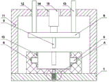
Fig. 3 is a schematic view of the front internal structure of the present invention.
Fig. 4 is an enlarged schematic view of a portion a in fig. 2 according to the present invention.
In the figure: 1. a base plate; 2. a lower die; 3. grooving; 4. a slider; 5. a limiting rod; 6. a card slot; 7. a guide groove; 8. an upper die; 9. an inclined guide post; 10. an elastic clamping block; 11. a support frame; 12. a slide hole; 13. a connecting rod; 14. a through hole; 15. a hydraulic cylinder; 16. a limiting hole; 17. connecting holes; 18. a thimble; 19. a limiting plate; 20. a spring.
Detailed Description
The technical solutions in the embodiments of the present invention will be described clearly and completely with reference to the accompanying drawings in the embodiments of the present invention, and it is obvious that the described embodiments are only some embodiments of the present invention, not all embodiments. Based on the embodiments in the present invention, all other embodiments obtained by a person skilled in the art without creative work belong to the protection scope of the present invention.
The utility model provides a core secondary demoulding mechanism for an automobile speed change shell mould as shown in figures 1-4, which comprises a bottom plate 1, a lower mould 2 is fixedly connected with the middle part of the upper surface of the bottom plate 1, a slot 3 is arranged at the middle part of the upper surface of the lower mould 2, a slide block 4 is sleeved in the inner cavity of the slot 3 in a symmetrical sliding way, the slide block 4 can be dismounted by pulling the slide block 4 towards two sides, the maintenance of the slide block 4 and the lower mould 2 is convenient, a limiting rod 5 is fixedly connected with the middle parts of two sides of the slide block 4, a slot 6 is arranged at two sides of the inner wall of the slot 3, the inner cavity of the slot 6 is sleeved with the limiting rod 5 in a sliding way, a guide groove 7 is arranged at the middle part of the upper surface of the slide block 4, an upper mould 8 is arranged at the top of the lower mould 2, an inclined guide post 9 is fixedly connected with the middle parts of two, when the inclined guide post 9 vertically falls, the inclined guide post 9 slides in the inner cavity of the guide groove 7, so that the sliding block 4 moves, the two sides of the sliding block 4 are symmetrically and fixedly connected with the elastic clamping blocks 10, when the inclined guide post 9 is separated from the guide groove 7, the elastic clamping blocks 10 are in sliding clamping connection with the limiting grooves, one position of the sliding block 4 is limited, when the inclined guide post 9 is in sliding sleeve connection with the inner cavity of the guide groove 7, the elastic clamping blocks 10 are elastically deformed and separated from the inner cavity of the limiting grooves, the two ends of the inner wall of the slot 3 are symmetrically provided with the limiting grooves, and the inner cavity of the limiting grooves is in sliding clamping connection;
a support frame 11 is fixedly connected to the middle of the upper surface of the bottom plate 1, slide holes 12 are symmetrically formed in the top of the support frame 11, a connecting rod 13 is slidably sleeved in an inner cavity of each slide hole 12, the bottom of each connecting rod 13 is fixedly connected with the upper die 8, a through hole 14 is formed in the middle of the upper surface of the support frame 11, a hydraulic cylinder 15 is fixedly connected to the inner cavity of each through hole 14, and the output end of each hydraulic cylinder 15 is in transmission connection with the middle of the upper surface of the upper die;
the middle part of the upper surface of the bottom plate 1 is provided with a limiting hole 16, the bottom of the inner cavity of the limiting hole 16 is fixedly sleeved with an air inlet pipe, so that air pressure difference is generated in the limiting hole 16, the speed change shell is separated from the die by an ejector pin 18, the middle part of the lower surface of the lower die 2 is provided with a connecting hole 17, the inner cavity of the connecting hole 17 is mutually communicated with the inner cavity of the limiting hole 16, the inner cavity of the connecting hole 17 is sleeved with the ejector pin 18 in a sliding mode, the inner cavity of the limiting hole 16 is sleeved with a limiting plate 19 in a sliding mode, the bottom of the ejector pin 18 is fixedly connected with the limiting plate 19;
the hydraulic cylinder 15 is electrically connected with an external power supply through an external hydraulic cylinder switch.
This practical theory of operation: when the mold works, firstly, a hydraulic cylinder switch is turned on, the hydraulic cylinder 15 is electrified to work, the output end of the hydraulic cylinder 15 drives the upper mold 8 to descend, at the moment, the inclined guide post 9 is in sliding sleeve joint with the guide groove 7, the upper mold 8 continues to descend, the two slide blocks 4 move oppositely under the matching use of the inclined guide post 9 and the guide groove 7 until the upper mold 8 is attached to the lower mold 2, and then the speed change shell is molded;
after the speed-changing shell is molded, a hydraulic cylinder switch is opened, a hydraulic cylinder 15 is electrified to work, the hydraulic cylinder 15 drives an upper die 8 to ascend, the two sliding blocks 4 move back to back under the matching use of the inclined guide post 9 and the guide groove 7 until the inclined guide post 9 is separated from the inner cavity of the guide groove 7, so that the die separation effect is achieved, then the elastic clamping block 10 is in sliding clamping connection with the limiting groove, then gas is guided into the limiting hole 16 from the gas inlet pipe, the limiting plate 19 moves in the inner cavity of the limiting hole 16, so that the thimble 18 pushes the speed-changing shell out of the inner cavity of the die, and secondary demolding is achieved.
Finally, it should be noted that: although the present invention has been described in detail with reference to the foregoing embodiments, it will be apparent to those skilled in the art that modifications and variations can be made in the embodiments or in part of the technical features of the embodiments without departing from the spirit and the scope of the invention.
Claims (6)
1. The utility model provides a core secondary demoulding mechanism for automotive transmission housing mould, includes bottom plate (1), its characterized in that: the middle part of the upper surface of the bottom plate (1) is fixedly connected with a lower die (2), the middle part of the upper surface of the lower die (2) is provided with a groove (3), an inner cavity of the groove (3) is symmetrically and slidably sleeved with a sliding block (4), the middle parts of two sides of the sliding block (4) are fixedly connected with limiting rods (5), two sides of the inner wall of the groove (3) are provided with clamping grooves (6), the inner cavity of each clamping groove (6) is slidably sleeved with the limiting rods (5), the middle part of the upper surface of the sliding block (4) is provided with a guide groove (7), the top of the lower die (2) is provided with an upper die (8), the middle parts of two sides of the lower surface of the upper die (8) are fixedly connected with oblique guide pillars (9), and the inner cavity of the guide groove.
2. The secondary core demolding mechanism for the automobile transmission case mold as claimed in claim 1, wherein: the two sides of the sliding block (4) are symmetrically and fixedly connected with elastic clamping blocks (10), the two ends of the inner wall of the groove (3) are symmetrically provided with limiting grooves, and inner cavities of the limiting grooves are connected with the elastic clamping blocks (10) in a sliding and clamping mode.
3. The secondary core demolding mechanism for the automobile transmission case mold as claimed in claim 1, wherein: the middle part of the upper surface of the bottom plate (1) is fixedly connected with a support frame (11), slide holes (12) are symmetrically formed in the top of the support frame (11), an inner cavity of each slide hole (12) is sleeved with a connecting rod (13) in a sliding mode, and the bottom of each connecting rod (13) is fixedly connected with the upper die (8).
4. The secondary core demolding mechanism for the automobile transmission case mold as claimed in claim 3, wherein: through-hole (14) have been seted up in the middle part of support frame (11) upper surface, the inner chamber fixedly connected with pneumatic cylinder (15) of through-hole (14), the output of pneumatic cylinder (15) is connected with the middle part transmission of upper die (8) upper surface.
5. The secondary core demolding mechanism for the automobile transmission case mold as claimed in claim 1, wherein: spacing hole (16) have been seted up at the middle part of bottom plate (1) upper surface, connecting hole (17) have been seted up at the middle part of bed die (2) lower surface, just the inner chamber of connecting hole (17) and the inner chamber of spacing hole (16) communicate each other, thimble (18) have been cup jointed in the inner chamber of connecting hole (17) slip, limiting plate (19) have been cup jointed in the inner chamber slip of spacing hole (16), the bottom and limiting plate (19) fixed connection of thimble (18), spring (20) have been cup jointed in the outer wall slip of thimble (18).
6. The secondary core demolding mechanism for the automobile transmission case mold as claimed in claim 4, wherein: the hydraulic cylinder (15) is electrically connected with an external power supply through an external hydraulic cylinder switch.
Priority Applications (1)
| Application Number | Priority Date | Filing Date | Title |
|---|---|---|---|
| CN201922068095.1U CN211138005U (en) | 2019-11-26 | 2019-11-26 | A core secondary demoulding mechanism for car speed change casing mould |
Applications Claiming Priority (1)
| Application Number | Priority Date | Filing Date | Title |
|---|---|---|---|
| CN201922068095.1U CN211138005U (en) | 2019-11-26 | 2019-11-26 | A core secondary demoulding mechanism for car speed change casing mould |
Publications (1)
| Publication Number | Publication Date |
|---|---|
| CN211138005U true CN211138005U (en) | 2020-07-31 |
Family
ID=71777486
Family Applications (1)
| Application Number | Title | Priority Date | Filing Date |
|---|---|---|---|
| CN201922068095.1U Active CN211138005U (en) | 2019-11-26 | 2019-11-26 | A core secondary demoulding mechanism for car speed change casing mould |
Country Status (1)
| Country | Link |
|---|---|
| CN (1) | CN211138005U (en) |
Cited By (1)
| Publication number | Priority date | Publication date | Assignee | Title |
|---|---|---|---|---|
| CN112895574A (en) * | 2021-01-15 | 2021-06-04 | 滁州美杰精密部件制造有限公司 | Convenient baffle forming die who dismantles |
-
2019
- 2019-11-26 CN CN201922068095.1U patent/CN211138005U/en active Active
Cited By (1)
| Publication number | Priority date | Publication date | Assignee | Title |
|---|---|---|---|---|
| CN112895574A (en) * | 2021-01-15 | 2021-06-04 | 滁州美杰精密部件制造有限公司 | Convenient baffle forming die who dismantles |
Similar Documents
| Publication | Publication Date | Title |
|---|---|---|
| CN211138005U (en) | A core secondary demoulding mechanism for car speed change casing mould | |
| CN210553225U (en) | Portable demoulding structure of hardware mould | |
| CN209832438U (en) | Electric vehicle front steering lamp reflector injection mold based on slider spring needle demolding technology | |
| CN211683286U (en) | Core pulling mechanism of injection mold | |
| CN211729939U (en) | Mould structure convenient to drawing of patterns | |
| CN219464760U (en) | Powder metallurgy injection molding six-hole triangular block product mold | |
| CN210283100U (en) | Injection mold with core-pulling mechanism | |
| CN219114700U (en) | Blowing device of mold demolding mechanism | |
| CN211105384U (en) | Straight ejector block core-pulling mechanism for mold | |
| CN214645591U (en) | Injection mold for outline lamp outer cover | |
| CN215359632U (en) | Plastic mold for producing suction nozzle of electronic cigarette | |
| CN210148606U (en) | Combined die capable of quickly replacing die cavity | |
| CN218196710U (en) | Injection molding equipment | |
| CN219325488U (en) | Upper die with double sliding blocks | |
| CN214419450U (en) | Injection mold's of easy drawing of patterns cover half | |
| CN220261874U (en) | Side spring inclined ejection structure of fixed die of electric vehicle hook die | |
| CN215965981U (en) | Make things convenient for ejecting device for mould production | |
| CN213919207U (en) | Plastic mould shedder | |
| CN210940261U (en) | Inner slide structure of injection mold | |
| CN214027047U (en) | Injection moulding mould compound die clamping mechanism | |
| CN214982504U (en) | Precious upper cover mould charges | |
| CN220499779U (en) | Guide plate injection mold | |
| CN214395233U (en) | Front mould inclined core-pulling structure with buffer structure | |
| CN219820518U (en) | Demolding structure for product with holes | |
| CN219427336U (en) | Production die for four-core lithium battery fixing frame |
Legal Events
| Date | Code | Title | Description |
|---|---|---|---|
| GR01 | Patent grant | ||
| GR01 | Patent grant |