CN211133798U - Batching jar convenient to material mixes - Google Patents
Batching jar convenient to material mixes Download PDFInfo
- Publication number
- CN211133798U CN211133798U CN201922125130.9U CN201922125130U CN211133798U CN 211133798 U CN211133798 U CN 211133798U CN 201922125130 U CN201922125130 U CN 201922125130U CN 211133798 U CN211133798 U CN 211133798U
- Authority
- CN
- China
- Prior art keywords
- stirring shell
- fixed
- fixedly connected
- casing
- shell
- Prior art date
- Legal status (The legal status is an assumption and is not a legal conclusion. Google has not performed a legal analysis and makes no representation as to the accuracy of the status listed.)
- Expired - Fee Related
Links
Images


Landscapes
- Mixers Of The Rotary Stirring Type (AREA)
Abstract
The utility model discloses a batching jar convenient to material mixes, which comprises a housin, the upside of casing is fixed with the motor, the first pivot of output fixedly connected with of motor, the cover is equipped with solid fixed ring in the first pivot, gu fixed ring's the outside is fixed with the one end of a plurality of bracing pieces, the other end fixedly connected with stirring shell of bracing piece, the stirring shell rotates with the casing to be connected, be provided with the spiral leaf on the inside wall of stirring shell, the bottom of stirring shell is fixed with the upper end of swivel, the lower extreme fixedly connected with rotary disk of swivel ring, the one end of the bottom fixedly connected with second pivot of stirring shell. The utility model discloses in, under the cooperation through motor, first pivot, stirring shell etc., can just begin to carry out the first time to the material at the feeding stage of material and mix, holistic rotation is favorable to even mixture, at the material that drops from the stirring shell, can carry out the second time and stir.
Description
Technical Field
The utility model relates to a material mixing field especially relates to a batching jar convenient to material mixing.
Background
The mixing tank is used for stirring and mixing liquid materials and is widely applied to the industries of food (milk), pharmacy, daily chemicals, beverages, grease, chemical industry, pigments and the like as equipment for intermediate buffering, liquid storage, stirring and blending.
And some mills in addition adopt the manual work to stir when the material mixes now, and current batching jar is when using, except main material during the mixed liquid material, need add multiple subsidiary material and carry out the compounding, when current batching jar adds subsidiary material, is the joining of dividing batch, can not be even stir, and the cost is high not convenient for operation, consequently need design the batching jar of the material mixture of being convenient for urgently to solve above-mentioned problem.
SUMMERY OF THE UTILITY MODEL
The utility model aims at solving the defects existing in the prior art and providing a batching tank convenient for material mixing.
In order to achieve the above purpose, the utility model adopts the following technical scheme:
a dosing tank convenient for material mixing, which comprises a shell, wherein a motor is fixed on the upper side of the shell, the output end of the motor is fixedly connected with a first rotating shaft, a fixing ring is sleeved on the first rotating shaft, one end of a plurality of supporting rods is fixed on the outer side of the fixing ring, the other end of each supporting rod is fixedly connected with a stirring shell, the stirring shell is rotationally connected with the shell, the inner side wall of the stirring shell is provided with a spiral blade, the bottom of the stirring shell is fixed with the upper end of a rotating ring, the lower end of the rotating ring is fixedly connected with a rotating disk, the bottom of the stirring shell is fixedly connected with one end of a second rotating shaft, a plurality of stirring rods are fixed at the other end of the second rotating shaft, a blanking pipe is fixedly connected at the bottom of the shell, the blanking pipe is connected with a valve, the outer side of the rotating disc is fixedly connected with a first sliding block, and the upper side of the rotating disc is fixed with a heating rod.
Preferably, the upper side of casing is provided with a plurality of inlet pipes, the inlet pipe communicates with the casing, the bottom inner wall slope of casing sets up, rotatory ring is the cylinder that link up from top to bottom.
Preferably, the number of the support rods is 3, the support rods are uniformly arranged on the outer side of the fixing ring, the stirring rods are uniformly arranged on the second rotating shaft in proportion, and the first rotating shaft is positioned right above the straight cylinder part of the stirring shell.
Preferably, the motor is just reversing motor, the bottom of casing is fixed with the universal wheel, the rotation junction of first pivot and casing is fixed with the bearing, gu be provided with the through-hole that matches with first pivot on the fixed ring.
Preferably, the stirring shell is "funnel" type, and is fixed with the second slider on the stirring shell, the inner wall of casing is provided with the first spout that matches with the second slider, the spiral leaf is fixed to be set up in the inner wall of the straight section of thick bamboo part of stirring shell, the bottom of stirring shell is provided with the discharge gate, the discharge gate is provided with 2.
Preferably, a plurality of through holes are uniformly formed in the rotating disk in proportion, and a second sliding groove matched with the first sliding block on the outer side of the rotating disk is formed in the inner wall of the shell.
The utility model has the advantages that: the utility model discloses in, under the cooperation through motor, first pivot, stirring shell etc., can just begin to carry out the first time to the material at the feeding stage of material and mix, holistic rotation is favorable to even mixture, at the material that drops from the stirring shell, can carry out the second time stirring, can effectually prevent the precipitation of material, the slope setting of casing bottom can make the cleaner ejection of compact of material, and the heating rod can help the mixture of material, the utility model discloses, simple structure, the operation of being convenient for, the workman's that significantly reduces working strength can make the abundant mixture of material.
Drawings
Fig. 1 is the utility model relates to a structure schematic diagram of batching jar convenient to material mixes.
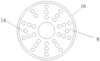
Fig. 2 is the utility model relates to a structure schematic diagram of the rotary disk of batching jar convenient to material mixes.
Fig. 3 is the utility model relates to a solid fixed ring's of batching jar structural schematic convenient to material mixes.
Reference numbers in the figures: the device comprises a shell 1, a motor 2, a first rotating shaft 3, a fixed ring 4, a supporting rod 5, a stirring shell 6, a spiral blade 7, a rotating ring 8, a rotating disk 9, a second rotating shaft 10, a stirring rod 11, a blanking pipe 12, a valve 13, a heating rod 14, a feeding pipe 15 and a first sliding block 16.
Detailed Description
The technical solutions in the embodiments of the present invention will be described clearly and completely with reference to the accompanying drawings in the embodiments of the present invention, and it is obvious that the described embodiments are only some embodiments of the present invention, not all embodiments.
Referring to fig. 1-3, a batching tank convenient for material mixing comprises a housing 1, a motor 2 is fixed on the upper side of the housing 1, a first rotating shaft 3 is fixedly connected to the output end of the motor 2, a fixing ring 4 is sleeved on the first rotating shaft 3, one end of a plurality of supporting rods 5 is fixed on the outer side of the fixing ring 4, a stirring shell 6 is fixedly connected to the other end of the supporting rods 5, the stirring shell 6 is rotatably connected with the housing 1, spiral blades 7 are arranged on the inner side wall of the stirring shell 6, the upper end of a rotating ring 8 is fixed at the bottom of the stirring shell 6, a rotating disk 9 is fixedly connected to the lower end of the rotating ring 8, one end of a second rotating shaft 10 is fixedly connected to the bottom of the stirring shell 6, a plurality of stirring rods 11 are fixed to the other end of the second rotating shaft 10, a blanking pipe 12 is fixedly connected to the bottom of the housing 1, a, the upper side of the rotating disk 9 is fixed with a heating rod 14, the upper side of the shell 1 is provided with a plurality of feeding pipes 15, the feeding pipes 15 are communicated with the shell 1, the inner wall of the bottom of the shell 1 is obliquely arranged, the rotating ring 8 is a cylinder which is communicated up and down, the supporting rods 5 are provided with 3, the supporting rods 5 are uniformly arranged at the outer side of the fixing ring 4, the plurality of stirring rods 11 are uniformly arranged on the second rotating shaft 10 in proportion, the first rotating shaft 3 is positioned right above the straight cylinder part of the stirring shell 6, the motor 2 is a positive and negative rotating motor, the bottom of the shell 1 is fixed with a universal wheel, a bearing is fixed at the rotating connection part of the first rotating shaft 3 and the shell 1, the fixing ring 4 is provided with a through hole matched with the first rotating shaft 3, the stirring shell 6 is of a funnel shape, the stirring shell 6 is fixed with a second sliding block, the inner wall of the shell 1 is provided with a first sliding groove matched with the, the bottom of stirring shell 6 is provided with the discharge gate, and the discharge gate is provided with 2, evenly is provided with a plurality of through-holes on the rotary disk 9 in proportion, and is provided with the second spout that matches with the first slider 16 in the rotary disk 9 outside on the inner wall of casing 1.
The working principle is as follows: when materials are mixed, the materials are poured into the mixing machine from the two feeding pipes 15 at the same time, the motor 2 is started, the motor 2 drives the first rotating shaft 3 to rotate, the first rotating shaft 3 drives the supporting rod 5 on the fixing ring 4 and further drives the stirring shell 6 to rotate, so that the second rotating shaft 10 positioned at the bottom of the stirring shell 6 can also rotate along with the stirring shell, the second rotating shaft 10 drives the stirring rod 11 to rotate, the rotating ring 8 connected with the stirring shell 6 drives the rotating disk 9 to rotate, when the materials enter, the materials are mixed in the straight cylinder of the stirring shell 6 and further are mixed along with the rotation of the spiral blades 7, then the materials fall onto the rotating disk 9 from the discharge port of the stirring shell 6, the rotating disk 9 rotates to mix the materials, the heating rod 14 heats the materials, the activity of some materials can be increased, the materials are beneficial to mixing, then the materials fall from the through hole on the rotating disk 9 and are stirred and, mix many times like this, can make the more even of mixture of material, puddler 11 also can effectually prevent the material sinking end, then opens valve 13 and derives the material after mixing from blanking pipe 12.
The above, only be the concrete implementation of the preferred embodiment of the present invention, but the protection scope of the present invention is not limited thereto, and any person skilled in the art is in the technical scope of the present invention, according to the technical solution of the present invention and the utility model, the concept of which is equivalent to replace or change, should be covered within the protection scope of the present invention.
Claims (6)
1. The utility model provides a batching jar convenient to material mixing, includes casing (1), its characterized in that, the upside of casing (1) is fixed with motor (2), the first pivot (3) of output fixedly connected with of motor (2), the cover is equipped with solid fixed ring (4) on first pivot (3), the outside of solid fixed ring (4) is fixed with the one end of a plurality of bracing pieces (5), the other end fixedly connected with stirring shell (6) of bracing piece (5), stirring shell (6) and casing (1) rotate to be connected, be provided with spiral leaf (7) on the inside wall of stirring shell (6), the bottom of stirring shell (6) is fixed with the upper end of swivel (8), the lower extreme fixedly connected with rotary disk (9) of swivel (8), the bottom fixedly connected with one end of second pivot (10) of stirring shell (6), the other end of second pivot (10) is fixed with a plurality of puddlers (11), the bottom fixedly connected with blanking pipe (12) of casing (1), be connected with valve (13) on blanking pipe (12), the outside fixedly connected with first slider (16) of rotary disk (9), the upside of rotary disk (9) is fixed with heating rod (14).
2. The dispensing canister for mixing materials as claimed in claim 1, wherein said housing (1) is provided with a plurality of feeding pipes (15) at the upper side, said feeding pipes (15) are connected to the housing (1), the inner wall of the bottom of said housing (1) is inclined, and said rotating ring (8) is a cylinder passing through the upper and lower parts.
3. The mixing tank convenient for material mixing as claimed in claim 1, wherein there are 3 support rods (5), and the support rods (5) are uniformly arranged outside the fixing ring (4), and a plurality of said stirring rods (11) are uniformly arranged on the second rotating shaft (10) in proportion, and said first rotating shaft (3) is located right above the straight cylinder part of the stirring shell (6).
4. The mixing tank convenient for material mixing as claimed in claim 1, wherein the motor (2) is a positive and negative rotation motor, the bottom of the casing (1) is fixed with a universal wheel, a bearing is fixed at the rotation joint of the first rotating shaft (3) and the casing (1), and the fixing ring (4) is provided with a through hole matched with the first rotating shaft (3).
5. The blending tank convenient for material mixing of claim 1, wherein the stirring shell (6) is of a funnel shape, a second sliding block is fixed on the stirring shell (6), a first sliding groove matched with the second sliding block is arranged on the inner wall of the shell (1), the spiral blade (7) is fixedly arranged on the inner wall of the straight cylinder part of the stirring shell (6), a discharge hole is formed in the bottom of the stirring shell (6), and 2 discharge holes are formed in the discharge hole.
6. The mixing tank of claim 1, characterized in that the rotating disk (9) is provided with a plurality of through holes in proportion, and the inner wall of the housing (1) is provided with a second sliding groove matched with the first sliding block (16) outside the rotating disk (9).
Priority Applications (1)
| Application Number | Priority Date | Filing Date | Title |
|---|---|---|---|
| CN201922125130.9U CN211133798U (en) | 2019-12-02 | 2019-12-02 | Batching jar convenient to material mixes |
Applications Claiming Priority (1)
| Application Number | Priority Date | Filing Date | Title |
|---|---|---|---|
| CN201922125130.9U CN211133798U (en) | 2019-12-02 | 2019-12-02 | Batching jar convenient to material mixes |
Publications (1)
| Publication Number | Publication Date |
|---|---|
| CN211133798U true CN211133798U (en) | 2020-07-31 |
Family
ID=71749201
Family Applications (1)
| Application Number | Title | Priority Date | Filing Date |
|---|---|---|---|
| CN201922125130.9U Expired - Fee Related CN211133798U (en) | 2019-12-02 | 2019-12-02 | Batching jar convenient to material mixes |
Country Status (1)
| Country | Link |
|---|---|
| CN (1) | CN211133798U (en) |
-
2019
- 2019-12-02 CN CN201922125130.9U patent/CN211133798U/en not_active Expired - Fee Related
Similar Documents
| Publication | Publication Date | Title |
|---|---|---|
| EP3741533B1 (en) | Mixer for synthetic quartz | |
| CN101385951A (en) | Vortex powder mixer | |
| CN215586176U (en) | High-efficient dispersator | |
| CN205055864U (en) | Batching bucket of wall function is scraped in area | |
| CN207856850U (en) | A kind of tea-leaf power taper agitating device | |
| CN215877099U (en) | Chinese herbal medicine mixing arrangement of misce bene | |
| CN206106095U (en) | A conveyor for concrete mixing | |
| CN211988295U (en) | Blendor for food processing | |
| CN211133798U (en) | Batching jar convenient to material mixes | |
| CN201279445Y (en) | Vortex powder mixer | |
| CN208244515U (en) | A kind of fertilising fertilizer mixed stirring device | |
| CN207520938U (en) | A kind of novel mixing machine | |
| CN213854199U (en) | Environment-friendly oil and rust removing agent batching device | |
| CN212383598U (en) | Even agitating unit of coating with dual mixing mechanism | |
| CN204768349U (en) | Mixer washing unit | |
| CN211800278U (en) | Food mixing machine | |
| CN208244600U (en) | A kind of V-Mixer | |
| CN209735456U (en) | caking mixer is prevented to fertilizer | |
| CN210303430U (en) | Stirrer for cleaning agent production equipment | |
| CN207591692U (en) | A kind of beverage agitating apparatus | |
| CN207056477U (en) | A kind of industrial chemicals agitating device | |
| CN208990624U (en) | Powder blenders | |
| CN212262946U (en) | Mixing arrangement of water resistance strong emulsion paint coating | |
| CN210993827U (en) | Chemical material stirring kettle | |
| CN214973668U (en) | Efficient powder mixer |
Legal Events
| Date | Code | Title | Description |
|---|---|---|---|
| GR01 | Patent grant | ||
| GR01 | Patent grant | ||
| CF01 | Termination of patent right due to non-payment of annual fee |
Granted publication date: 20200731 Termination date: 20201202 |
|
| CF01 | Termination of patent right due to non-payment of annual fee |