CN211131967U - Medical leg support frame - Google Patents
Medical leg support frame Download PDFInfo
- Publication number
- CN211131967U CN211131967U CN201922116537.5U CN201922116537U CN211131967U CN 211131967 U CN211131967 U CN 211131967U CN 201922116537 U CN201922116537 U CN 201922116537U CN 211131967 U CN211131967 U CN 211131967U
- Authority
- CN
- China
- Prior art keywords
- supporting rod
- rod
- leg support
- bending
- fixing member
- Prior art date
- Legal status (The legal status is an assumption and is not a legal conclusion. Google has not performed a legal analysis and makes no representation as to the accuracy of the status listed.)
- Active
Links
Images

Landscapes
- Invalid Beds And Related Equipment (AREA)
Abstract
The utility model discloses a medical leg support frame, which comprises a support frame body, wherein the support frame comprises a support part and a bearing part which is rotatably arranged at the upper end of the support part, the bearing part is a bearing rod with a bent part, and the bent part is provided with at least one; the supporting part comprises a supporting rod and a fixing device arranged on the supporting rod. A medical shank support frame device simple structure, use, accomodate the convenience, do not occupy the sick bed space, applicable in different physique patients.
Description
Technical Field
The utility model belongs to the technical field of medical equipment, concretely relates to medical shank support frame.
Background
In medical means such as disinfection of legs or rehabilitation of legs in cardiac surgery, the legs of a patient are often lifted off a bed plate in a manner of manual lifting or device supporting. In the current mode of operation, the artifical handheld lifting is too extravagant manpower, and when utilizing current device to support, because the width direction setting of sick bed is followed mostly to current device, uses this device will occupy great sick bed space, is unfavorable for doctor's operation and patient's motion. Patents CN202776852U and CN2892076Y all disclose relevant limb support frames, and most structures of two kinds of support frames in the existing patents are all arranged along the width direction of the sickbed when in use, so as to ensure the stability and occupy a larger space, and meanwhile, the two structures are complex, and are inconvenient to install and store, and are not beneficial to use.
SUMMERY OF THE UTILITY MODEL
In order to solve the problem, the utility model discloses a medical shank support frame, this device simple structure, use, accomodate the convenience, do not occupy the sick bed space, applicable in different physique patients.
In order to achieve the above purpose, the utility model adopts the following technical scheme: a medical leg support frame comprises a support frame body, wherein the support frame comprises a support part and a bearing part which is rotatably arranged at the upper end of the support part, the bearing part is a bearing rod with a bent part, and the bent part is provided with at least one; the supporting part comprises a supporting rod and a fixing device arranged on the supporting rod.
As a further improvement of the medical leg support frame of the utility model: the supporting rod is provided with an installation sleeve for installing the supporting rod at the upper end part of the supporting rod, and a reinforcing rod is further arranged between the supporting rod and the supporting rod.
As a further improvement of the medical leg support frame of the utility model: but the bracing piece is the telescopic link, and the cover is equipped with and rotates the cover on the bracing piece, the stiffener slope is connected between rotating cover and bearing rod.
As a further improvement of the medical leg support frame of the utility model: the radian of bending on the bearing portion is different, and the radian of bending on the bearing portion decreases from one end close to the support rod to one end far away from the support rod in sequence.
As a further improvement of the medical leg support frame of the utility model: the bending radians of the bending parts on the bearing part are different, and the bending parts with different bending radians are arranged in a staggered manner.
As a further improvement of the medical leg support frame of the utility model: the soft gasket is arranged at the bending part of the bearing rod, and air scattering holes are formed in the soft gasket and communicate the upper surface with the side surface of the soft gasket.
As a further improvement of the medical leg support frame of the utility model: the fixing device comprises a first fixing piece and a second fixing piece used for connecting the supporting rod and the first fixing piece, and the second fixing piece is rotatably connected with the first fixing piece.
As a further improvement of the medical leg support frame, the first fixing piece is of a -shaped structure, a clamping plate is arranged in the first fixing piece, the side plate of the first fixing piece is provided with a threaded hole, a bolt is rotatably arranged on the lower side surface of the clamping plate, the lower part of the bolt penetrates through the threaded hole and is sleeved with a nut cap, a counter bore is formed in the lower side surface of the clamping plate, and the upper end of the bolt is rotatably clamped in the counter bore.
As a further improvement of the medical leg support frame of the utility model, the second fixing piece is in a -shaped structure which is the same as the first fixing piece in structure, the extending direction of the second fixing piece is vertical to the extending direction of the first fixing piece, the second fixing piece wraps the supporting rod, and the second fixing piece, the supporting rod and the first fixing piece are mutually clamped and fixed through bolts.
Advantageous effects
Compared with the prior art, the utility model discloses following beneficial effect has:
first, a medical shank support frame, device simple structure, convenient to use, it only needs to fix the mounting in this device on the sick bed in the use, subsequent use, accomodate only need simple rotation, tensile can.
Second, a medical shank support frame, the bracing piece of telescopic structure, cover establish the bearing rod on the bracing piece, all guarantee with second mounting swing joint's bracing piece need not to dismantle when accomodating this device and can realize.
Third, a medical shank support frame, the support rod of this device sets up with the bracing piece is perpendicular, it is little to occupy sick bed top space, does not influence the staff and carries out other operations.
Fourth, a medical shank support frame, the kink that has a plurality of different radians on the bearing rod in this device to adapt to the patient of different physiques, the kink of radian size cross arrangement, in order to part the kink that the most suitable patient used, guarantee patient's comfort level, the setting of stiffener is in order to have the additional strengthening to the bearing piece.
Fifth, a medical shank support frame, the soft gasket that has the exhaust hole on the bearing pole improves patient's comfort level.
Drawings
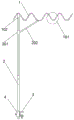
Fig. 1 is a schematic structural diagram of the present invention;
FIG. 2 is a schematic structural view of a fixing device of the present invention;
the labels in the figure are: 1. the device comprises a supporting rod, 101, a bending part, 102, an installation sleeve, 2, a supporting rod, 201, a rotating sleeve, 202, a reinforcing rod, 3, a first fixing piece, 301, a clamping block, 4 and a second fixing piece.
Detailed Description
The present invention will be further explained with reference to the accompanying drawings and specific embodiments, which are provided in the present embodiment on the premise of the technical solution of the present invention.
Example 1
The medical leg support frame in the embodiment comprises a support frame body, wherein the support frame body specifically comprises a support part and a support part which is rotatably arranged at the upper end of the support part, the support part is a support rod 1 with a bent part, namely the support rod 1 is a hard rod with a bent structure. Specifically, the support rod 1 has four concave portions, wherein the four concave portions have different bending radians, and the four concave portions are arranged in sequence according to the size of the bending radians. The supporting rod 1 is integrally connected with an installation sleeve 102 so as to enable the supporting rod 1 to be rotatably arranged on the supporting rod 2, and the installation sleeve 102 is provided with a fixing hole so as to be matched with an elastic bulge arranged on the supporting rod 2 to relatively fix the supporting rod 1 on the supporting rod 2. The supporting rod 2 is further provided with a rotating sleeve 201, and a reinforcing rod 202 is obliquely arranged between the rotating sleeve 201 and the supporting rod 1 so as to support and reinforce the supporting rod 1.
The supporting part comprises a supporting rod 2 and a fixing device arranged at the lower end of the supporting rod 2, wherein the fixing device comprises a first fixing piece 3 fixedly connected with the sickbed and a second fixing piece 4 rotatably connected with the supporting rod 2 and the first fixing piece 3, specifically, the first fixing piece 3 is in a '' structure, a clamping plate 301 is arranged in the first fixing piece 3, a threaded hole is formed in the lower side plate of the first fixing piece 3, a bolt is rotatably arranged on the lower side surface of the clamping plate 301, the lower portion of the bolt penetrates through the threaded hole and is sleeved with a nut cap, the distance between the clamping plate 301 and the lower side plate of the first fixing piece 3 is adjusted by adjusting the relative position of the nut cap and the bolt, and the clamping plate 301 and the first fixing piece 3 can be fixed on the sickbed.
The second fixing part 4 is of an -shaped structure which is the same as the first fixing part 3 in structure, the extending direction of the second fixing part 4 is perpendicular to the extending direction of the first fixing part 3, the second fixing part 4 wraps the supporting rod 2, and the second fixing part 4, the supporting rod 2 and the first fixing part 3 are clamped and fixed with each other through bolts.
Example 2
The specific structure of a medical leg support frame described in this embodiment is substantially the same as the specific structure of a medical leg support frame described in embodiment 1, and the difference is that: the support rod 2 is a telescopic rod, the rotating sleeve 201 is sleeved on the upper portion of the telescopic rod, and the fixing device is installed at the lower end portion of the lower portion of the telescopic rod. The supporting piece is provided with two bending parts with different bending radians, and the two bending parts are arranged in a crossed manner. The soft gasket is arranged at the bending part 101 of the bearing rod 1, and air scattering holes are formed in the soft gasket and communicate the upper surface with the side face of the soft gasket.
The above description is only a preferred embodiment of the present invention, and the present invention is not limited to the above embodiments, and although the present invention has been disclosed with the preferred embodiments, it is not limited to the present invention, and any skilled person in the art can make some modifications or equivalent changes without departing from the technical scope of the present invention.
Claims (9)
1. The utility model provides a medical leg support frame, includes the support frame body, its characterized in that: the supporting frame comprises a supporting part and a supporting part which is rotatably arranged at the upper end of the supporting part, the supporting part is a supporting rod with a bending part, and the bending part is provided with at least one bending part; the supporting part comprises a supporting rod and a fixing device arranged on the supporting rod.
2. A medical leg support as claimed in claim 1, wherein: the supporting rod is provided with an installation sleeve for installing the supporting rod at the upper end part of the supporting rod, and a reinforcing rod is further arranged between the supporting rod and the supporting rod.
3. A medical leg support as claimed in claim 2, wherein: but the bracing piece is the telescopic link, and the cover is equipped with and rotates the cover on the bracing piece, the stiffener slope is connected between rotating cover and bearing rod.
4. A medical leg support as claimed in claim 1, wherein: the radian of bending on the bearing portion is different, and the radian of bending on the bearing portion decreases from one end close to the support rod to one end far away from the support rod in sequence.
5. A medical leg support as claimed in claim 1, wherein: the bending radians of the bending parts on the bearing part are different, and the bending parts with different bending radians are arranged in a staggered manner.
6. A medical leg support as claimed in claim 4 or 5, wherein: the soft gasket is arranged at the bending part of the bearing rod, and air scattering holes are formed in the soft gasket and communicate the upper surface with the side surface of the soft gasket.
7. A medical leg support as claimed in claim 1, wherein: the fixing device comprises a first fixing piece and a second fixing piece used for connecting the supporting rod and the first fixing piece, and the second fixing piece is rotatably connected with the first fixing piece.
8. The medical leg support as claimed in claim 7, wherein the first fixing member is shaped like , a clamping plate is disposed in the first fixing member, a threaded hole is formed in a lower side plate of the first fixing member, a bolt is rotatably disposed on a lower side of the clamping plate, a nut cap is sleeved on a lower portion of the bolt and penetrates through the threaded hole, a counter bore is formed in a lower side surface of the clamping plate, and an upper end of the bolt is rotatably engaged in the counter bore.
9. The medical leg support according to claim 7, wherein the second fixing member has a structure of shape identical to the first fixing member, the extending direction of the second fixing member is perpendicular to the extending direction of the first fixing member, the second fixing member is wrapped on the supporting rod, and the second fixing member, the supporting rod and the first fixing member are fastened and fixed to each other by bolts.
Priority Applications (1)
| Application Number | Priority Date | Filing Date | Title |
|---|---|---|---|
| CN201922116537.5U CN211131967U (en) | 2019-12-02 | 2019-12-02 | Medical leg support frame |
Applications Claiming Priority (1)
| Application Number | Priority Date | Filing Date | Title |
|---|---|---|---|
| CN201922116537.5U CN211131967U (en) | 2019-12-02 | 2019-12-02 | Medical leg support frame |
Publications (1)
| Publication Number | Publication Date |
|---|---|
| CN211131967U true CN211131967U (en) | 2020-07-31 |
Family
ID=71772053
Family Applications (1)
| Application Number | Title | Priority Date | Filing Date |
|---|---|---|---|
| CN201922116537.5U Active CN211131967U (en) | 2019-12-02 | 2019-12-02 | Medical leg support frame |
Country Status (1)
| Country | Link |
|---|---|
| CN (1) | CN211131967U (en) |
Cited By (1)
| Publication number | Priority date | Publication date | Assignee | Title |
|---|---|---|---|---|
| CN112472463A (en) * | 2020-12-31 | 2021-03-12 | 王小燕 | Portable movable support for orthopedic sickbed and using method thereof |
-
2019
- 2019-12-02 CN CN201922116537.5U patent/CN211131967U/en active Active
Cited By (1)
| Publication number | Priority date | Publication date | Assignee | Title |
|---|---|---|---|---|
| CN112472463A (en) * | 2020-12-31 | 2021-03-12 | 王小燕 | Portable movable support for orthopedic sickbed and using method thereof |
Similar Documents
| Publication | Publication Date | Title |
|---|---|---|
| CN112057801A (en) | Lower limb rehabilitation training device | |
| CN211131967U (en) | Medical leg support frame | |
| CN212326812U (en) | Angle-adjustable orthopedic joint hanger | |
| CN211156335U (en) | Limbs suspension support for anorectal surgery | |
| CN209137006U (en) | T-shaped shoes | |
| CN212490196U (en) | Special hand bracket of microsurgery | |
| CN211067591U (en) | Nursing assistor for cardiothoracic surgery | |
| CN204501364U (en) | One lifts leg support | |
| CN214318481U (en) | Adjustable all-carbon breast bracket | |
| CN206730072U (en) | Bed upper and lower extremities exercise assist device | |
| CN206924224U (en) | A kind of infusion limb clamp plate used in pediatrics | |
| CN215129856U (en) | Universal skull traction bow assembly | |
| CN217430371U (en) | Multifunctional lower limb lifting device | |
| CN216168589U (en) | Orthopedic nursing leg traction correction device | |
| CN212439886U (en) | Lower limb rehabilitation training device | |
| CN213758805U (en) | Orthopedic limb traction frame | |
| CN217988283U (en) | Knee joint activity exerciser | |
| CN211049751U (en) | Orthopedic traction frame | |
| CN213098871U (en) | Wheelchair-assisted upper limb placing support | |
| CN215839759U (en) | Device for preventing foot drop | |
| CN210928232U (en) | Connecting device of elevator control cabinet | |
| CN219208517U (en) | Breathing machine pipeline mount | |
| CN213491834U (en) | Upper limb aerobic exercise rehabilitation device | |
| CN213641456U (en) | Traction frame for orthopedics clinic | |
| CN209596145U (en) | A kind of device for healing and training and rehabilitation equipment |
Legal Events
| Date | Code | Title | Description |
|---|---|---|---|
| GR01 | Patent grant | ||
| GR01 | Patent grant |