CN211118273U - Anti-blocking connecting pipe for irrigation and water conservancy irrigation - Google Patents
Anti-blocking connecting pipe for irrigation and water conservancy irrigation Download PDFInfo
- Publication number
- CN211118273U CN211118273U CN201922161935.9U CN201922161935U CN211118273U CN 211118273 U CN211118273 U CN 211118273U CN 201922161935 U CN201922161935 U CN 201922161935U CN 211118273 U CN211118273 U CN 211118273U
- Authority
- CN
- China
- Prior art keywords
- pipe
- irrigation
- closing plate
- square
- sleeve pipe
- Prior art date
- Legal status (The legal status is an assumption and is not a legal conclusion. Google has not performed a legal analysis and makes no representation as to the accuracy of the status listed.)
- Active
Links
Images

Landscapes
- Filtration Of Liquid (AREA)
Abstract
The utility model discloses a stifled takeover is prevented in irrigation and water conservancy irrigation, including square pipe, the bottom center department of square pipe is equipped with the sleeve pipe, sheathed tube center department is equipped with the bull stick, just the sleeve pipe passes through bull stick swing joint with square pipe, the fixed filter that is equipped with in one side of sheathed tube, sheathed tube bottom and top are equipped with first closing plate and second closing plate respectively. The utility model discloses a second closing plate receives to strike and drives the sleeve pipe upset, 90 degrees backs are rotated clockwise to the sleeve pipe, the inside center department that the filter is located square pipe continuously receives the water and strikes, filter the impurity that carries in the water, after the irrigation, the filter does not receive the water impact, first closing plate drives the anticlockwise upset of sleeve pipe under the effect of gravity, the impurity of filter bottom falls into the ditch automatically under the effect of gravity, should prevent stifled potential energy of takeover rational utilization water flow, can prevent stifled and take over impurity discharge automatically, alleviate artificial burden effectively.
Description
Technical Field
The utility model relates to an irrigation water pipe accessory technical field, concretely relates to stifled takeover is prevented in irrigation and water conservancy irrigation.
Background
The anti-blocking connecting pipe is an accessory used for connecting irrigation water pipes of a farmland, irrigation of farmland irrigation adopts modes of sprinkling irrigation, drip irrigation and the like, the irrigation mode has relatively high requirement on water quality, impurities such as waterweeds, gravels, soil and the like cannot exist, and the pipeline and a spray head are easy to block, so the anti-blocking connecting pipe is required to be used for avoiding pipeline blocking;
the prior art has the following defects: the anti-blocking connecting pipe has an anti-blocking function, impurities are filtered on one side of the filter plate to prevent blocking in the anti-blocking connecting pipe, the anti-blocking connecting pipe can be continuously used after being used for a period of time and the impurities in the anti-blocking connecting pipe are manually cleaned, and the anti-blocking connecting pipe which needs to be cleaned regularly increases the burden of workers.
SUMMERY OF THE UTILITY MODEL
The utility model aims at providing a stifled takeover is prevented in irrigation and water conservancy irrigation, the second closing plate receives to strike and drives the sleeve pipe upset, the sleeve pipe clockwise rotates 90 degrees backs, the inside center department that the filter is located square pipe continuously receives the water and strikes, filter the impurity that carries in the water, after the irrigation, the filter does not receive the water impact, first closing plate drives the anticlockwise upset of sleeve pipe under the effect of gravity, the impurity of filter bottom falls into the ditch automatically under the effect of gravity, should prevent stifled takeover rational utilization water mobile potential energy, can prevent stifled and take over impurity discharge automatically, alleviate artifical burden effectively, with the above-mentioned weak point in the solution technology.
In order to achieve the above object, the present invention provides the following technical solutions: the utility model provides a farmland irrigation anti-blocking takeover, includes square pipe, the bottom center department of square pipe is equipped with the sleeve pipe, sheathed tube center department is equipped with the bull stick, just the sleeve pipe passes through bull stick swing joint with square pipe, the fixed filter that is equipped with in sheathed tube one side, sheathed tube bottom and top are equipped with first closing plate and second closing plate respectively, the bottom both sides of square pipe all are equipped with square groove, just first closing plate and second closing plate respectively with two square groove phase-matchs, bottom one side of first closing plate is equipped with the checkpost, the fixed buckle that is equipped with of bottom opposite side of square pipe, just checkpost and buckle block.
Preferably, the inside at sleeve pipe both ends all is equipped with the bearing, just sleeve pipe and bull stick pass through bearing swing joint.
Preferably, the square bottom of the tube is close to the two sides of the sleeve and is fixedly provided with a connecting piece, and the two ends of the rotating rod are embedded into the two connecting pieces respectively and are in clearance fit with the inner wall of the embedded part of the connecting piece.
Preferably, the weight of the first sealing plate is greater than that of the second sealing plate, the bottom end of the first sealing plate and the top end of the second sealing plate are both provided with limiting frames, and the limiting frames are welded with the first sealing plate and the second sealing plate respectively.
Preferably, two the one end that square groove kept away from mutually all is equipped with Z shape breach, just spacing and Z shape breach phase-match, the top of Z shape breach is equipped with the glue film.
Preferably, the one end of square pipe is equipped with the inlet tube, the other end of square pipe is equipped with the drain pipe, just inlet tube and drain pipe all with square tub of turn-on connection.
Preferably, the one end that inlet tube and drain pipe kept away from mutually all is equipped with the flange, and two the flange welds with inlet tube and drain pipe respectively.
In the technical scheme, the utility model provides a technological effect and advantage:
the utility model discloses a second closing plate receives to strike and drives the sleeve pipe upset, 90 degrees backs of sleeve pipe clockwise rotation, the second closing plate is arranged in the square groove on square tub right side, first closing plate is arranged in the left square groove of square tub, the inside center department that the filter is arranged in square tub continuously receives the water and strikes, filter the impurity that carries in the water, after the irrigation, the filter is not strikeed by the water, first closing plate drives the anticlockwise upset of sleeve pipe under the effect of gravity, the filter overturns to the left square groove of square tub in, the impurity of bottom is automatic to fall into the ditch under the effect of gravity, compare with the stifled takeover of preventing of current needs artifical periodic cleaning, this potential energy that prevents stifled takeover rational utilization water flow, can prevent stifled and take over impurity discharge automatically, alleviate artifical burden effectively.
Drawings
In order to more clearly illustrate the embodiments of the present application or the technical solutions in the prior art, the drawings needed to be used in the embodiments will be briefly described below, and it is obvious that the drawings in the following description are only some embodiments described in the present invention, and other drawings can be obtained by those skilled in the art according to these drawings.
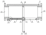
Fig. 1 is a longitudinal sectional view of the present invention.
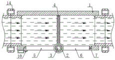
Fig. 2 is a view of a usage scenario of the present invention.
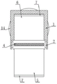
Fig. 3 is a left side longitudinal sectional view of the present invention.
Fig. 4 is an enlarged view of a portion a of fig. 1 in this embodiment.
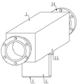
Fig. 5 is a schematic view of the overall structure of the present invention.
Description of reference numerals:
1. a square tube; 2. a sleeve; 3. a rotating rod; 4. a filter plate; 5. a first sealing plate; 6. a second sealing plate; 7. a limiting frame; 8. a square groove; 9. a Z-shaped notch; 10. a clip; 11. buckling; 12. a water inlet pipe; 13. a drain pipe; 14. a flange; 15. a connecting member.
Detailed Description
In order to make the technical solution of the present invention better understood by those skilled in the art, the present invention will be further described in detail with reference to the accompanying drawings.
The utility model provides a farmland irrigation anti-blocking connecting pipe as shown in figures 1-5, which comprises a square pipe 1, a sleeve 2 is arranged at the center of the bottom of the square pipe 1, a rotating rod 3 is arranged at the center of the sleeve 2, the sleeve 2 is movably connected with the square pipe 1 through the rotating rod 3, a filter plate 4 is fixedly arranged at one side of the sleeve 2, a first sealing plate 5 and a second sealing plate 6 are respectively arranged at the bottom and the top of the sleeve 2, square grooves 8 are respectively arranged at both sides of the bottom of the square pipe 1, the first sealing plate 5 and the second sealing plate 6 are respectively matched with the two square grooves 8, a clamp 10 is arranged at one side of the bottom of the first sealing plate 5, a buckle 11 is fixedly arranged at the other side of the bottom of the square pipe 1, and the clamp 10 is clamped with the buckle 11;
further, in the above technical solution, bearings are provided inside both ends of the sleeve 2, and the sleeve 2 is movably connected with the rotating rod 3 through the bearings, so that the sleeve 2 rotates more rapidly;
furthermore, in the above technical scheme, the two sides of the bottom of the square tube 1 close to the sleeve 2 are both fixedly provided with a connecting piece 15, and the two ends of the rotating rod 3 are respectively embedded in the two connecting pieces 15 and are in clearance fit with the inner wall of the embedded part of the connecting piece 15, so that the rotating rod 3 can be conveniently placed through the arranged connecting pieces 15;
further, in the above technical solution, the weight of the first sealing plate 5 is greater than that of the second sealing plate 6, the bottom end of the first sealing plate 5 and the top end of the second sealing plate 6 are both provided with limiting frames 7, and the two limiting frames 7 are respectively welded with the first sealing plate 5 and the second sealing plate 6, so that the first sealing plate 5 and the second sealing plate 6 are effectively limited by the provided limiting frames 7;
furthermore, in the above technical scheme, Z-shaped notches 9 are formed in the ends, far away from the two square grooves 8, of the limiting frame 7, the Z-shaped notches 9 are matched with the limiting frame 7, a glue layer is arranged on the tops of the Z-shaped notches 9, and the limiting frame 7 can be conveniently placed through the arranged Z-shaped notches 9;
further, in the above technical solution, one end of the square pipe 1 is provided with a water inlet pipe 12, the other end of the square pipe 1 is provided with a water outlet pipe 13, and the water inlet pipe 12 and the water outlet pipe 13 are both in conduction connection with the square pipe 1, so as to facilitate water inlet and water outlet;
further, in the above technical solution, flanges 14 are respectively disposed at ends of the water inlet pipe 12 and the water outlet pipe 13 away from each other, and the two flanges 14 are respectively welded to the water inlet pipe 12 and the water outlet pipe 13, so that the water inlet pipe 12 and the water outlet pipe 13 can be conveniently connected through the flanges 14;
the implementation mode is specifically as follows: the water inlet pipe 12 is connected with the water guide pipeline through the flange 14, the drain pipe 13 is connected with the spray head through the flange 14, the square pipe 1 is fixed at a water channel at the edge of a farmland through a bracket, during irrigation, the water guide pipeline supplies water to the inside of the square pipe 1 through the water inlet pipe 12, because inertia exists during water body transmission, when a small part of water just flows into the square pipe 1, the water passes through the filter plate 4 and falls into the water channel under the action of gravity, most of water body impacts the second sealing plate 6 under the action of inertia, the second sealing plate 6 is impacted to drive the sleeve 2 to turn over, the sleeve 2 rotates clockwise at the bottom of the square pipe 1 through the rotating rod 3, after rotating 90 degrees, the second sealing plate 6 is positioned in the square groove 8 at the right side of the square pipe 1, the first sealing plate 5 is positioned in the square groove 8 at the left side of the square pipe 1, the two limiting frames 7 are respectively clamped into the two, the filter plate 4 is positioned at the center of the square pipe 1 and is continuously impacted by water, impurities carried in the water are filtered, after irrigation is finished, the filter plate 4 is not impacted by the water, because the weight of the first sealing plate 5 is larger than that of the second sealing plate 6, the first sealing plate 5 drives the sleeve 2 to turn over anticlockwise under the action of gravity, the filter plate 4 turns over into the square groove 8 at the left side of the square pipe 1, the impurities at the bottom automatically fall into the water channel under the action of gravity, when the irrigation flow is small, the first sealing plate 5 can be manually turned to the square groove 8 at the left side of the square pipe 1, the toggle clip 10 is clamped into the buckle 11 to fix the first sealing plate 5 at the bottom of the square pipe 1, the anti-blocking connecting pipe reasonably utilizes the potential energy of water flowing, can automatically prevent blocking and discharge impurities out of the connecting pipe, effectively reduces the manual burden, this embodiment has specifically solved the problem that the anti-blocking structure that needs regularly clear up among the prior art aggravates artifical burden.
This practical theory of operation: second closing plate 6 receives to strike and drives the upset of sleeve pipe 2, sleeve pipe 2 clockwise rotation 90 degrees back, second closing plate 6 is arranged in square groove 8 on square 1 right side of pipe, first closing plate 5 is arranged in square 1 left square groove 8 of pipe, the inside center department that filter 4 is arranged in square 1 of pipe continuously receives the water and strikes, filter the impurity that carries in the water, after the irrigation, filter 4 does not receive the water and strikes, because the weight of first closing plate 5 is greater than the weight of second closing plate 6, first closing plate 5 drives the anticlockwise upset of sleeve pipe 2 under the effect of gravity, filter 4 overturns to square 1 left square groove 8 of pipe in, the impurity of bottom is automatic under the effect of gravity to fall into in the ditch.
While certain exemplary embodiments of the present invention have been described above by way of illustration only, it will be apparent to those of ordinary skill in the art that the described embodiments may be modified in various different ways without departing from the spirit and scope of the present invention. Accordingly, the drawings and description are illustrative in nature and should not be construed as limiting the scope of the invention.
Claims (7)
1. The utility model provides a stifled takeover is prevented in irrigation and water conservancy irrigation, includes square pipe (1), its characterized in that: the bottom center department of square pipe (1) is equipped with sleeve pipe (2), the center department of sleeve pipe (2) is equipped with bull stick (3), just sleeve pipe (2) and square pipe (1) are through bull stick (3) swing joint, the fixed filter (4) that are equipped with in one side of sleeve pipe (2), the bottom and the top of sleeve pipe (2) are equipped with first closing plate (5) and second closing plate (6) respectively, the bottom both sides of square pipe (1) all are equipped with square groove (8), just first closing plate (5) and second closing plate (6) respectively with two square groove (8) phase-matches, bottom one side of first closing plate (5) is equipped with checkpost (10), the fixed buckle (11) that is equipped with of bottom opposite side of square pipe (1), just checkpost (10) and buckle (11) block.
2. The anti-clogging connecting pipe for the irrigation and water conservancy irrigation as claimed in claim 1, wherein: the inside at sleeve pipe (2) both ends all is equipped with the bearing, just sleeve pipe (2) pass through bearing swing joint with bull stick (3).
3. The anti-clogging connecting pipe for the irrigation and water conservancy irrigation as claimed in claim 1, wherein: the two sides of the bottom of the square pipe (1) close to the sleeve (2) are fixedly provided with connecting pieces (15), and the two ends of the rotating rod (3) are embedded into the two connecting pieces (15) respectively and are in clearance fit with the inner wall of the embedded part of the connecting pieces (15).
4. The anti-clogging connecting pipe for the irrigation and water conservancy irrigation as claimed in claim 1, wherein: the weight of first closing plate (5) is greater than the weight of second closing plate (6), the bottom of first closing plate (5) and the top of second closing plate (6) all are equipped with spacing (7), and two spacing (7) weld with first closing plate (5) and second closing plate (6) respectively.
5. The anti-clogging connecting pipe for the irrigation and water conservancy irrigation as claimed in claim 4, wherein: two one end that square groove (8) kept away from mutually all is equipped with Z shape breach (9), just spacing (7) and Z shape breach (9) phase-match, the top of Z shape breach (9) is equipped with the glue film.
6. The anti-clogging connecting pipe for the irrigation and water conservancy irrigation as claimed in claim 1, wherein: the one end of square pipe (1) is equipped with inlet tube (12), the other end of square pipe (1) is equipped with drain pipe (13), just inlet tube (12) and drain pipe (13) all with square pipe (1) turn-on connection.
7. The anti-clogging connecting pipe for the irrigation and water conservancy irrigation as claimed in claim 6, wherein: one end that inlet tube (12) and drain pipe (13) kept away from mutually all is equipped with flange (14), and two flange (14) weld with inlet tube (12) and drain pipe (13) respectively.
Priority Applications (1)
| Application Number | Priority Date | Filing Date | Title |
|---|---|---|---|
| CN201922161935.9U CN211118273U (en) | 2019-12-06 | 2019-12-06 | Anti-blocking connecting pipe for irrigation and water conservancy irrigation |
Applications Claiming Priority (1)
| Application Number | Priority Date | Filing Date | Title |
|---|---|---|---|
| CN201922161935.9U CN211118273U (en) | 2019-12-06 | 2019-12-06 | Anti-blocking connecting pipe for irrigation and water conservancy irrigation |
Publications (1)
| Publication Number | Publication Date |
|---|---|
| CN211118273U true CN211118273U (en) | 2020-07-28 |
Family
ID=71692730
Family Applications (1)
| Application Number | Title | Priority Date | Filing Date |
|---|---|---|---|
| CN201922161935.9U Active CN211118273U (en) | 2019-12-06 | 2019-12-06 | Anti-blocking connecting pipe for irrigation and water conservancy irrigation |
Country Status (1)
| Country | Link |
|---|---|
| CN (1) | CN211118273U (en) |
Cited By (1)
| Publication number | Priority date | Publication date | Assignee | Title |
|---|---|---|---|---|
| CN116020195A (en) * | 2023-02-15 | 2023-04-28 | 中大明珠建工有限公司 | Filter equipment for irrigation |
-
2019
- 2019-12-06 CN CN201922161935.9U patent/CN211118273U/en active Active
Cited By (1)
| Publication number | Priority date | Publication date | Assignee | Title |
|---|---|---|---|---|
| CN116020195A (en) * | 2023-02-15 | 2023-04-28 | 中大明珠建工有限公司 | Filter equipment for irrigation |
Similar Documents
| Publication | Publication Date | Title |
|---|---|---|
| CN211118273U (en) | Anti-blocking connecting pipe for irrigation and water conservancy irrigation | |
| CN210543693U (en) | Inside automatic cleaning device of drain pipe for sewage | |
| CN110433561B (en) | Irrigation water conservancy pipeline filter equipment | |
| CN211091073U (en) | Farmland irrigation device convenient to installation | |
| CN205719648U (en) | A kind of sewage sampling device | |
| CN205437528U (en) | Foldable couplant collecting vat that can install fast | |
| CN208448814U (en) | Waste water treatment box in a kind of hole | |
| CN207846509U (en) | A kind of hydraulic engineering silt cleaning device | |
| CN207421641U (en) | A kind of hydraulic engineering pipeline | |
| CN206350389U (en) | Field irrigation pipeline is taken over | |
| CN209952345U (en) | Channel water filters water conservancy diversion and blocks dirty device | |
| CN208927721U (en) | A kind of dyeing waste water discharge management control system | |
| CN206821256U (en) | A kind of drip irrigation fertilizer efficiently applies mechanical device | |
| CN209792187U (en) | Cleaning structure in guide pipe of filling machine | |
| CN108580447B (en) | Valve end liner cleaning device | |
| CN207754279U (en) | A kind of root irrigation device | |
| CN201826372U (en) | One-time outpouring flushing device by collecting small water streams into large water volume | |
| CN206296239U (en) | A kind of automatic cleaning equipment for bearing machining | |
| CN208648876U (en) | A kind of water distributor of UASB stable flow type water distributor | |
| CN211012653U (en) | Rubber ball cleaning device | |
| CN218028113U (en) | Slag blocking device of sewage collection pipe network | |
| CN215596650U (en) | Anti-blocking joint device for irrigation and water conservancy irrigation water pipe | |
| CN209885363U (en) | Filtering mechanism of carbon element filter tube | |
| CN205077466U (en) | Multi -functional pipeline for hydraulic engineering | |
| CN210519691U (en) | Embedded anti-blocking double-hole drip irrigation belt |
Legal Events
| Date | Code | Title | Description |
|---|---|---|---|
| GR01 | Patent grant | ||
| GR01 | Patent grant |