CN211113670U - Supporting structure for steel structure special-shaped column frame - Google Patents
Supporting structure for steel structure special-shaped column frame Download PDFInfo
- Publication number
- CN211113670U CN211113670U CN201921977418.2U CN201921977418U CN211113670U CN 211113670 U CN211113670 U CN 211113670U CN 201921977418 U CN201921977418 U CN 201921977418U CN 211113670 U CN211113670 U CN 211113670U
- Authority
- CN
- China
- Prior art keywords
- support
- brace
- steel waist
- steel
- column frame
- Prior art date
- Legal status (The legal status is an assumption and is not a legal conclusion. Google has not performed a legal analysis and makes no representation as to the accuracy of the status listed.)
- Expired - Fee Related
Links
- 229910000831 Steel Inorganic materials 0.000 title claims abstract description 49
- 239000010959 steel Substances 0.000 title claims abstract description 49
- 238000010276 construction Methods 0.000 claims abstract description 8
- 238000013016 damping Methods 0.000 claims 2
- 206010066054 Dysmorphism Diseases 0.000 claims 1
- 230000035939 shock Effects 0.000 abstract description 3
- 238000010521 absorption reaction Methods 0.000 description 2
- 230000009286 beneficial effect Effects 0.000 description 2
- 238000010586 diagram Methods 0.000 description 2
- 230000000694 effects Effects 0.000 description 2
- 230000003796 beauty Effects 0.000 description 1
- 239000004567 concrete Substances 0.000 description 1
- 230000007547 defect Effects 0.000 description 1
- 230000007812 deficiency Effects 0.000 description 1
- 238000000034 method Methods 0.000 description 1
- 239000011150 reinforced concrete Substances 0.000 description 1
- 239000007787 solid Substances 0.000 description 1
Images


Landscapes
- Buildings Adapted To Withstand Abnormal External Influences (AREA)
Abstract
一种用于钢结构异形柱框架的支撑结构,它涉及建筑结构技术领域;基坑支护的内侧固定有型钢腰梁,首尾相接的两根型钢腰梁之间连接有角撑,型钢腰梁的内侧固定有网格状的水平支撑梁,水平支撑梁与型钢腰梁之间连接有端部斜撑,水平支撑梁上均布固定有若干立柱;所述的角撑和端部斜撑均包含内撑、外撑、法兰、减震弹簧和固定螺丝;所述的内撑插设于外撑中,外撑的一端和内撑上分别固定有法兰,两法兰之间连接有减震弹簧,角撑的两端通过固定螺丝分别与首尾相接的两根型钢腰梁固定连接,端部斜撑的两端通过固定螺丝分别与型钢腰梁和水平支撑梁固定连接。本实用新型施工环境好,可重复利用,支撑强度高,抗震性能好,适用于钢结构异形柱框架。

A support structure for a steel structure special-shaped column frame, which relates to the technical field of building structures; A grid-shaped horizontal support beam is fixed on the inner side of the beam, an end diagonal brace is connected between the horizontal support beam and the profiled steel waist beam, and a number of vertical columns are evenly fixed on the horizontal support beam; the angle braces and the end diagonal braces include The inner support, the outer support, the flange, the shock-absorbing spring and the fixing screw; the inner support is inserted into the outer support, one end of the outer support and the inner support are respectively fixed with a flange, and the connection between the two flanges is reduced. For the shock spring, the two ends of the angle brace are fixedly connected to the two steel waist beams connected end to end through fixing screws, and the two ends of the end diagonal brace are fixedly connected to the shaped steel waist beam and the horizontal support beam respectively through fixing screws. The utility model has good construction environment, can be reused, has high supporting strength and good seismic performance, and is suitable for special-shaped column frames of steel structures.
Description
技术领域technical field
本实用新型涉及建筑结构技术领域,具体涉及一种用于钢结构异形柱框架的支撑结构。The utility model relates to the technical field of building structures, in particular to a support structure for a special-shaped column frame of a steel structure.
背景技术Background technique
异形柱是指在满足结构刚度和承载力等要求的前提下,根据建筑使用功能,建筑设计布置的要求而采取不同几何形状截面的柱,诸如:T、L、Z 十字形等形状截面的柱,且截面各肢的肢高肢厚比不大于4的柱。砼异形柱结构将建筑美观、使用功能的灵活性与建筑结构合理的受力性能有机地结合起来,为用户提供了理想的居住环境,受到房地产开发商和广大用户的欢迎。Special-shaped column refers to the column with different geometric shape section according to the requirements of building use function and building design layout under the premise of meeting the requirements of structural rigidity and bearing capacity, such as: T, L, Z cross-shaped and other shape cross-section columns , and the ratio of limb height to limb thickness of each limb of the section is not greater than 4. The concrete special-shaped column structure organically combines the architectural beauty, the flexibility of the use function and the reasonable mechanical performance of the building structure, providing users with an ideal living environment and being welcomed by real estate developers and users.
传统的建筑基坑支撑采用钢筋混凝土基坑支撑,施工环境差,并且不可重复利用,支撑强度低,抗震性差,不适用于钢结构异形柱框架。The traditional construction foundation pit support adopts reinforced concrete foundation pit support, which has poor construction environment, cannot be reused, low support strength, and poor seismic resistance, which is not suitable for steel structure special-shaped column frame.
实用新型内容Utility model content
本实用新型的目的在于针对现有技术的缺陷和不足,提供一种结构简单、设计合理、使用方便的用于钢结构异形柱框架的支撑结构。The purpose of the utility model is to provide a support structure for steel structure special-shaped column frame with simple structure, reasonable design and convenient use, aiming at the defects and deficiencies of the prior art.
为实现上述目的,本实用新型采用的技术方案是:它包含基坑支护、型钢腰梁、角撑、水平支撑梁、端部斜撑和立柱;所述的基坑支护的内侧固定有型钢腰梁,首尾相接的两根型钢腰梁之间连接有角撑,型钢腰梁的内侧固定有网格状的水平支撑梁,水平支撑梁与型钢腰梁之间连接有端部斜撑,水平支撑梁上均布固定有若干立柱;所述的角撑和端部斜撑均包含内撑、外撑、法兰、减震弹簧和固定螺丝;所述的内撑插设于外撑中,外撑的一端和内撑上分别固定有法兰,两法兰之间连接有减震弹簧,角撑的两端通过固定螺丝分别与首尾相接的两根型钢腰梁固定连接,端部斜撑的两端通过固定螺丝分别与型钢腰梁和水平支撑梁固定连接。In order to achieve the above-mentioned purpose, the technical scheme adopted by the present utility model is: it includes foundation pit support, profiled steel waist beam, angle brace, horizontal support beam, end diagonal brace and upright column; the inner side of the foundation pit support is fixed with a The section steel waist beam, the two section steel waist beams connected end to end are connected with angle braces, the inner side of the section steel waist beam is fixed with a grid-shaped horizontal support beam, and the end diagonal braces are connected between the horizontal support beam and the section steel waist beam , a number of uprights are evenly distributed and fixed on the horizontal support beam; the angle braces and the end diagonal braces include inner braces, outer braces, flanges, shock-absorbing springs and fixing screws; the inner braces are inserted in the outer braces, One end of the outer support and the inner support are respectively fixed with flanges, and a shock-absorbing spring is connected between the two flanges. The two ends of the brace are respectively fixedly connected with the profiled steel waist beam and the horizontal support beam through fixing screws.
进一步地,所述的型钢腰梁和水平支撑梁上分别焊接有节点板,内撑和外撑的端部通过固定螺丝分别与节点板固定。Further, the section steel waist beam and the horizontal support beam are respectively welded with gusset plates, and the ends of the inner support and the outer support are respectively fixed to the gusset plates by fixing screws.
进一步地,所述的立柱通过螺栓与水平支撑梁固定连接。Further, the column is fixedly connected to the horizontal support beam through bolts.
进一步地,所述的基坑支护与型钢腰梁螺丝固定。Further, the foundation pit support is screwed to the profiled steel waist beam.
进一步地,所述的立柱的底部位于基坑支护的底部以下。Further, the bottom of the column is located below the bottom of the foundation pit support.
本实用新型的工作原理为:采用钢结构支撑,施工环境好,可重复利用、能快速形成刚度,通过设置角撑和端部斜撑提高支撑结构的抗扭性能,提高支撑的强度,通过角撑和端部斜撑上的减震弹簧减小型钢腰梁与型钢腰梁之间以及型钢腰梁与水平支撑梁之间的拉应力与压应力,起到减震作用,使异形柱框架支撑牢固,提高整体的抗震性能。The working principle of the utility model is as follows: the steel structure is used for support, the construction environment is good, it can be reused, and the rigidity can be formed quickly. The shock-absorbing springs on the braces and the end diagonal braces reduce the tensile stress and compressive stress between the section steel waist beam and the section steel waist beam and between the section steel waist beam and the horizontal support beam, and play a shock absorption effect, making the special-shaped column frame support Firm, improve the overall seismic performance.
采用上述结构后,本实用新型产生的有益效果为:本实用新型所述的一种用于钢结构异形柱框架的支撑结构,施工环境好,可重复利用,支撑强度高,抗震性能好,适用于钢结构异形柱框架,本实用新型具有结构简单、设置合理、制作成本低等优点。After the above structure is adopted, the beneficial effects of the present utility model are as follows: the supporting structure for the steel structure special-shaped column frame described in the present utility model has good construction environment, can be reused, high supporting strength, good seismic performance, and is suitable for For the special-shaped column frame of the steel structure, the utility model has the advantages of simple structure, reasonable setting, low production cost and the like.
附图说明Description of drawings
图1是本实用新型的立体结构图;Fig. 1 is the three-dimensional structure diagram of the present utility model;
图2是本实用新型的俯视结构图;Fig. 2 is the top view structure diagram of the present utility model;
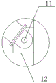
图3是图2中的A部放大图;Fig. 3 is the enlarged view of A part in Fig. 2;
图4是图2中的B部放大图。FIG. 4 is an enlarged view of part B in FIG. 2 .
附图标记说明:Description of reference numbers:
基坑支护1、型钢腰梁2、角撑3、十字水平支撑梁4、端部斜撑5、立柱6、内撑7、外撑8、法兰9、减震弹簧10、固定螺丝11、节点板12、螺栓13。Foundation pit support 1, section
具体实施方式Detailed ways
为了更清楚地说明本实用新型实施例或现有技术中的技术方案,下面将对实施例或现有技术描述中所需要使用的附图作简单地介绍,显而易见地,下面描述中的附图仅仅是本实用新型的一些实施例,对于本领域普通技术人员来讲,在不付出创造性劳动性的前提下,还可以根据这些附图获得其他的附图。In order to more clearly illustrate the embodiments of the present utility model or the technical solutions in the prior art, the following briefly introduces the accompanying drawings that need to be used in the description of the embodiments or the prior art. Obviously, the accompanying drawings in the following description These are just some embodiments of the present invention, and for those of ordinary skill in the art, other drawings can also be obtained from these drawings without any creative effort.
参看如图1——图4所示,本具体实施方式采用如下技术方案:它包含基坑支护1、型钢腰梁2、角撑3、水平支撑梁4、端部斜撑5和立柱6;所述的基坑支护1的内侧固定有型钢腰梁2,首尾相接的两根型钢腰梁2之间连接有角撑3,型钢腰梁2的内侧固定有网格状的水平支撑梁4,采用钢结构支撑,施工环境好,可重复利用、能快速形成刚度。Referring to Figure 1--As shown in Figure 4, this specific embodiment adopts the following technical scheme: it includes foundation pit support 1, profiled
水平支撑梁4与型钢腰梁2之间连接有端部斜撑5,水平支撑梁4上均布固定有若干立柱6;所述的角撑3和端部斜撑5均包含内撑7、外撑8、法兰9、减震弹簧10和固定螺丝11;所述的内撑7插设于外撑8中,外撑8的一端和内撑7上分别固定有法兰9,两法兰9之间连接有减震弹簧10,角撑3的两端通过固定螺丝11分别与首尾相接的两根型钢腰梁2固定连接,端部斜撑5的两端通过固定螺丝11分别与型钢腰梁2和水平支撑梁4固定连接,通过设置角撑3和端部斜撑5提高支撑结构的抗扭性能,提高支撑的强度,通过角撑3和端部斜撑5上的减震弹簧10减小型钢腰梁2与型钢腰梁2之间以及型钢腰梁2与水平支撑梁4之间的拉应力与压应力,起到减震作用,使异形柱框架支撑牢固,提高整体的抗震性能。An end
所述的型钢腰梁2和水平支撑梁4上分别焊接有节点板12,内撑7和外撑8的端部通过固定螺丝11分别与节点板12固定,用于固定角撑3和端部斜撑5。The section
所述的立柱6通过螺栓13与水平支撑梁4固定连接,立柱6的底部位于基坑支护1的底部以下,扎实基础,用于主要承重。The
所述的基坑支护1与型钢腰梁2螺丝固定。The foundation pit support 1 and the profiled
采用上述结构后,本具体实施方式产生的有益效果为:本具体实施方式所述的一种用于钢结构异形柱框架的支撑结构,施工环境好,可重复利用,支撑强度高,抗震性能好,适用于钢结构异形柱框架,本具体实施方式具有结构简单、设置合理、制作成本低等优点。After the above structure is adopted, the beneficial effects of this specific embodiment are: the supporting structure for a steel structure special-shaped column frame described in this specific embodiment has good construction environment, can be reused, high supporting strength, and good seismic performance. , suitable for steel structure special-shaped column frame, the specific embodiment has the advantages of simple structure, reasonable setting, low production cost and the like.
以上显示和描述了本实用新型的基本原理和主要特征以及本实用新型的优点。本行业的技术人员应该了解,本实用新型不受上述实施例的限制,上述实施例和说明书中描述的只是说明本实用新型的原理,在不脱离本实用新型精神和范围的前提下,本实用新型还会有各种变化和改进,这些变化和改进都落入要求保护的本实用新型范围内。本实用新型要求保护范围由所附的权利要求书及其等效物界定。The basic principles and main features of the present invention and the advantages of the present invention are shown and described above. It should be understood by those skilled in the art that the present invention is not limited by the above-mentioned embodiments. The above-mentioned embodiments and descriptions only illustrate the principles of the present invention. Without departing from the spirit and scope of the present invention, the present invention The new model will also have various changes and improvements, which all fall within the scope of the claimed invention. The claimed scope of the present invention is defined by the appended claims and their equivalents.
Claims (5)
Priority Applications (1)
| Application Number | Priority Date | Filing Date | Title |
|---|---|---|---|
| CN201921977418.2U CN211113670U (en) | 2019-11-15 | 2019-11-15 | Supporting structure for steel structure special-shaped column frame |
Applications Claiming Priority (1)
| Application Number | Priority Date | Filing Date | Title |
|---|---|---|---|
| CN201921977418.2U CN211113670U (en) | 2019-11-15 | 2019-11-15 | Supporting structure for steel structure special-shaped column frame |
Publications (1)
| Publication Number | Publication Date |
|---|---|
| CN211113670U true CN211113670U (en) | 2020-07-28 |
Family
ID=71702015
Family Applications (1)
| Application Number | Title | Priority Date | Filing Date |
|---|---|---|---|
| CN201921977418.2U Expired - Fee Related CN211113670U (en) | 2019-11-15 | 2019-11-15 | Supporting structure for steel structure special-shaped column frame |
Country Status (1)
| Country | Link |
|---|---|
| CN (1) | CN211113670U (en) |
-
2019
- 2019-11-15 CN CN201921977418.2U patent/CN211113670U/en not_active Expired - Fee Related
Similar Documents
| Publication | Publication Date | Title |
|---|---|---|
| CN205296573U (en) | Assembly type structure load -bearing wall panel | |
| CN105064527B (en) | A kind of steel loop damping energy dissipation brace system and design method | |
| CN105888131B (en) | A kind of bending yield type energy dissipating truss | |
| CN101245611A (en) | Semi-rigid connection-buckling-restrained braced steel frame structures | |
| CN110670483A (en) | A kind of steel pipe concrete composite main tower | |
| CN204098222U (en) | A kind of high-strength anti-shock steel structure technique | |
| CN107989180A (en) | A kind of accentric support frame | |
| CN214884850U (en) | Outer cantilevered large-span arc-shaped variable-section box-shaped steel beam structure where the inner ring intersects | |
| CN101215854A (en) | Beam-column hinged-buckling restrained braced steel frame structures | |
| CN211113670U (en) | Supporting structure for steel structure special-shaped column frame | |
| CN203145193U (en) | Welding-combination type steel concrete specially-shaped column and steel girder semi-rigid node | |
| CN209941896U (en) | Assembled center support with energy dissipation component for steel pipe recycled concrete structure | |
| CN207905104U (en) | A kind of assembled architecture truss structure | |
| CN207597584U (en) | Accentric support frame | |
| CN211171623U (en) | Steel pipe concrete combined main tower | |
| CN210459529U (en) | A bamboo-wood building beam-column CFRP steel joint | |
| CN108533047A (en) | Timber structure beam column combines energy dissipation node | |
| CN211690769U (en) | Steel structure supporting node component | |
| CN206015700U (en) | A kind of raft foundation steelframe support | |
| CN212866332U (en) | Steel construction factory building | |
| CN211257553U (en) | Steel-wood combined trapezoidal luxury roof truss based on node connection | |
| CN204370614U (en) | The split type combined concrete shear wall of built-in round steel pipe cross section bearing diagonal | |
| CN209114609U (en) | A kind of full Baogang's frame-core tube-Special-Shaped Column architectural structure system of assembled | |
| CN209872068U (en) | A frame-type light composite car floor | |
| CN203514206U (en) | Vertical column for incremental launching construction of large-span steel structure bridge |
Legal Events
| Date | Code | Title | Description |
|---|---|---|---|
| GR01 | Patent grant | ||
| GR01 | Patent grant | ||
| CF01 | Termination of patent right due to non-payment of annual fee | ||
| CF01 | Termination of patent right due to non-payment of annual fee |
Granted publication date: 20200728 |