CN211104224U - Heated board cutting device - Google Patents
Heated board cutting device Download PDFInfo
- Publication number
- CN211104224U CN211104224U CN201921460193.3U CN201921460193U CN211104224U CN 211104224 U CN211104224 U CN 211104224U CN 201921460193 U CN201921460193 U CN 201921460193U CN 211104224 U CN211104224 U CN 211104224U
- Authority
- CN
- China
- Prior art keywords
- cutting device
- heated board
- push
- plate
- bottom plate
- Prior art date
- Legal status (The legal status is an assumption and is not a legal conclusion. Google has not performed a legal analysis and makes no representation as to the accuracy of the status listed.)
- Active
Links
Images

Landscapes
- Perforating, Stamping-Out Or Severing By Means Other Than Cutting (AREA)
- Lining Or Joining Of Plastics Or The Like (AREA)
Abstract
The utility model discloses a heated board cutting device, including the bottom plate, two parallel arrangement's of bottom plate upside fixed connection riser, normal running fit joint substrate between two risers, two fixed plates are connected to sliding fit on the base plate, all are equipped with cutting device on every fixed plate, at one of them riser one side is equipped with the pendulous device that is used for control substrate the bottom plate upside still is equipped with clamping device. The utility model has the advantages that: the utility model provides a mode that heated board cutting device passes through swing cutting device carries out two-sided cutting to the heated board simultaneously, and the cutting uniformity is high, and the depth of parallelism of the relative both sides in cutting back is high, and the distance between two cutting device can be adjusted, can be fit for the not unidimensional heated board of price.
Description
Technical Field
The utility model relates to an heated board production facility technical field especially relates to a heated board cutting device.
Background
At present, the heated board need be cut into the rectangular plate of equidimension with it in process of production, conveniently assembles it on the outer wall like this, keeps warm to the outer wall, and adopts the cutting knife single face to cut it among the prior art, and not only cutting speed is slow like this, and the depth of parallelism of two opposite faces is relatively poor moreover, is unfavorable for the later stage to assemble on the outer wall.
SUMMERY OF THE UTILITY MODEL
The utility model aims at solving the defects existing in the prior art and providing a heat insulation board cutting device.
In order to achieve the above purpose, the utility model adopts the following technical scheme:
the utility model provides an insulation board cutting device, includes the bottom plate, two parallel arrangement's of bottom plate upside fixed connection riser, normal running fit connects the base plate between two risers, and sliding fit connects two fixed plates on the base plate, all is equipped with cutting device on every fixed plate, is equipped with the pendulous device that is used for control substrate in one side of one of them riser, still is equipped with clamping device at the bottom plate upside.
Preferably, the cutting device comprises a motor, and a cutting blade is mounted on a main shaft of the motor.
Preferably, the swinging device comprises a rotating disc, the rotating disc is connected with the base plate, a swinging rod is arranged on one side of the rotating disc, and the side of the swinging rod is hinged with the push-pull device.
Preferably, the push-pull device comprises a push-pull air cylinder, the push-pull air cylinder is hinged to one side of the vertical plate through a pin shaft, and a piston rod of the push-pull air cylinder is hinged to the swinging rod.
Preferably, the clamping device comprises a first mounting plate and a second mounting plate which are arranged in parallel, a square groove is formed in the upper side of the first mounting plate, a clamping cylinder is installed on one side of the second mounting plate, and a piston rod of the clamping cylinder is fixedly connected with a clamping plate.
The utility model has the advantages that: the utility model provides a mode that heated board cutting device passes through swing cutting device carries out two-sided cutting to the heated board simultaneously, and the cutting uniformity is high, and the depth of parallelism of the relative both sides in cutting back is high, and the distance between two cutting device can be adjusted, can be fit for the not unidimensional heated board of price.
Drawings
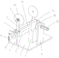
Fig. 1 is a schematic view of a basic structure of a heat insulation board cutting device provided by the present invention;
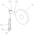
FIG. 2 is a schematic view of the basic structure of the swing device;
FIG. 3 is a schematic view of a connection structure of a substrate and a slider.
Detailed Description
In order to make the objects, technical solutions and advantages of the present invention more clearly understood, the present invention is further described in detail below with reference to the accompanying drawings and embodiments. It should be understood that the specific embodiments described herein are merely illustrative of the invention and are not intended to limit the invention.
Example 1
As shown in fig. 1-3, the utility model provides a pair of heated board cutting device, including bottom plate 1, 1 upside welding of bottom plate two parallel arrangement's riser 2, 2 one sides of every riser all are equipped with the rotation hole, rotate downthehole equal normal running fit at every and connect axis of rotation 21, two coaxial settings of axis of rotation 21, fixed connection base plate 3 between two axis of rotation 21, base plate 3 can rotate between two risers 2 through axis of rotation 21.
A swing device 9 for controlling the base plate 3 is arranged on one side of one of the vertical plates 2, the swing device 9 comprises a rotating disc 91, the rotating disc 91 is coaxially fixed on one of the rotating shafts 21, a swing rod 92 is fixedly connected on one side of the rotating disc 91, one end of the swing rod 92 is provided with a rotating groove 921, and a rotating block 93 is hinged in the rotating groove 921. The utility model provides a pair of heated board cutting device still includes push-and-pull device, and push-and-pull device includes push-and-pull cylinder 94, push-and-pull cylinder 94's tip fixed connection rotor plate 95, and rotor plate 95 articulates in riser 2 one side, push-and-pull cylinder 94's piston rod and rotor block 93 fixed connection through round pin axle 96.
Be equipped with spout 31 on the base plate 3, two slides 4 of sliding connection in the spout 31, slide 4 includes slider 41, slider 41 sets up in spout 31 and can follow spout 31 reciprocating sliding, slider 41 upside fixed connection slide 42, the symmetry is equipped with two screw holes on slide 42, at every threaded hole equal threaded connection screw 42, the screw 42 of screwing can prevent that slide 4 from removing in spout 31. Every fixed plate 5 of the vertical setting of the equal fixed connection of slide 42 upside all is equipped with cutting device on every fixed plate 5, and cutting device includes motor 6, and motor 6's main shaft passes in the hole of stepping down of fixed plate 5, is equipped with cutting piece 61 on motor 6's the main shaft.
The upper side of the bottom plate 1 is also provided with a clamping device. Clamping device includes parallel arrangement's first mounting panel 7 and second mounting panel 8, and first mounting panel 7 all welds at bottom plate 1 upside with second mounting panel 8, and first mounting panel 7 upside is equipped with square groove 71, is equipped with die clamping cylinder 81 on second mounting panel 8 one side, and fixed connection clamp plate 82 on the piston rod of die clamping cylinder 81, clamp plate 82 sets up with square groove 71 relatively.
Use the utility model provides a during heated board cutting device, with the heated board vertical put in square groove 71 department, promote clamp plate 82 through die clamping cylinder 81 and press from both sides the heated board tightly, drive base plate 3 through pendulous device 9 and rotate for cutting device rotates towards the heated board, thereby to the heated board cutting, slides the position that can adjust two cutting pieces 61 in spout 31 through slider 41, is fit for cutting not unidimensional heated board.
Claims (5)
1. The utility model provides an insulation board cutting device, its characterized in that includes bottom plate (1), two parallel arrangement's of bottom plate (1) upside fixed connection riser (2), normal running fit connects base plate (3) between two riser (2), and sliding fit connects two fixed plates (5) on base plate (3), all is equipped with cutting device on every fixed plate (5), one of them riser (2) one side is equipped with pendulous device (9) that are used for control substrate (3) bottom plate (1) upside still is equipped with clamping device.
2. The insulation board cutting device according to claim 1, characterized in that: the cutting device comprises a motor (6), and a cutting blade (61) is arranged on a main shaft of the motor (6).
3. The insulation board cutting device according to claim 1, characterized in that: the swinging device (9) comprises a rotating disc (91), the rotating disc (91) is connected with the base plate (3), a swinging rod (92) is arranged on one side of the rotating disc (91), and one side of the swinging rod (92) is hinged with a push-pull device.
4. The insulation board cutting device according to claim 2, characterized in that: the push-pull device comprises a push-pull air cylinder (94), the push-pull air cylinder (94) is hinged to one side of the vertical plate (2) through a pin shaft (96), and a piston rod of the push-pull air cylinder (94) is hinged to the swinging rod (92).
5. The insulation board cutting device according to claim 1, characterized in that: clamping device is equipped with square groove (71) including parallel arrangement's first mounting panel (7) and second mounting panel (8) first mounting panel (7) upside second mounting panel (8) one side is equipped with die clamping cylinder (81), fixed connection clamp plate (82) on the piston rod of die clamping cylinder (81).
Priority Applications (1)
| Application Number | Priority Date | Filing Date | Title |
|---|---|---|---|
| CN201921460193.3U CN211104224U (en) | 2019-09-04 | 2019-09-04 | Heated board cutting device |
Applications Claiming Priority (1)
| Application Number | Priority Date | Filing Date | Title |
|---|---|---|---|
| CN201921460193.3U CN211104224U (en) | 2019-09-04 | 2019-09-04 | Heated board cutting device |
Publications (1)
| Publication Number | Publication Date |
|---|---|
| CN211104224U true CN211104224U (en) | 2020-07-28 |
Family
ID=71721996
Family Applications (1)
| Application Number | Title | Priority Date | Filing Date |
|---|---|---|---|
| CN201921460193.3U Active CN211104224U (en) | 2019-09-04 | 2019-09-04 | Heated board cutting device |
Country Status (1)
| Country | Link |
|---|---|
| CN (1) | CN211104224U (en) |
Cited By (1)
| Publication number | Priority date | Publication date | Assignee | Title |
|---|---|---|---|---|
| CN113232052A (en) * | 2021-04-07 | 2021-08-10 | 向小明 | Building external wall insulation board construction system |
-
2019
- 2019-09-04 CN CN201921460193.3U patent/CN211104224U/en active Active
Cited By (1)
| Publication number | Priority date | Publication date | Assignee | Title |
|---|---|---|---|---|
| CN113232052A (en) * | 2021-04-07 | 2021-08-10 | 向小明 | Building external wall insulation board construction system |
Similar Documents
| Publication | Publication Date | Title |
|---|---|---|
| CN110757298A (en) | Casting polishing device | |
| CN211104224U (en) | Heated board cutting device | |
| CN106553240B (en) | Woodworking rotary coaxial double-arm profiling edge milling machine | |
| CN211029041U (en) | Glass bottle mould closes seam face adds clamping apparatus | |
| CN210334563U (en) | Adjustable interval's panel processing frame | |
| CN110666545B (en) | Axial cutting device of nonrust steel pipe | |
| CN107790500A (en) | A kind of flat axle is automatically positioned roll change clamp | |
| CN216097640U (en) | Peripheral milling fixture of axle fist portion | |
| CN211028405U (en) | Chamfering device for two ends of piston pin | |
| CN204819018U (en) | Adjustable gear face burring device | |
| CN210817992U (en) | High-frequency nanosecond optical fiber laser cutting device for battery pole piece | |
| CN106584062A (en) | Automobile transmission trial-production assembly table | |
| CN208713542U (en) | A kind of lathe coolant liquid delivery pipe | |
| CN204843741U (en) | Gear face burring device | |
| CN220575720U (en) | Sheet metal machining clamping device | |
| CN211207906U (en) | A anti-toppling device for marketing show board | |
| CN214686164U (en) | Frock is fixed to water-cooling disc | |
| CN213225183U (en) | Fixed mechanical fixture for machining | |
| CN208391337U (en) | A kind of cellular li-ion battery welding fixture | |
| CN205329179U (en) | Copper anode mills ear device | |
| CN220052110U (en) | Energy-saving board production cutting device | |
| CN212191678U (en) | Plasma cutting machine | |
| CN203316973U (en) | Automated welding tooling for valve | |
| CN209035867U (en) | A kind of automobile welding and assembling clamp turntable | |
| CN216066336U (en) | Rotating page plate assembling equipment |
Legal Events
| Date | Code | Title | Description |
|---|---|---|---|
| GR01 | Patent grant | ||
| GR01 | Patent grant |