CN211075601U - Intelligent charging equipment for electric vehicle - Google Patents
Intelligent charging equipment for electric vehicle Download PDFInfo
- Publication number
- CN211075601U CN211075601U CN201921420265.1U CN201921420265U CN211075601U CN 211075601 U CN211075601 U CN 211075601U CN 201921420265 U CN201921420265 U CN 201921420265U CN 211075601 U CN211075601 U CN 211075601U
- Authority
- CN
- China
- Prior art keywords
- module
- charging
- detection module
- electronic switch
- mcu control
- Prior art date
- Legal status (The legal status is an assumption and is not a legal conclusion. Google has not performed a legal analysis and makes no representation as to the accuracy of the status listed.)
- Active
Links
Images


Classifications
-
- Y—GENERAL TAGGING OF NEW TECHNOLOGICAL DEVELOPMENTS; GENERAL TAGGING OF CROSS-SECTIONAL TECHNOLOGIES SPANNING OVER SEVERAL SECTIONS OF THE IPC; TECHNICAL SUBJECTS COVERED BY FORMER USPC CROSS-REFERENCE ART COLLECTIONS [XRACs] AND DIGESTS
- Y02—TECHNOLOGIES OR APPLICATIONS FOR MITIGATION OR ADAPTATION AGAINST CLIMATE CHANGE
- Y02T—CLIMATE CHANGE MITIGATION TECHNOLOGIES RELATED TO TRANSPORTATION
- Y02T10/00—Road transport of goods or passengers
- Y02T10/60—Other road transportation technologies with climate change mitigation effect
- Y02T10/70—Energy storage systems for electromobility, e.g. batteries
-
- Y—GENERAL TAGGING OF NEW TECHNOLOGICAL DEVELOPMENTS; GENERAL TAGGING OF CROSS-SECTIONAL TECHNOLOGIES SPANNING OVER SEVERAL SECTIONS OF THE IPC; TECHNICAL SUBJECTS COVERED BY FORMER USPC CROSS-REFERENCE ART COLLECTIONS [XRACs] AND DIGESTS
- Y02—TECHNOLOGIES OR APPLICATIONS FOR MITIGATION OR ADAPTATION AGAINST CLIMATE CHANGE
- Y02T—CLIMATE CHANGE MITIGATION TECHNOLOGIES RELATED TO TRANSPORTATION
- Y02T10/00—Road transport of goods or passengers
- Y02T10/60—Other road transportation technologies with climate change mitigation effect
- Y02T10/7072—Electromobility specific charging systems or methods for batteries, ultracapacitors, supercapacitors or double-layer capacitors
-
- Y—GENERAL TAGGING OF NEW TECHNOLOGICAL DEVELOPMENTS; GENERAL TAGGING OF CROSS-SECTIONAL TECHNOLOGIES SPANNING OVER SEVERAL SECTIONS OF THE IPC; TECHNICAL SUBJECTS COVERED BY FORMER USPC CROSS-REFERENCE ART COLLECTIONS [XRACs] AND DIGESTS
- Y02—TECHNOLOGIES OR APPLICATIONS FOR MITIGATION OR ADAPTATION AGAINST CLIMATE CHANGE
- Y02T—CLIMATE CHANGE MITIGATION TECHNOLOGIES RELATED TO TRANSPORTATION
- Y02T90/00—Enabling technologies or technologies with a potential or indirect contribution to GHG emissions mitigation
- Y02T90/10—Technologies relating to charging of electric vehicles
- Y02T90/12—Electric charging stations
-
- Y—GENERAL TAGGING OF NEW TECHNOLOGICAL DEVELOPMENTS; GENERAL TAGGING OF CROSS-SECTIONAL TECHNOLOGIES SPANNING OVER SEVERAL SECTIONS OF THE IPC; TECHNICAL SUBJECTS COVERED BY FORMER USPC CROSS-REFERENCE ART COLLECTIONS [XRACs] AND DIGESTS
- Y02—TECHNOLOGIES OR APPLICATIONS FOR MITIGATION OR ADAPTATION AGAINST CLIMATE CHANGE
- Y02T—CLIMATE CHANGE MITIGATION TECHNOLOGIES RELATED TO TRANSPORTATION
- Y02T90/00—Enabling technologies or technologies with a potential or indirect contribution to GHG emissions mitigation
- Y02T90/10—Technologies relating to charging of electric vehicles
- Y02T90/14—Plug-in electric vehicles
-
- Y—GENERAL TAGGING OF NEW TECHNOLOGICAL DEVELOPMENTS; GENERAL TAGGING OF CROSS-SECTIONAL TECHNOLOGIES SPANNING OVER SEVERAL SECTIONS OF THE IPC; TECHNICAL SUBJECTS COVERED BY FORMER USPC CROSS-REFERENCE ART COLLECTIONS [XRACs] AND DIGESTS
- Y02—TECHNOLOGIES OR APPLICATIONS FOR MITIGATION OR ADAPTATION AGAINST CLIMATE CHANGE
- Y02T—CLIMATE CHANGE MITIGATION TECHNOLOGIES RELATED TO TRANSPORTATION
- Y02T90/00—Enabling technologies or technologies with a potential or indirect contribution to GHG emissions mitigation
- Y02T90/10—Technologies relating to charging of electric vehicles
- Y02T90/16—Information or communication technologies improving the operation of electric vehicles
Abstract
The utility model discloses an intelligent charging device for electric vehicles, which comprises a shell, wherein an MCU control module, an RFID read-write module, a voltage detection module, a RTC module, a power supply module and at least one charging loop control unit are arranged in the shell, the charging loop control unit comprises an electronic switch module, a fault detection module and a current detection module, the RFID read-write module, the voltage detection module, the RTC module, the electronic switch module, the fault detection module and the current detection module are respectively connected with the MCU control module, an AC input power supply is connected with a charging socket through the electronic switch module, the charging socket is arranged on the shell, the fault detection module is connected with the electronic switch module to detect whether the voltage output of the electronic switch module is normal or not, the current detection module is connected with the electronic switch module to detect the output current of the electronic switch module, the voltage detection module is used for detecting the input voltage of the, the power module supplies power to each module.
Description
Technical Field
The utility model relates to an electric motor car technical field that charges especially relates to an electric motor car intelligent charging equipment.
Background
At present, the new energy field is more and more concerned by people, the country vigorously promotes the development of new energy, and electric vehicles (such as electric bicycles, electric motorcycles and the like) are more and more deep into the lives of people due to the pollution-free advantage, and become one of main transportation tools which are closely related to the human lives. Along with the continuous increase of the usage amount of the electric vehicle, the problem of electric vehicle charging is slowly exposed, if the electric vehicle charging cannot be regularly managed, a user pulls wires and wires in a private mode, most of equipment for charging the electric vehicle does not have a protection function, the battery pack of the electric vehicle is heated due to long-time charging and unattended operation, the service life of the battery is shortened, and the like, so that a fire disaster is easily caused, and serious potential safety hazards exist.
Therefore, there is a need for developing an intelligent charging device for an electric vehicle, which can standardize the charging and management of the electric vehicle and improve the charging safety of the electric vehicle.
SUMMERY OF THE UTILITY MODEL
The utility model provides an intelligent charging device for electric vehicle, which comprises a housing, wherein the housing is provided with an MCU control module, an RFID read-write module, a voltage detection module, a RTC module, a power supply module and at least one charging loop control unit, the charging loop control unit comprises an electronic switch module, a fault detection module and a current detection module, the RFID read-write module, the voltage detection module, the RTC module, the electronic switch module, the fault detection module and the current detection module are respectively connected with the MCU control module, an AC input power passes through the electronic switch module and is connected with a charging socket, the charging socket is arranged on the housing, the fault detection module is connected with the electronic switch module to detect whether the voltage output of the electronic switch module is normal or not, the current detection module is connected with the electronic switch module to detect the output current of the electronic switch module, the voltage detection module is used for detecting the input voltage of the alternating current input power supply, and the power supply module supplies power to each module.
Preferably, the cloud platform is in wireless communication connection with a client, the shell is provided with a two-dimensional code, and the client establishes wireless communication connection with the MCU control module by scanning the two-dimensional code.
Preferably, the temperature detection module is used for detecting the temperature in the shell and comprises a temperature sensor and a temperature acquisition circuit, and the temperature sensor is connected with the MCU control module through the temperature acquisition circuit.
Preferably, the intelligent monitoring system further comprises an alarm module, and the alarm module is connected with the MCU control module.
Preferably, the electronic switch module includes relay and fuse, the control input end of relay with MCU control module connects, the live wire input end of alternating current input power with the power input end of relay is connected, the power output end of relay with the first end of fuse is connected, the second end of fuse with the live wire end of socket that charges is connected.
Preferably, the fault detection module comprises a relay fault detection module and a fuse fault detection module, the input end of the relay fault detection module is connected with the power output end of the relay, the output end of the relay fault detection module is connected with the MCU control module, the input end of the fuse fault detection module is connected with the second end of the fuse, and the output end of the fuse fault detection module is connected with the MCU control module.
Preferably, the charging system further comprises an L ED indicating module connected with the MCU control module, wherein the L ED indicating module is used for indicating the use state of the charging socket and/or indicating the position of the charging socket at night.
Preferably, the device further comprises a display module connected with the MCU control module, and the display module is used for displaying at least one of user information, charging information and equipment fault prompt information.
Preferably, the charging system further comprises a key module connected with the MCU control module, at least two charging loop control units are arranged in the shell, the number of the charging sockets is matched with the number of the charging loop control units, and the key module is used for selecting one of the at least two charging loop control units and the corresponding charging socket to charge.
Preferably, the power module includes a rectification module, a DC/DC voltage reduction module and an L DO voltage reduction module which are connected in sequence, and an input end of the rectification module is connected with the alternating current input power supply.
Compared with the prior art, the utility model discloses following beneficial effect has:
the utility model discloses an electric motor car intelligent charging equipment can standardize the electric motor car and charge and manage, avoid the user to pull the line privately and park the problem of charging at will, and accessible fault detection module detects whether the electronic switch module breaks down so that in time maintain, and accessible voltage detection module and current detection module detect respectively that the input voltage of AC input power and the output current of electronic switch module are unusual, accessible electronic switch module breaks off AC input power in time and the socket that charges when the abnormal conditions appear, so that overvoltage or undervoltage damage the rechargeable battery of electric motor car appear in the input voltage of AC input power, or avoid appearing overflowing when charging, the electrified phenomenon of overcharge or empty socket that charges, the potential safety hazard that the significantly reduces arouses because of the electric motor car charges, thereby improve the standardization of charging and security thereof.
Drawings
Fig. 1 is a circuit block diagram of the present invention;
fig. 2 is a schematic structural diagram of the present invention;
fig. 3 is a schematic view of the use of the present invention;
fig. 4 is a schematic diagram of the main control chip of the present invention;
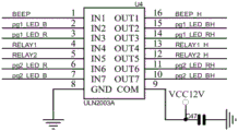
fig. 5 is a schematic diagram of the driving chip of the present invention;
fig. 6 is a schematic circuit diagram of the electronic switch module of the present invention;
fig. 7 is a schematic circuit diagram of the relay fault detection module of the present invention;
FIG. 8 is a schematic circuit diagram of the fuse fault detection module of the present invention;
fig. 9 is a schematic circuit diagram of the current collecting circuit of the present invention;
fig. 10 is a schematic diagram of the voltage sensor of the present invention;
fig. 11 is a schematic circuit diagram of the voltage acquisition circuit of the present invention;
fig. 12 is a schematic circuit diagram of the alarm module of the present invention;
fig. 13 is a schematic circuit diagram of the communication module of the present invention.
The reference numerals are explained below:
10-shell, 101-RFID card reading area, 102-two-dimensional code, 20-MCU control module, 30-RFID reading and writing module, 40-voltage detection module, 50-RTC module, 60-power module, 601-rectification module, 602-DC/DC voltage reduction module, 603-L DO voltage reduction module, 70-charging loop control unit, 701-electronic switch module, 702-fault detection module, 703-current detection module, 80-charging socket, 90-communication module, 100-display module, 1001-digital tube display, 110-L ED indication module, 1101-indication lamp ring, 120-temperature detection module, 130-alarm module, 140-key module, 1401-selection key, 150-cloud platform, 160-client and 170-electric vehicle.
Detailed Description
The present invention will be described in further detail with reference to the accompanying drawings and examples; however, the utility model discloses an electric motor car intelligent charging equipment is not limited to the embodiment.
In an embodiment, please refer to fig. 1 to 2, the present invention relates to an intelligent charging device for an electric vehicle, which comprises a housing 10, a MCU control module 20 is disposed in the housing 10, a RFID read/write module 30, a voltage detection module 40, a RTC module 50, a power module 60 and at least one charging loop control unit 70, the charging loop control unit 70 comprises an electronic switch module 701, a fault detection module 702 and a current detection module 703, the RFID read/write module 30, the voltage detection module 40, the RTC module 50, the electronic switch module 701, the fault detection module 702 and the current detection module 703 are respectively connected to the MCU control module 20, the MCU control module 20 is configured to coordinate operations of the modules, an ac input power is connected to a charging socket 80 through the electronic switch module 701, the electronic switch module 701 is configured to control the ac input power to be connected to or disconnected from the charging socket 80 under the control of the MCU control module 20, the charging socket 80 is disposed on the housing 10, the charging socket 80 has a charging interface (not shown) for accessing a charger of the electric vehicle 170, the RFID read/write module 30 is used for reading RFID card information of a user and identifying user authority and authorizing the user to be charged, the RFID read/write module 30 has an RFID card reading area 101 disposed on the housing 10, the fault detection module 702 is connected with the electronic switch module 701 to detect whether the voltage output of the electronic switch module 701 is normal and feed back the detection result to the MCU control module 20, the current detection module 703 is connected with the electronic switch module 701 to detect the output current of the electronic switch module 701 and feed back the detection result to the MCU control module 20, the voltage detection module 40 is used for detecting the input voltage of the ac input power and feeding back the detection result to the MCU control module 20, the RTC module 50 (RTC: Real-Time Clock) is used for providing current Time information to the MCU control module 20, a power module 60 provides power to the modules.
In this embodiment, the voltage detection module 40 detects an input voltage (i.e., a charging voltage) of the ac input power and feeds back a detection result to the MCU control module 20, the MCU control module 20 compares the received input voltage value with a preset voltage threshold, and when the input voltage of the ac input power is over-voltage or under-voltage, the MCU control module 20 sends a control signal to enable the electronic switch module 701 to disconnect the ac input power from the charging socket 80, so as to terminate charging, prevent damage to a rechargeable battery of the electric vehicle 170, and prolong the service life of the battery; the current detection module 703 detects the output current of the electronic switch module 701 and feeds back the detection result to the MCU control module 20, and the MCU control module 20 compares the received output current value with a preset current threshold, and determines whether an overcurrent or overload occurs during the charging process according to the comparison result to send a control signal to turn off the ac input power supply and the charging socket 80 of the electronic switch module 701 in time. In addition, since the charging current is obviously reduced in the later stage of battery charging, and the charging current is close to zero when the remaining capacity of the battery is close to the rated capacity of the battery, the MCU control module 20 can determine whether the rechargeable battery of the electric vehicle 170 is fully charged according to the output current value fed back by the current detection module 703, and disconnect the ac input power supply and the charging socket 80 when the rechargeable battery is fully charged, thereby preventing the occurrence of overcharge and accelerated battery aging; when the electronic switch module 701 is turned on to connect the ac input power and the charging socket 80, the MCU control module 20 can determine whether the charging socket 80 is in an idle state according to the output current value fed back by the current detection module 703, and turn off the ac input power and the charging socket 80 to prevent the charging socket 80 from being still charged due to the user pulling out the charger in advance.
In this embodiment, the MCU control module 20 calculates the electric energy consumed by the electric vehicle 170 according to the received input voltage value of the ac input power and the output current value of the electronic switch module 701, and when the electric vehicle 170 reaches a preset electric energy threshold (the preset electric energy threshold may be preset by a user), the MCU control module 20 sends a control signal to enable the electronic switch module 701 to disconnect the ac input power from the charging socket 80, so as to limit the charging time.
Referring to fig. 1 to 3, in the present embodiment, the wireless communication system further includes a communication module 90 connected to the MCU control module 20, the communication module 90 is disposed in the housing 10, the MCU control module 20 is in wireless communication with the cloud platform 150 through the communication module 90, the cloud platform 150 is in wireless communication with the client 160 through the mobile network, the two-dimensional code 102 is disposed on the housing 10, and the client 160 establishes wireless communication with the MCU control module 20 through scanning the two-dimensional code 102. The communication module 90 may adopt an NBIOT module, a GPRS module, or a ZIGBEE module, and when the communication module 90 adopts the ZIGBEE module, the ZIGBEE module is in wireless communication connection with the cloud platform 150 through a gateway; the client 160 is an application on a mobile terminal (e.g., a mobile phone, Ipad, etc.). In this embodiment, the communication module 90 adopts an NBIOT module, and the client 160 is a WeChat or Paibao on a mobile phone.
Referring to fig. 1, in the embodiment, the portable charging device further comprises a display module 100, a L ED indication module 110, a temperature detection module 120 and an alarm module 130, wherein the display module 100, the L ED indication module 110, the temperature detection module 120 and the alarm module 130 are respectively connected with the MCU control module 20, specifically, the temperature detection module 120 is disposed in the housing 10 for detecting the temperature inside the housing 10, the temperature detection module 120 comprises a temperature sensor and a temperature acquisition circuit, the temperature sensor is connected with the MCU control module 20 through the temperature acquisition circuit, when the temperature detection module 120 detects that the temperature inside the housing 10 is too high, the MCU control module sends a control signal to cause the electronic switch module 701 to disconnect the ac input power from the charging socket 80 to protect the electric vehicle 170 from dangerous situations, the alarm module 130 is used for sending an alarm signal when the temperature detection module 120 detects that the temperature inside the housing 10 is abnormal, the L indication module 110 is used for indicating the use status of the charging socket 80 and indicating the location of the charging socket 80 at night, where the use status of the charging socket 80 includes, but is not limited to the charging status and the non-charging status, see fig. 2 and 3, L, the ring indicator module 110 includes but the charging indicator module 20 and the display information of the charging ring indicator card number, and the display of the charging socket 80, and the display of the charging indicator card number, the charging indicator.
Referring to fig. 1, in the present embodiment, the present embodiment further includes a key module 140 connected to the MCU control module 20, two charging loop control units 70 (only one charging loop control unit 70 is shown in fig. 1) are disposed in the housing 10, the number of the charging sockets 80 is also two, the two charging sockets 80 are respectively connected to the two charging loop control units 70 in a one-to-one correspondence, and the key module 140 is configured to select one of the two charging loop control units 70 and the corresponding charging socket 80 for charging. Specifically, referring to fig. 2, the key module 140 has two selection keys 1401 disposed on the housing 10, the two selection keys 1401 are disposed corresponding to the two charging sockets 80, and the user can select the corresponding charging socket 80 to charge through the selection keys 1401.
Referring to fig. 1, in the present embodiment, the power module 60 includes a rectifying module 601, a DC/DC voltage-reducing module 602, and an L DO voltage-reducing module 603, which are sequentially connected, an input end of the rectifying module 601 is connected to an ac input power, and the L DO voltage-reducing module 603 can perform linear voltage stabilization on voltage.
In this embodiment, the shell 10 is made of a PC flame retardant material, and the flame retardant rating V0 further reduces the potential safety hazard of fire, the size of the shell 10 is 275mm 106mm 68mm, the charging socket 80 is a national standard 5-hole 10A charging socket 80, and the two-dimensional code 102 is printed on the shell 10. The utility model discloses an each module integration is in shell 10, and whole volume is less, and occupation space is little, but the miniature charging station is established in the narrow and small space of some house or the village in the city of making full use of.
Referring to fig. 4 and 5, in this embodiment, the MCU control module 20 includes a main control chip U1 and a driver chip U4, the main control chip U1 is connected to the alarm modules 130 and L ED indication module 110 and the electronic switch module 701 through a driver chip U4, the model of the main control chip U1 is STM32F030CC which includes 48 pins, corresponding english labels of the pins are shown in fig. 4, the model of the driver chip U4 is U L N2003A which includes 16 pins, corresponding english labels of the pins are shown in fig. 5 in combination with the connection relationship shown in the drawing, in this embodiment, pin 1 of the driver chip U4 in fig. 5 is connected to pin 28 of the main control chip U1 in fig. 4, pin 4 of the driver chip U4 in fig. 5 is connected to pin 25 of the main control chip U1 in fig. 4, pin 5 of the driver chip U4 in fig. 5 is connected to pin 22 of the main control chip U1 in fig. 4, pin 1 in fig. 4 is connected to pin 30 of the main control chip U1 in fig. 4, pin 5 is connected to pin 584, and pin 5 is connected to pin 464 of the key module 20, and pin 464, and the RTC 4611 is connected to the RTC chip 20, the RTC chip 20 is connected to the detection module 20, the RTC 16, the RTC chip 20, the RTC module 20 is connected to detect the RTC 16, and.
In this embodiment, two charging loop control units 70 are disposed in the housing 10, and the principles and components of the two charging loop control units 70 are substantially the same, so fig. 6 to 8 only show the schematic circuit diagrams of each module in one of the charging loop control units 70.
Referring to fig. 6, in the present embodiment, the electronic switch module 701 includes a relay K1 and a fuse F2, a control input terminal of the relay K1 is connected to the MCU control module 20, a live input terminal of the ac input power is connected to a power input terminal of the relay K1, a power output terminal of the relay K1 is connected to a first terminal of the fuse F2, a second terminal of the fuse F2 is connected to a live terminal of the charging socket 80, a neutral input terminal of the ac input power is connected to a neutral terminal of the charging socket 80, and the fuse F2 can perform an output short-circuit protection function.
In this embodiment, the fault detection module 702 includes a relay fault detection module and a fuse fault detection module, an input end of the relay fault detection module is connected to a power output end of the relay K1, an output end of the relay fault detection module is connected to the MCU control module 20, after the MCU control module 20 sends out a control signal to enable the electronic switch module 701 to disconnect the ac input power and the charging socket 80, whether the relay K1 is reliably disconnected from the circuit can be detected by the relay fault detection module, if the relay K1 is not disconnected, the fault detection module can judge that the relay K1 is faulty, an input end of the fuse fault detection module is connected to a second end of the fuse F2, an output end of the fuse fault detection module is connected to the MCU control module 20, when the electronic switch module 701 connects the ac input power and the charging socket 80, whether the fuse F2 is fused or not can be detected by the fuse fault detection module, when the relay K1 or the fuse F367 fails, the MCU control module 20 sends out a control signal to enable the L ED indication module 110 to make a corresponding fault prompt so as to notify maintenance personnel to replace the MCU in time, and the control module 20 can also push the relay K35563268 or the.
Specifically, referring to fig. 7, the relay fault detection module includes a first photocoupler U10, the model of the first photocoupler U10 is PC817, a pin 1 of the first photocoupler U10 in fig. 7 is connected to a pin 6 of the relay K1 in fig. 6 sequentially through a resistor R52 and a resistor R49, and a pin 4 of the first photocoupler U10 in fig. 7 is connected to a pin 29 of the main control chip U1 in fig. 4; referring to fig. 8, the fuse fault detection module includes a second photocoupler U9, the second photocoupler U9 is PC817 in model, a pin 1 of the second photocoupler U9 in fig. 8 is connected to the second end of the fuse F2 in fig. 6 sequentially through a resistor R51 and a resistor R47, and a pin 4 of the second photocoupler U9 in fig. 8 is connected to a pin 30 of the main control chip U1 in fig. 4.
Referring to fig. 6 and 9, in the present embodiment, the current detection module 703 includes a current sensor CT1 and a current collection circuit, a pin 1 of a current sensor CT1 in fig. 6 is connected to a live wire end of the charging socket 80, a pin 2 of a current sensor CT1 in fig. 6 is connected to a second end of the fuse F2 in fig. 6, a pin 3 and a pin 4 of a current sensor CT1 in fig. 6 are connected to an input end of the current collection circuit in fig. 9, and an output end of the current collection circuit in fig. 9 is connected to a pin 15 of the main control chip U1 in fig. 4.
Referring to fig. 10 and 11, in the present embodiment, the voltage detection module 40 includes a voltage sensor PT1 and a voltage acquisition circuit, a pin 1 and a pin 2 of a voltage sensor PT1 in fig. 10 are respectively connected to a live line and a neutral line of an ac input power supply, a pin 3 and a pin 4 of a voltage sensor PT1 in fig. 10 are connected to an input terminal of the voltage acquisition circuit in fig. 11, and an output terminal of the voltage acquisition circuit in fig. 11 is connected to a pin 14 of a main control chip U1 in fig. 4.
Referring to fig. 12, in the present embodiment, the alarm module 130 is an acoustic alarm module 130, the alarm module 130 includes a speaker B1 and a resistor R20, and a pin 2 of a speaker B1 in fig. 12 is connected to a pin 16 of a driver chip U4 in fig. 5 through the resistor R20.
Referring to fig. 13, fig. 13 is a schematic circuit diagram of the communication module 90, and the communication module 90 is connected to the pins 10 to 12 of the main control chip U1 in fig. 4.
The utility model discloses support to sweep sign indicating number dual mode authorization user through RFID card discernment and customer end 160 and charge, it is very convenient to use. When the mobile phone is used for the first time, a user can scan the two-dimensional code 102 on the shell 10 through the client 160 on the mobile phone to enter a user operation interface, account registration is completed in the user operation interface, and the user can view the positions of the surrounding idle charging sockets 80 in the user operation interface.
When the RFID card reader is used, the RFID card is close to the RFID card reading area 101 on the shell 10, when the RFID reading and writing module 30 identifies the RFID card, the corresponding indicator lamp ring 1101 is changed from green to red, the display module 100 displays user information, a user selects the corresponding charging socket 80 through the selection key 1401 to charge the electric vehicle 170, the MCU control module 20 sends out a control signal to enable the electronic switch module 701 to be connected with an alternating current input power supply and the charging socket 80, the charging socket 80 can charge the battery of the electric vehicle 170, and the RFID card can be removed in the charging process; after charging, the user brings the RFID card close to the RFID card reading area 101 again, updates the balance on the card, and simultaneously the display module 100 displays charging information, the MCU control module 20 sends a control signal to enable the electronic switch module 701 to disconnect the ac input power from the charging socket 80, and the indicator lamp ring 1101 turns from red to green.
When a user scans the two-dimensional code 102 on the shell 10 through the client 160 on the mobile phone, the interface of the client 160 automatically jumps to a charging interface, the user can select an idle charging socket 80 on the charging interface to charge the electric vehicle 170 and select the amount of money paid to determine the charging time, after the user pays, the MCU control module 20 sends a control signal to enable the electronic switch module 701 to connect the alternating current input power supply and the charging socket 80, and the charging socket 80 can charge the battery of the electric vehicle 170; during the charging process, the MCU control module 20 uploads the charging information and the state information of the charging socket 80 to the cloud platform 150 through the communication module 90, and the cloud platform 150 sends the charging information and the state information of the charging socket 80 to the client 160, so as to remotely monitor the charging process through the client 160; after the charging is completed, the MCU control module 20 sends a control signal to enable the electronic switch module 701 to disconnect the ac input power from the charging socket 80.
The above-mentioned embodiment is only used for further explaining the utility model discloses an electric motor car intelligence battery charging outfit, nevertheless the utility model discloses do not confine the embodiment to, all be according to the utility model discloses a technical entity is to any simple modification, the equivalent change and the modification of doing of above embodiment, all falls into the utility model discloses technical scheme's protection within range.
Claims (10)
1. An intelligent charging device of an electric vehicle is characterized by comprising a shell, wherein an MCU control module, an RFID read-write module, a voltage detection module, an RTC module, a power supply module and at least one charging loop control unit are arranged in the shell, the charging loop control unit comprises an electronic switch module, a fault detection module and a current detection module, the RFID read-write module, the voltage detection module, the RTC module, the electronic switch module, the fault detection module and the current detection module are respectively connected with the MCU control module, an AC input power supply is connected with a charging socket through the electronic switch module, the charging socket is arranged on the shell, the fault detection module is connected with the electronic switch module to detect whether the voltage output of the electronic switch module is normal or not, the current detection module is connected with the electronic switch module to detect the output current of the electronic switch module, the voltage detection module is used for detecting the input voltage of the alternating current input power supply, and the power supply module supplies power to each module.
2. The intelligent charging equipment for the electric vehicle as claimed in claim 1, further comprising a communication module connected with the MCU control module, wherein the MCU control module is in wireless communication connection with a cloud platform through the communication module, the cloud platform is in wireless communication connection with a client, a two-dimensional code is arranged on the shell, and the client establishes wireless communication connection with the MCU control module through scanning the two-dimensional code.
3. The intelligent charging equipment for the electric vehicle as claimed in claim 1, further comprising a temperature detection module for detecting the temperature inside the housing, wherein the temperature detection module comprises a temperature sensor and a temperature acquisition circuit, and the temperature sensor is connected with the MCU control module through the temperature acquisition circuit.
4. The intelligent charging equipment for the electric vehicle as claimed in claim 3, further comprising an alarm module, wherein the alarm module is connected with the MCU control module.
5. The intelligent charging equipment for the electric vehicle as claimed in claim 1, wherein the electronic switch module comprises a relay and a fuse, a control input end of the relay is connected with the MCU control module, a live wire input end of the alternating current input power supply is connected with a power input end of the relay, a power output end of the relay is connected with a first end of the fuse, and a second end of the fuse is connected with a live wire end of the charging socket.
6. The intelligent charging equipment for electric vehicles according to claim 5, wherein the fault detection module comprises a relay fault detection module and a fuse fault detection module, an input end of the relay fault detection module is connected with a power output end of the relay, an output end of the relay fault detection module is connected with the MCU control module, an input end of the fuse fault detection module is connected with a second end of the fuse, and an output end of the fuse fault detection module is connected with the MCU control module.
7. The intelligent charging device for electric vehicles according to claim 1, further comprising L ED indicating module connected with the MCU control module, wherein the L ED indicating module is used for indicating the use status of the charging socket and/or indicating the position of the charging socket at night.
8. The intelligent charging equipment for the electric vehicle as claimed in claim 1, further comprising a display module connected with the MCU control module, wherein the display module is used for displaying at least one of user information, charging information and equipment failure prompt information.
9. The intelligent charging equipment for the electric vehicle as claimed in claim 1, further comprising a key module connected with the MCU control module, wherein at least two charging loop control units are arranged in the housing, the number of the charging sockets is matched with the number of the charging loop control units, and the key module is used for selecting one of the at least two charging loop control units and the corresponding charging socket for charging.
10. The intelligent charging equipment for the electric vehicle as claimed in claim 1, wherein the power module comprises a rectification module, a DC/DC voltage reduction module and an L DO voltage reduction module which are connected in sequence, and the input end of the rectification module is connected with the AC input power supply.
Priority Applications (1)
| Application Number | Priority Date | Filing Date | Title |
|---|---|---|---|
| CN201921420265.1U CN211075601U (en) | 2019-08-29 | 2019-08-29 | Intelligent charging equipment for electric vehicle |
Applications Claiming Priority (1)
| Application Number | Priority Date | Filing Date | Title |
|---|---|---|---|
| CN201921420265.1U CN211075601U (en) | 2019-08-29 | 2019-08-29 | Intelligent charging equipment for electric vehicle |
Publications (1)
| Publication Number | Publication Date |
|---|---|
| CN211075601U true CN211075601U (en) | 2020-07-24 |
Family
ID=71644355
Family Applications (1)
| Application Number | Title | Priority Date | Filing Date |
|---|---|---|---|
| CN201921420265.1U Active CN211075601U (en) | 2019-08-29 | 2019-08-29 | Intelligent charging equipment for electric vehicle |
Country Status (1)
| Country | Link |
|---|---|
| CN (1) | CN211075601U (en) |
Cited By (2)
| Publication number | Priority date | Publication date | Assignee | Title |
|---|---|---|---|---|
| CN112531813A (en) * | 2020-11-17 | 2021-03-19 | 深圳市易优斯科技有限公司 | Wireless device charger and wireless device charger detection method |
| CN112977121A (en) * | 2021-02-24 | 2021-06-18 | 北京华智网联新能源科技有限公司 | Public charging service management system based on 5G artificial intelligence and Internet of things |
-
2019
- 2019-08-29 CN CN201921420265.1U patent/CN211075601U/en active Active
Cited By (2)
| Publication number | Priority date | Publication date | Assignee | Title |
|---|---|---|---|---|
| CN112531813A (en) * | 2020-11-17 | 2021-03-19 | 深圳市易优斯科技有限公司 | Wireless device charger and wireless device charger detection method |
| CN112977121A (en) * | 2021-02-24 | 2021-06-18 | 北京华智网联新能源科技有限公司 | Public charging service management system based on 5G artificial intelligence and Internet of things |
Similar Documents
| Publication | Publication Date | Title |
|---|---|---|
| WO2018064861A1 (en) | Dual-connector electric car direct current charging pile | |
| CN202817860U (en) | Intelligent portable mobile power supply charger | |
| US9013206B2 (en) | Plug-in electric vehicle supply equipment having a process and device for circuit testing | |
| CN101811446A (en) | Charging cable with controller | |
| KR101821008B1 (en) | Electic automobile recharge apparatus | |
| CN106476650A (en) | Portable charging energy-storing system and its control method | |
| CN107658648A (en) | Charging socket for electric vehicle based on Quick Response Code | |
| CN211075601U (en) | Intelligent charging equipment for electric vehicle | |
| CN111251920A (en) | Integrated charging pile intelligent control system and control method thereof | |
| CN201893777U (en) | Emergency satellite communication box | |
| CN103311984A (en) | Alternating current charging post for electric automobile | |
| KR20110076859A (en) | A remote metering system for the recharge of an electric vehicle | |
| CN107947332B (en) | Vehicle-mounted mobile direct-current emergency power box | |
| CN112977121A (en) | Public charging service management system based on 5G artificial intelligence and Internet of things | |
| CN105490359A (en) | Power supply management apparatus for electric vehicle | |
| CN102170162A (en) | Electric vehicle charger device | |
| CN210109280U (en) | Remote capacity checking system for storage battery of electric direct-current power supply | |
| CN207782458U (en) | A kind of electric vehicle charge control system based on Internet of Things | |
| CN210970734U (en) | Integrated finished automobile direct-current charger | |
| CN207542851U (en) | A kind of charging system with battery charger failure detection and warning function | |
| CN207156958U (en) | direct-current charging post | |
| CN205453253U (en) | Electric automobile power supply management device | |
| CN206416866U (en) | Portable charging energy-storing system | |
| KR20110076858A (en) | A remote metering system for the recharge of an electric vehicle | |
| CN211075565U (en) | Centralized management type intelligent charging system for electric vehicle |
Legal Events
| Date | Code | Title | Description |
|---|---|---|---|
| GR01 | Patent grant | ||
| GR01 | Patent grant |