CN211074491U - Injection mold with secondary injection molding function - Google Patents
Injection mold with secondary injection molding function Download PDFInfo
- Publication number
- CN211074491U CN211074491U CN201921574331.0U CN201921574331U CN211074491U CN 211074491 U CN211074491 U CN 211074491U CN 201921574331 U CN201921574331 U CN 201921574331U CN 211074491 U CN211074491 U CN 211074491U
- Authority
- CN
- China
- Prior art keywords
- mold
- pipe
- base
- feeding pipe
- feeding
- Prior art date
- Legal status (The legal status is an assumption and is not a legal conclusion. Google has not performed a legal analysis and makes no representation as to the accuracy of the status listed.)
- Active
Links
Images

Landscapes
- Moulds For Moulding Plastics Or The Like (AREA)
Abstract
The utility model discloses an injection mold with secondary function of moulding plastics relates to the injection mold field, can not the secondary problem of moulding plastics to current injection mold, now proposes following scheme, and it includes the base, be connected with two pole settings on the base perpendicularly, and the pole setting sets up the both ends at the base respectively, the one end of keeping away from the base in the pole setting is passed through the diaphragm and is connected, be provided with mould and bed die on the base, and bed die fixed mounting is on the surface of base, go up the mould activity and set up the surface at the bed die, and both sides difference fixedly connected with push pedal, the mould groove has been seted up between last mould and the bed die, the material chamber has been seted up in the last mould, and the material chamber sets up the top in the mould groove. The utility model discloses a diameter that sets up the pan feeding pipe is greater than the diameter that leads to the material pipe, consequently can realize the intraductal pan feeding intracavity of raw materials accessible pan feeding that the secondary was moulded plastics, this device novel structure, the design is unique, and is rational in infrastructure, is fit for promoting.
Description
Technical Field
The utility model relates to an injection mold field especially relates to an injection mold with secondary function of moulding plastics.
Background
An injection mold is a tool for producing plastic products; and is also a tool for giving the plastic product complete structure and accurate dimension. Injection molding is a process used to mass produce parts of some complex shapes. Specifically, the plastic melted by heating is injected into a mold cavity from an injection molding machine at high pressure, and a formed product is obtained after cooling and solidification. The structure of the mold may vary widely depending on the kind and properties of the plastic, the shape and structure of the plastic product, and the type of the injection molding machine, but the basic structure is uniform.
The existing injection mold only has one injection port and cannot perform secondary injection molding, so that an injection mold with a secondary injection molding function is urgently needed to solve the problems.
Disclosure of Invention
The utility model provides a pair of injection mold with secondary function of moulding plastics has solved injection mold and can not the secondary problem of moulding plastics.
In order to achieve the above purpose, the utility model adopts the following technical scheme:
an injection mold with a secondary injection molding function comprises a base, wherein two vertical rods are vertically connected to the base and are respectively arranged at two ends of the base, one ends of the vertical rods, far away from the base, are connected through a transverse plate, an upper mold and a lower mold are arranged on the base and are fixedly arranged on the surface of the base, the upper mold is movably arranged on the surface of the lower mold, push plates are respectively and fixedly connected to two sides of the upper mold, a mold groove is formed between the upper mold and the lower mold, a material cavity is formed in the upper mold and is arranged above the mold groove, the material cavity is communicated with the mold groove through a main feeding pipeline, secondary feeding pipelines are respectively arranged at two sides of the main feeding pipeline, the secondary feeding pipelines are arranged in parallel to the main feeding pipeline and are communicated with the mold groove and the material cavity, and a feeding pipe II is connected to the surface of the upper mold, and a first feeding pipe is movably arranged in the second feeding pipe, a material passing pipe is vertically arranged on the surface of the upper die, movably penetrates through the upper die and is inserted into the main feeding pipeline.
Preferably, the first inlet pipe is movably sleeved at one end, which is not inserted into the upper die, of the material passing pipe, a sealing ring is arranged on the outer side of the material passing pipe, and a pulling plate is fixedly connected to one end, which is far away from the material passing pipe, of the first inlet pipe.
Preferably, a feeding pipe is arranged in the upper die, the material passing pipe movably penetrates through the feeding pipe, the feeding pipe two is connected to the pipe opening of the feeding pipe, and the diameter of the feeding pipe is larger than that of the pipe opening of the material passing pipe.
Preferably, both ends of the pulling plate are fixedly connected with a pressing rod respectively, one end of the pressing rod movably penetrates through the upper die and extends into the material cavity, one end of the pressing rod inserted into the material cavity is fixedly connected with a sealing plug, and the sealing plug is arranged at a pipe orifice of the secondary feeding pipeline.
Preferably, the transverse plate is connected with the push plates on two sides of the upper die through hydraulic rods respectively.
Preferably, the upper die is movably connected with the transverse plate through a limiting rod.
The utility model has the advantages that:
1. the main feeding pipeline and the secondary feeding pipeline are arranged on the die groove, so that the device has the function of secondary feeding, and the pipelines of secondary feeding and primary feeding are distinguished, thereby being more convenient;
2. the utility model discloses a diameter that sets up the pan feeding pipe is greater than the diameter that leads to the material pipe, consequently can realize the intraductal pan feeding intracavity of raw materials accessible pan feeding that the secondary was moulded plastics, this device novel structure, the design is unique, and is rational in infrastructure, is fit for promoting.
Drawings
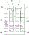
Fig. 1 is a schematic structural diagram of the present invention.
Fig. 2 is an enlarged view of a portion a in fig. 1.
Reference numbers in the figures: the device comprises a base 1, upright rods 2, a transverse plate 3, a lower die 4, an upper die 5, a hydraulic rod 6, a push plate 7, a die groove 8, a pull plate 9, a first feeding pipe 10, a second feeding pipe 11, a compression rod 12, a sealing plug 13, a main feeding pipeline 14, a secondary feeding pipeline 15, a material cavity 16 and a material passing pipe 17.
Detailed Description
The technical solutions in the embodiments of the present invention will be described clearly and completely with reference to the accompanying drawings in the embodiments of the present invention, and it is obvious that the described embodiments are only some embodiments of the present invention, not all embodiments.
Referring to fig. 1-2, an injection mold with secondary injection molding function comprises a base 1, two upright rods 2 are vertically connected to the base 1, the upright rods 2 are respectively arranged at two ends of the base 1, one ends of the upright rods 2 far away from the base 1 are connected through a transverse plate 3, an upper mold 5 and a lower mold 4 are arranged on the base 1, the lower mold 4 is fixedly arranged on the surface of the base 1, the upper mold 5 is movably arranged on the surface of the lower mold 4, push plates 7 are respectively and fixedly connected at two sides, a mold groove 8 is arranged between the upper mold 5 and the lower mold 4, a material cavity 16 is arranged in the upper mold 5, the material cavity 16 is arranged above the mold groove 8, the material cavity 16 is communicated with the mold groove 8 through a main feed pipe 14, secondary feed pipes 15 are respectively arranged at two sides of the main feed pipe 14, the secondary feed pipes 15 are arranged in parallel to the main feed pipe 14 and are communicated with the mold groove 8 and the material cavity 16, the surface of the upper die 5 is connected with a feeding pipe II 11, a feeding pipe I10 is movably arranged in the feeding pipe II 11, a material passing pipe 17 is vertically arranged on the surface of the upper die 5, the material passing pipe 17 movably penetrates through the upper die 5 and is inserted into a main feeding pipeline 14, the feeding pipe I10 is movably sleeved at one end of the material passing pipe 17 which is not inserted into the upper die 5, a sealing ring is arranged on the outer side of the material passing pipe 17, a pulling plate 9 is fixedly connected to one end of the feeding pipe I10 far away from the material passing pipe 17, a feeding pipe is arranged in the upper die 5, the material passing pipe 17 movably penetrates through the feeding pipe, the feeding pipe II 11 is connected to the pipe opening of the feeding pipe, the diameter of the feeding pipe is larger than that of the material passing pipe 17, two ends of the pulling plate 9 are respectively and fixedly connected with a pressing rod 12, one end of the pressing rod 12 movably penetrates through the upper die 5 and, and the sealing plug 13 is arranged at the pipe orifice of the secondary feeding pipeline 15, the transverse plate 3 and the push plates 7 at the two sides of the upper die 5 are respectively connected through the hydraulic rod 6, and the upper die 5 and the transverse plate 3 are movably connected through the limiting rod.
The working principle is as follows: when the device is used, the hydraulic rod 6 is started, the position between the upper die 5 and the lower die 4 is adjusted, when the device is used for injection molding for the first time, the pulling plate 9 is pressed downwards, the sealing plug 13 enters the secondary feeding pipeline 15, the first feeding pipe 10 penetrates the surface of the pulling plate 9, then raw materials are added into the first feeding pipe 10, then the raw materials enter the main material pipeline 14 through the material passing pipe 17, the first injection molding is completed, if the secondary injection molding is needed, the pulling plate 9 is pulled upwards, the first feeding pipe 10 is far away from the pipe orifice of the second feeding pipe 11, the pressing rod 12 drives the sealing plug 13 to be far away from the pipe orifice of the secondary feeding pipeline 15, the injection molding is performed into the second feeding pipe 11, the diameter of the feeding pipe is larger than that of the material passing pipe 17, therefore, the injection molded raw materials enter the material cavity 16 through the feeding pipe, and enter the.
The above, only be the concrete implementation of the preferred embodiment of the present invention, but the protection scope of the present invention is not limited thereto, and any person skilled in the art is in the technical scope of the present invention, according to the technical solution of the present invention and the utility model, the concept of which is equivalent to replace or change, should be covered within the protection scope of the present invention.
Claims (6)
1. An injection mold with secondary injection molding function comprises a base (1) and is characterized in that two upright rods (2) are vertically connected to the base (1), the upright rods (2) are respectively arranged at two ends of the base (1), one ends, far away from the base (1), of the upright rods (2) are connected through a transverse plate (3), an upper mold (5) and a lower mold (4) are arranged on the base (1), the lower mold (4) is fixedly arranged on the surface of the base (1), the upper mold (5) is movably arranged on the surface of the lower mold (4), two sides of the upper mold are respectively and fixedly connected with a push plate (7), a mold groove (8) is formed between the upper mold (5) and the lower mold (4), a material cavity (16) is formed in the upper mold (5), the material cavity (16) is arranged above the mold groove (8), and the material cavity (16) is communicated with the mold groove (8) through a main feeding pipeline (14), and the two sides of the main feeding pipeline (14) are respectively provided with a secondary feeding pipeline (15), the secondary feeding pipeline (15) and the main feeding pipeline (14) are arranged in parallel and communicated with the die groove (8) and the material cavity (16), the surface of the upper die (5) is connected with a second feeding pipe (11), a first feeding pipe (10) is movably arranged in the second feeding pipe (11), a material passing pipe (17) is vertically arranged on the surface of the upper die (5), and the material passing pipe (17) movably penetrates through the upper die (5) and is inserted into the main feeding pipeline (14).
2. The injection mold with the secondary injection molding function according to claim 1, wherein the first feeding pipe (10) is movably sleeved at one end of the first feeding pipe (17) which is not inserted into the upper mold (5), a sealing ring is arranged on the outer side of the first feeding pipe (17), and a pulling plate (9) is fixedly connected to one end, far away from the first feeding pipe (10), of the first feeding pipe (10).
3. The injection mold with the secondary injection molding function according to claim 1, wherein a feeding pipe is arranged in the upper mold (5), a material passing pipe (17) movably penetrates through the feeding pipe, the feeding pipe II (11) is connected to a pipe opening of the feeding pipe, and the diameter of the feeding pipe is larger than that of the pipe opening of the material passing pipe (17).
4. An injection mold with a secondary injection molding function according to claim 2, wherein two ends of the pulling plate (9) are fixedly connected with a pressing rod (12) respectively, one end of the pressing rod (12) movably penetrates through the upper mold (5) and extends into the material cavity (16), one end of the pressing rod (12) inserted into the material cavity (16) is fixedly connected with a sealing plug (13), and the sealing plug (13) is arranged at the pipe orifice of the secondary feeding pipeline (15).
5. An injection mold with secondary injection function according to claim 1, characterized in that the transverse plate (3) and the push plates (7) at both sides of the upper mold (5) are connected through hydraulic rods (6).
6. An injection mold with secondary injection molding function according to claim 1, characterized in that the upper mold (5) is movably connected with the transverse plate (3) through a limiting rod.
Priority Applications (1)
| Application Number | Priority Date | Filing Date | Title |
|---|---|---|---|
| CN201921574331.0U CN211074491U (en) | 2019-09-21 | 2019-09-21 | Injection mold with secondary injection molding function |
Applications Claiming Priority (1)
| Application Number | Priority Date | Filing Date | Title |
|---|---|---|---|
| CN201921574331.0U CN211074491U (en) | 2019-09-21 | 2019-09-21 | Injection mold with secondary injection molding function |
Publications (1)
| Publication Number | Publication Date |
|---|---|
| CN211074491U true CN211074491U (en) | 2020-07-24 |
Family
ID=71641088
Family Applications (1)
| Application Number | Title | Priority Date | Filing Date |
|---|---|---|---|
| CN201921574331.0U Active CN211074491U (en) | 2019-09-21 | 2019-09-21 | Injection mold with secondary injection molding function |
Country Status (1)
| Country | Link |
|---|---|
| CN (1) | CN211074491U (en) |
-
2019
- 2019-09-21 CN CN201921574331.0U patent/CN211074491U/en active Active
Similar Documents
| Publication | Publication Date | Title |
|---|---|---|
| CN208359338U (en) | A kind of injection mold of easy mold release | |
| CN214491490U (en) | Medical catheter assembly injection mold | |
| CN211074491U (en) | Injection mold with secondary injection molding function | |
| CN203317628U (en) | Vertical organic glass casting mould | |
| CN211566844U (en) | Injection mold convenient to open mold | |
| CN210679511U (en) | Injection mold for household appliance charger shell | |
| CN213733209U (en) | Injection mold structure suitable for accurate small-size plastics toy | |
| CN213593513U (en) | Temperature controller shell injection mold | |
| CN210999852U (en) | Plastic foam mould convenient to drawing of patterns | |
| CN208881077U (en) | A kind of sealing ring mould with heating function | |
| CN210590330U (en) | Injection molding mold of integral type lamp body | |
| CN212826596U (en) | Injection mold convenient to demold | |
| CN216400328U (en) | Novel double-colored moulding plastics device | |
| CN216373156U (en) | Strapping tape die | |
| CN211251164U (en) | Novel runner separation mold of injection molding mold | |
| CN109278263A (en) | A kind of embedding and injection molding device of automobile taillight lampshade | |
| CN216267226U (en) | Injection mold of foot cup base | |
| CN212168955U (en) | Inner diameter shaping mold structure of circular open type metal injection molding product | |
| CN219543947U (en) | Injection molding machine | |
| CN220464646U (en) | Forming precision plastic part die | |
| CN217293202U (en) | Injection mold with secondary injection molding function | |
| CN211251178U (en) | Gear injection mold | |
| CN219191147U (en) | Injection mold for thick-wall shell part | |
| CN209095939U (en) | A kind of embedding and injection molding device of automobile taillight lampshade | |
| CN212097305U (en) | Combined injection mold |
Legal Events
| Date | Code | Title | Description |
|---|---|---|---|
| GR01 | Patent grant | ||
| GR01 | Patent grant |