CN211054302U - Point-feeding cold runner injection mold - Google Patents
Point-feeding cold runner injection mold Download PDFInfo
- Publication number
- CN211054302U CN211054302U CN201922000302.XU CN201922000302U CN211054302U CN 211054302 U CN211054302 U CN 211054302U CN 201922000302 U CN201922000302 U CN 201922000302U CN 211054302 U CN211054302 U CN 211054302U
- Authority
- CN
- China
- Prior art keywords
- plate
- runner
- pull rod
- injection mold
- upper die
- Prior art date
- Legal status (The legal status is an assumption and is not a legal conclusion. Google has not performed a legal analysis and makes no representation as to the accuracy of the status listed.)
- Active
Links
Images


Abstract
The utility model provides a point advances gluey cold runner injection mold, including last mould assembly and lower mould assembly, last mould assembly includes cope match-plate pattern, mouth of a river board and at least one runner board, the mouth of a river board sets up in the top of cope match-plate pattern, each runner board inlays to be established in the mouth of a river board, be equipped with into jiao kou and a plurality of first runner with advancing the jiao kou intercommunication on each runner board, be equipped with the mould benevolence and the second runner that corresponds with first runner on the cope match-plate pattern, be equipped with little pull rod between cope match-plate pattern and the mouth of a river board, the lower extreme of little pull rod is fixed on the cope match-plate pattern, little pull rod reduces gradually from top to bottom in cross-section area, be equipped with the spacing groove on the mouth of a river board, the upper end of little pull rod sets up in the spacing groove, there is first distance between the tank bottom surface of spacing groove and the up end of little pull rod, lower mould assembly includes lower bolster and ejector, a plurality of cavities are formed between the lower die core and the upper die core, the cavities are communicated with the second flow channel, and the ejector rods are located below the cavities.
Description
Technical Field
The utility model relates to an injection mold technical field especially relates to a point advances gluey cold runner injection mold.
Background
With the increasing requirements of people on the appearance of various living and industrial products and the appearance of various plastic products, the appearance conditions naturally become important factors for evaluating the product appearance, wherein the positions of gates, gate marks, welding lines and the like of the products become one of factors influencing the acceptance of the products.
The mold is an indispensable important tool in injection molding, and the injection molding is a processing method for injecting hot-melt plastic materials into a closed cavity with a required shape in the mold at a high speed, opening the mold to eject out a solidified plastic product after the plastic materials are cooled and solidified, so as to obtain a molded product. The injection molding processing method has the characteristics of low molding cost, short molding period, simple molding process, easiness in molding of plastic products with complex shapes and the like, so that the injection molding processing method is widely applied to the field of plastic products.
However, the existing point-glue-feeding cold runner injection mold adopts a traditional point-glue-feeding mode, after the mold is opened in injection molding, a waste material head cannot automatically fall off, the waste material head must be removed manually or by a mechanical arm, the waste material head is prone to falling and is not clean, the phenomenon of material head die pressing occurs when an upper mold and a lower mold of the mold are closed after long-time use, the production cannot be carried out after the die pressing, the mold needs to be repaired by a machine, and the great problem is brought to normal production. Meanwhile, the glue inlet point is positioned at the center of the outer side surface of the product, more or less injection molding traces are left on the appearance of the product, and the attractiveness of the product is directly influenced.
SUMMERY OF THE UTILITY MODEL
The utility model aims at solving the problem that the waste material head can not automatically drop after the injection molding die sinking that exists among the prior art, and the provided point advances gluey cold runner injection mold.
In order to achieve the above purpose, the utility model adopts the following technical scheme: a point glue feeding cold runner injection mold comprises an upper mold assembly and a lower mold assembly, wherein the upper mold assembly comprises an upper mold plate, a water gap plate and at least one runner plate, the water gap plate is arranged above the upper mold plate, each runner plate is embedded in the water gap plate, each runner plate is provided with a glue feeding port and a plurality of first runners, the plurality of first runners are respectively communicated with the glue feeding ports, the upper mold plate is provided with an upper mold core and second runners corresponding to the first runners, the second runners are communicated with the first runners, a small pull rod is arranged between the upper mold plate and the water gap plate, the lower end of the small pull rod is fixed on the upper mold plate, the sectional area of the small pull rod is gradually reduced from top to bottom, the water gap plate is provided with a limiting groove, the upper end of the small pull rod is arranged in the limiting groove, a first distance exists between the upper end face of the small pull rod and the bottom face of the limiting groove, the lower mold assembly comprises a lower mold plate and an ejector rod, a mold locking buckle is, the lower die plate is provided with a lower die core, a plurality of cavities are formed between the lower die core and the upper die core, the cavities are communicated with the second flow channel, and the ejector rod is positioned below the cavities.
Preferably, the lower link includes fixed part and movable part, and the fixed part is fixed on the cope match-plate pattern, and the movable part includes stopper and carriage release lever, and the stopper is connected with the carriage release lever, and the carriage release lever setting is in the inside of fixed part and movably connected with the fixed part, and the stopper setting is at the spacing inslot.
Preferably, a plurality of first flow channels communicated with the glue inlet are uniformly arranged around the glue inlet. Furthermore, the glue inlets correspond to the cavities one by one. Furthermore, the glue inlet is positioned right above the center point of the cavity.
Preferably, the cross-sectional area of the second flow channel decreases from top to bottom.
Preferably, the injection mold further comprises guide posts which are uniformly arranged at four corners of the injection mold.
Preferably, the first distance is not less than the height of the second flow channel.
Compared with the prior art, the beneficial effects of the utility model are that: the mold locking buckle is arranged between the upper mold plate and the lower mold plate, and the small pull rod is arranged between the upper mold plate and the water gap plate, so that the runner plate and the water gap plate are separated from the upper mold plate firstly in the mold opening process, the waste head generated in the injection molding is automatically separated from the upper mold plate, the action of a mechanical arm or manually grabbing the waste head is omitted, and the time and the labor are saved; through setting up a plurality ofly and advancing the first runner of jiao kou intercommunication and with the second runner of first runner intercommunication, improved the injecting glue speed to the production efficiency of product has been improved.
Drawings
Fig. 1 is a schematic structural view of a point-feeding cold runner injection mold according to an embodiment of the present invention;
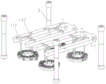
FIG. 2 is a schematic structural view of the small tie rod of FIG. 1;
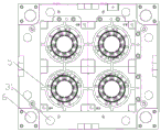
FIG. 3 is a schematic view of the mold cavity of FIG. 1;
fig. 4 is a schematic structural view of the flow channel of fig. 1.
Detailed Description
In order to further understand the objects, structures, features and functions of the present invention, the following embodiments are described in detail.
Referring to fig. 1 to 4, the present invention provides a point-feeding cold runner injection mold, which includes an upper mold assembly 1 and a lower mold assembly 2.
The upper die assembly 1 comprises an upper die plate 11, a water gap plate 12 and at least one runner plate 13, the water gap plate 12 is arranged above the upper die plate 11, each runner plate 13 is embedded in the water gap plate 12, each runner plate 13 is provided with a glue inlet 131 and a plurality of first runners 132, the plurality of first runners 132 are respectively communicated with the glue inlets, the upper die plate 11 is provided with an upper die core 111 and second runners 112 corresponding to the first runners 132, the second runners 112 are communicated with the first runners 132, a small pull rod 3 is arranged between the upper die plate 11 and the water gap plate 12, the lower end of the small pull rod 3 is fixed on the upper die plate 11, the sectional area of the small pull rod 3 is gradually reduced from top to bottom, the water gap plate 12 is provided with a limiting groove 121, the upper end of the small pull rod 3 is arranged in the limiting groove 121, and a first distance d exists between the upper end face of the small pull rod 3 and the groove bottom face of the limiting groove 121. In a preferred embodiment, the small pull rod 3 includes a fixed portion 31 and a movable portion 32, the fixed portion 31 is fixed on the upper plate 11, the movable portion 32 includes a stopper 321 and a moving rod 322, the stopper 321 is connected with the moving rod 322, the moving rod 322 is disposed inside the fixed portion 31 and movably connected with the fixed portion 31, and the stopper 321 is disposed in the stopper groove 121 to increase a moving distance of the nozzle plate 12 with respect to the upper plate 11.
The lower die assembly 2 comprises a lower die plate 21 and ejector rods 22, a die locking buckle 4 is arranged between the upper die plate 11 and the lower die plate 21, a lower die core 211 is arranged on the lower die plate 21, a plurality of cavities 5 are formed between the lower die core 211 and the upper die core 111, the cavities 5 are communicated with the second flow channel 112, and the ejector rods 22 are located below the cavities 5. The mold locking buckle 4 is used for fixing the upper template 11 and the lower template 21, so that the upper template 11 and the lower template 21 can not be opened at the first time, and the mold is prevented from moving. The mold lock 4 may be any mold lock known in the art.
Preferably, a plurality of first flow channels 132 communicated with the glue inlet 131 are uniformly arranged around the glue inlet 131. Further, the glue inlets 131 correspond to the cavities 5 one by one, as shown in fig. 4, the upper die assembly 1 includes a plurality of runner plates 13, each runner plate 13 is provided with a plurality of glue inlets 131, the second runner 112 corresponding to the first runner 132 communicated with the glue inlets 131 is communicated with the cavity 5 corresponding to the glue inlet 131, the upper die assembly 1 may also include a plurality of runner plates 13, each runner plate 13 is provided with one glue inlet 131, the second runner 112 corresponding to the first runner 132 communicated with the glue inlet 131 is communicated with the cavity 5 corresponding to the glue inlet 131, the upper die assembly 1 may also include one runner plate 13, the runner plate 13 is provided with a plurality of glue inlets 131, and the second runner 112 corresponding to the first runner 132 communicated with the glue inlet 131 is communicated with the cavity 5 corresponding to the glue inlet 131, which can both improve the efficiency of product production. Furthermore, the glue inlet 131 is located right above the center point of the cavity 5, so that the cavity 5 can be filled with glue uniformly.
Preferably, the second flow passage 112 has a gradually decreasing cross-sectional area from top to bottom to facilitate the extraction of the scrap head.
Preferably, the injection mold further comprises guide posts 6, and the guide posts 6 are uniformly arranged at four corners of the injection mold to guide the upper template 11 and the lower template 21 to be combined in a correct position.
Preferably, the first distance d is not less than the height of the second runner 112 to ensure that the slug can be completely extracted from the upper die plate.
The mold opening process comprises: under the effect of mode locking buckle 4, nozzle plate 12 and runner plate 13 separate with cope match-plate pattern 11 earlier to the waste material head that produces when will moulding plastics is taken out from the cope match-plate pattern, when stopper 321 of little pull rod 3 and the tank bottom surface contact of spacing groove 121, little pull rod 3 drives cope match-plate pattern 11 and lower bolster 21 separation, and later ejector pin 22 upwards drops the product top.
The utility model discloses a point advances gluey cold runner injection mold, through setting up the mode locking buckle between cope match-plate pattern and lower bolster, set up little pull rod between cope match-plate pattern and nozzle plate, make runner plate and nozzle plate separate with the cope match-plate pattern earlier in the die sinking process, thereby realize that the scrap head that produces comes off from the cope match-plate pattern by oneself during the injection molding, saved the action that the manipulator or manual work snatched the scrap head, save time and economize the manual work; through setting up a plurality ofly and advancing the first runner of jiao kou intercommunication and with the second runner of first runner intercommunication, improved the injecting glue speed to the production efficiency of product has been improved.
The present invention has been described in relation to the above embodiments, which are only examples for implementing the present invention. It should be noted that the disclosed embodiments do not limit the scope of the invention. On the contrary, all changes and modifications which do not depart from the spirit and scope of the present invention are deemed to fall within the scope of the present invention.
Claims (8)
1. A point-feeding cold runner injection mold is characterized by comprising an upper mold assembly and a lower mold assembly;
the upper die assembly comprises an upper die plate, a water gap plate and at least one runner plate, the water gap plate is arranged above the upper die plate, each runner plate is embedded in the water gap plate, each runner plate is provided with a glue inlet and a plurality of first runners, the plurality of first runners are respectively communicated with the glue inlet, the upper die plate is provided with an upper die core and a second runner corresponding to the first runners, the second runners are communicated with the first runners, a small pull rod is arranged between the upper die plate and the water gap plate, the lower end of the small pull rod is fixed on the upper die plate, the sectional area of the small pull rod is gradually reduced from top to bottom, the water gap plate is provided with a limiting groove, the upper end of the small pull rod is arranged in the limiting groove, and a first distance exists between the upper end face of the small pull rod and the groove bottom face of the limiting groove;
the lower die assembly comprises a lower die plate and an ejector rod, a die locking buckle is arranged between the upper die plate and the lower die plate, a lower die core is arranged on the lower die plate, a plurality of cavities are formed between the lower die core and the upper die core, the cavities are communicated with the second flow channel, and the ejector rod is located below the cavities.
2. The spot-feeding cold runner injection mold according to claim 1, wherein the small pull rod comprises a fixed portion and a movable portion, the fixed portion is fixed on the upper mold plate, the movable portion comprises a limiting block and a moving rod, the limiting block is connected with the moving rod, the moving rod is arranged inside the fixed portion and movably connected with the fixed portion, and the limiting block is arranged in the limiting groove.
3. The spot glue feeding cold runner injection mold according to claim 1, wherein a plurality of first runners communicated with the glue feeding port are uniformly arranged around the glue feeding port.
4. The spot glue feeding cold runner injection mold according to claim 3, wherein the glue feeding ports correspond to the cavities one to one.
5. The spot glue cold runner injection mold of claim 4, wherein the glue inlet is located directly above the center point of the cavity.
6. The spot-feeding cold runner injection mold of claim 1, wherein the cross-sectional area of the second runner is gradually reduced from top to bottom.
7. The spot-feeding cold runner injection mold of claim 1, further comprising guide posts uniformly arranged at four corners of the injection mold.
8. The spot-feed cold runner injection mold of claim 1, wherein said first distance is not less than a height of said second runner.
Priority Applications (1)
| Application Number | Priority Date | Filing Date | Title |
|---|---|---|---|
| CN201922000302.XU CN211054302U (en) | 2019-11-19 | 2019-11-19 | Point-feeding cold runner injection mold |
Applications Claiming Priority (1)
| Application Number | Priority Date | Filing Date | Title |
|---|---|---|---|
| CN201922000302.XU CN211054302U (en) | 2019-11-19 | 2019-11-19 | Point-feeding cold runner injection mold |
Publications (1)
| Publication Number | Publication Date |
|---|---|
| CN211054302U true CN211054302U (en) | 2020-07-21 |
Family
ID=71590086
Family Applications (1)
| Application Number | Title | Priority Date | Filing Date |
|---|---|---|---|
| CN201922000302.XU Active CN211054302U (en) | 2019-11-19 | 2019-11-19 | Point-feeding cold runner injection mold |
Country Status (1)
| Country | Link |
|---|---|
| CN (1) | CN211054302U (en) |
-
2019
- 2019-11-19 CN CN201922000302.XU patent/CN211054302U/en active Active
Similar Documents
| Publication | Publication Date | Title |
|---|---|---|
| CN108407231A (en) | A kind of cylinder ejector side action sliders component injection mold | |
| CN214188239U (en) | A high-efficient injection mold for dust catcher hose connection head | |
| CN105415588A (en) | Injection molding process and mold for remote controllers | |
| CN209937577U (en) | Automatic take off stub bar three-plate mold | |
| CN205033505U (en) | Three -plate mold structure | |
| CN211054302U (en) | Point-feeding cold runner injection mold | |
| CN207448964U (en) | A kind of baroceptor shell injection mold | |
| CN216032158U (en) | Plastic injection chair mold with shear-free gate mechanism | |
| CN212795716U (en) | Oblique ejection die | |
| CN202016173U (en) | Three-plate mould | |
| CN209320217U (en) | A kind of three-level ejecting mechanism of double-shot moulding mould | |
| CN212194039U (en) | Ox horn advances gluey injection mold runner structure | |
| CN212147408U (en) | Injection mold of V type thin wall injection molding | |
| CN209699751U (en) | Teacup lid injecting mechanism with taper pin side core-pulling mechanism | |
| CN206357577U (en) | Core-pulling mechanism under a kind of handle injection mold diclinic side of duplicator | |
| CN213891066U (en) | Fan-shaped pouring gate reverse pouring mechanism of large-sized automobile door panel die | |
| CN219338422U (en) | Automatic demoulding mould structure of slider with angle | |
| CN219028346U (en) | Upper and lower cover mould | |
| CN211307272U (en) | Ox horn automatic break glue inlet structure | |
| CN218948344U (en) | Front mold insert shrinking and taking-up mechanism of injection mold | |
| CN211640783U (en) | Precise injection mold | |
| CN215550616U (en) | Injection mold with reversely arranged mold core | |
| CN219563987U (en) | Injection molding mold core of camera cover | |
| CN214111254U (en) | Split stacking demoulding mechanism of light truck rubber-coated plate injection mould | |
| CN216708208U (en) | Injection mold |
Legal Events
| Date | Code | Title | Description |
|---|---|---|---|
| GR01 | Patent grant | ||
| GR01 | Patent grant |