CN211052131U - Weaving machine weaving dirt collection device - Google Patents
Weaving machine weaving dirt collection device Download PDFInfo
- Publication number
- CN211052131U CN211052131U CN201921575749.3U CN201921575749U CN211052131U CN 211052131 U CN211052131 U CN 211052131U CN 201921575749 U CN201921575749 U CN 201921575749U CN 211052131 U CN211052131 U CN 211052131U
- Authority
- CN
- China
- Prior art keywords
- fixedly connected
- dust
- dust collecting
- bounding wall
- textile machine
- Prior art date
- Legal status (The legal status is an assumption and is not a legal conclusion. Google has not performed a legal analysis and makes no representation as to the accuracy of the status listed.)
- Expired - Fee Related
Links
Images


Landscapes
- Auxiliary Weaving Apparatuses, Weavers' Tools, And Shuttles (AREA)
- Preliminary Treatment Of Fibers (AREA)
Abstract
The utility model discloses a textile dust collecting device of a textile machine, which belongs to the field of textile machines, and comprises a frame, the frame comprises a pair of side frames and a main frame fixedly connected between the side frames, the lower end of the side frame is fixedly connected with a pair of supporting legs, a coaming is connected between the two pairs of supporting legs, the lower end middle part of the coaming is fixedly connected with a dust collector, one end of the dust collector is fixedly connected with a dust collecting pipe, the dust collecting pipe penetrates through the side wall of the coaming and extends to the upper side of the coaming, the other end of the dust collector is fixedly connected with a dust outlet pipe, the outer end of the dust outlet pipe is in threaded connection with a dust collecting bag, the outer side of the dust collecting pipe is provided with a mesh enclosure, the mesh enclosure is connected with the coaming, the upper end of the mesh enclosure is provided with a scraping rod, the lower end middle part of the main, and can filter cotton threads in dust.
Description
Technical Field
The utility model relates to a weaving machine field, more specifically say, relate to a weaving machine weaving dirt collection device.
Background
The textile machines are also called textile machines, weaving machines, cotton spinning machines and the like, and the ancient textile machines are weaving machines driven by manpower. The textile machine is a general name of tools for processing raw materials such as threads, silks, hemp and the like into threads and then weaving the threads into cloth, such as a spinning drop, a spinning wheel, a spindle and a pedal loom, as well as a modern mechanical loom, a modern numerical control automatic loom and the like, and the development of the textile process flow and equipment at all times is designed according to the textile raw materials, so the raw materials have an important position in the textile technology.
In the current life, the dust on the weaving machine is generally manually wiped, some dust particles adsorbed on the machine body and the weaving cotton threads are not easy to be completely cleaned, and the dust particles and the weaving cotton threads cannot be well separated when being cleaned.
SUMMERY OF THE UTILITY MODEL
1. Technical problem to be solved
To the problem that exists among the prior art, the utility model aims to provide a weaving machine weaving dirt collection device, it can realize being convenient for collect the dust of collecting the money on the weaving machine, and can filter the cotton thread in the dust.
2. Technical scheme
In order to solve the above problems, the utility model adopts the following technical proposal.
A textile machine textile dust collecting device comprises a frame, the frame comprises a pair of side frames and a main frame fixedly connected between the side frames, the lower end of the side frame is fixedly connected with a pair of supporting legs, a coaming is connected between the two pairs of supporting legs, the middle part of the lower end of the coaming is fixedly connected with a dust collector, one end of the dust collector is fixedly connected with a dust collection pipe, the dust suction pipe penetrates through the side wall of the enclosing plate and extends to the upper side of the enclosing plate, the other end of the dust suction machine is fixedly connected with a dust outlet pipe, the outer end of the dust outlet pipe is connected with a dust collection bag in a threaded manner, the outer side of the dust collection pipe is provided with a mesh enclosure, the net cover is connected with the surrounding plate, the upper end of the net cover is provided with a scraping rod, the middle part of the lower end of the main frame is fixedly connected with a motor, the rotating end of the motor is fixedly connected with the scraping rod, the dust collecting device can collect dust accumulated on the textile machine conveniently and filter cotton threads in the dust.
Furthermore, the upper end of the scraping rod and the rotating end of the motor are provided with positioning holes which are matched with each other, and locking screws are connected in the two positioning holes, so that the scraping rod can be conveniently detached from the rotating end of the motor.
Further, the lower extreme fixedly connected with magnet of screen panel, the inner bottom end of bounding wall is opened and is dug there is the recess with magnet assorted, the inner fixedly connected with iron sheet of recess, and the magnet inserts and establish in the recess, is convenient for dismantle the screen panel from the bounding wall down to the clearance of cotton thread on the screen panel is convenient for.
Furthermore, the bounding wall includes bottom plate and four curb plates, bottom plate fixed connection is at the lower extreme of four curb plates, curb plate fixed connection is between two adjacent landing legs, and bottom plate and curb plate enclose into a cavity with the landing leg for deposit the cotton thread under the screen panel filters, so that to the recovery processing of cotton thread.
Furthermore, the front end of bounding wall is dug there is the rectangular hole, it has the processing door to articulate in the rectangular hole, can clear up the cotton thread of bounding wall inside through processing the door.
Furthermore, the outer end fixedly connected with sealing washer of handling the door, the front end fixedly connected with handle of handling the door makes the difficult gap that spills from handling door and rectangular hole of cotton thread.
3. Advantageous effects
Compared with the prior art, the utility model has the advantages of:
(1) this scheme can realize being convenient for collect the dust of collecting the money on the weaving machine, and can filter the cotton thread in the dust.
(2) The upper end of the scraping rod and the rotating end of the motor are provided with locating holes which are matched with each other, and locking screws are connected in the two locating holes, so that the scraping rod can be conveniently detached from the rotating end of the motor.
(3) The lower extreme fixedly connected with magnet of screen panel, the interior bottom end of bounding wall open chisel have with magnet assorted recess, the inner fixedly connected with iron sheet of recess, and the magnet is inserted and is established in the recess, be convenient for dismantle the screen panel from the bounding wall down to the clearance of cotton thread on the screen panel is convenient for.
(4) The bounding wall includes bottom plate and four curb plates, and bottom plate fixed connection is at the lower extreme of four curb plates, and curb plate fixed connection is between two adjacent landing legs, and bottom plate and curb plate and landing leg enclose into a cavity for deposit the cotton thread under being filtered by the screen panel, so that to the recovery processing of cotton thread.
(5) The front end of bounding wall is dug there is the rectangular hole, and the downthehole articulated processing door that has of rectangular hole can clear up the cotton thread of bounding wall inside through handling the door.
(6) The outer end of the treatment door is fixedly connected with a sealing ring, and the front end of the treatment door is fixedly connected with a handle, so that cotton threads are not easy to leak out from a gap between the treatment door and the rectangular hole.
Drawings
Fig. 1 is a front sectional view of the present invention;
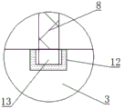
FIG. 2 is a schematic view of the structure at A in FIG. 1;
fig. 3 is a schematic top view of the present invention;
fig. 4 is a schematic front structural view of the present invention.
The reference numbers in the figures illustrate:
1 frame, 101 side frames, 102 main frames, 2 supporting legs, 3 enclosing plates, 31 bottom plates, 32 side plates, 4 dust collectors, 5 dust collecting pipes, 6 dust outlet pipes, 7 dust collecting bags, 8 net covers, 9 scraping rods, 10 motors, 11 processing doors, 12 iron sheets and 13 magnet.
Detailed Description
The technical solution in the embodiment of the present invention will be clearly and completely described below with reference to the accompanying drawings in the embodiment of the present invention; obviously, the described embodiments are only a part of the embodiments of the present invention, and not all embodiments, and all other embodiments obtained by those skilled in the art without any inventive work are within the scope of the present invention based on the embodiments of the present invention.
In the description of the present invention, it should be noted that the terms "upper", "lower", "inner", "outer", "top/bottom", and the like indicate orientations or positional relationships based on the orientations or positional relationships shown in the drawings, and are only for convenience of description and simplification of description, but do not indicate or imply that the device or element referred to must have a specific orientation, be constructed in a specific orientation, and be operated, and thus, should not be construed as limiting the present invention. Furthermore, the terms "first" and "second" are used for descriptive purposes only and are not to be construed as indicating or implying relative importance.
In the description of the present invention, it is to be noted that, unless otherwise explicitly specified or limited, the terms "mounted", "provided", "sleeved/connected", "connected", and the like are to be understood in a broad sense, such as "connected", which may be fixedly connected, detachably connected, or integrally connected; can be mechanically or electrically connected; they may be connected directly or indirectly through intervening media, or they may be interconnected between two elements. The specific meaning of the above terms in the present invention can be understood in specific cases to those skilled in the art.
Example 1:
referring to fig. 1 and 3, a textile dust collecting device of a textile machine comprises a frame 1, the frame 1 comprises a pair of side frames 101 and a main frame 102 fixedly connected between the side frames 101, the lower end of each side frame 101 is fixedly connected with a pair of supporting legs 2, a coaming 3 is connected between the two pairs of supporting legs 2, the middle part of the lower end of the coaming 3 is fixedly connected with a dust collector 4, one end of the dust collector 4 is fixedly connected with a dust collecting pipe 5, the dust collecting pipe 5 penetrates through the side wall of the coaming 3 and extends to the upper side of the coaming 3, the other end of the dust collector 4 is fixedly connected with a dust outlet pipe 6, the outer end of the dust outlet pipe 6 is in threaded connection with a dust collecting bag 7, the outer side of the dust collecting pipe 5 is provided with a mesh enclosure 8, the mesh enclosure 8 is connected with the coaming 3, the upper end of the mesh enclosure 8 is provided with a scraping rod 9, the middle part of the lower end of the main frame 102 is, can be MF9022 and Y80M 1-2.
Scrape the upper end of pole 9 and motor 10's rotation and serve all to cut the locating hole that has mutual matching, two locating hole in-connection have locking screw, be convenient for serve the dismantlement from motor 10's rotation with scraping pole 9, bounding wall 3 includes bottom plate 31 and four curb plates 32, 31 fixed connection of bottom plate is at the lower extreme of four curb plates 32, curb plate 32 fixed connection is between two adjacent landing legs 2, bottom plate 31 and curb plate 32 enclose into a cavity with landing leg 2, be used for depositing the cotton thread under 8 filtrations of screen panel, so that to the recovery processing of cotton thread.
Referring to fig. 2, a magnet 13 is fixedly connected to the lower end of the net cover 8, a groove matched with the magnet 13 is formed in the inner bottom end of the enclosing plate 3 in a chiseled mode, an iron sheet 12 is fixedly connected to the inner end of the groove, and the magnet 13 is inserted into the groove, so that the net cover 8 can be conveniently detached from the enclosing plate 3, and cotton threads on the net cover 8 can be conveniently cleaned.
Referring to fig. 4, a rectangular hole is drilled at the front end of the enclosing plate 3, a processing door 11 is hinged in the rectangular hole, cotton threads inside the enclosing plate 3 can be cleaned through the processing door 11, a sealing ring is fixedly connected to the outer end of the processing door 11, and a handle is fixedly connected to the front end of the processing door 11, so that the cotton threads are not easy to leak out from a gap between the processing door 11 and the rectangular hole.
When the dust on the weaving machine needs to be cleaned, a user can turn on a power switch of the dust collector 4 and the motor 10, the dust collector 4 sucks air through the dust collection pipe 5, the user can flap the weaving machine, the dust is raised, the dust collection pipe 5 can suck the flying dust around the weaving machine, cotton threads and the like mixed in the dust are filtered by the mesh enclosure 8, the scraping rod 9 can rotate at the upper end of the mesh enclosure 8, the cotton threads and the like adhered to the upper end of the mesh enclosure 8 are scraped, the dust entering the dust collection pipe 5 is not easily influenced, the dust entering the dust collection pipe 5 is discharged into the dust collection bag 7 from the dust outlet pipe 6 and collected, then the user can screw down the dust collection bag 7 from the dust outlet pipe 6, and the dust in the dust collection bag 7 is treated.
The above description is only the preferred embodiment of the present invention; the scope of the present invention is not limited thereto. Any person skilled in the art should also be able to cover the technical scope of the present invention by replacing or changing the technical solution and the improvement concept of the present invention with equivalents and modifications within the technical scope of the present invention.
Claims (6)
1. A textile machine weaving dirt collection device, includes frame (1), its characterized in that: the utility model discloses a dust collecting machine is characterized in that frame (1) includes a pair of side bearer (101) and body frame (102) of fixed connection between a pair of side bearer (101), the lower extreme fixedly connected with of side bearer (101) a pair of landing leg (2), two pairs be connected with bounding wall (3) between landing leg (2), the lower extreme middle part fixedly connected with dust catcher (4) of bounding wall (3), the one end fixedly connected with dust absorption pipe (5) of dust catcher (4), and dust absorption pipe (5) run through the lateral wall of bounding wall (3) and extend to the upside of bounding wall (3), the other end fixedly connected with of dust catcher (4) goes out dust pipe (6), the outer end threaded connection of play dust pipe (6) has dust bag (7), the outside of dust absorption pipe (5) is equipped with screen panel (8), and screen panel (8) are connected with bounding wall (3), the upper end of screen panel (8) is equipped with scrapes pole (, the middle part of the lower end of the main frame (102) is fixedly connected with a motor (10), and the rotating end of the motor (10) is fixedly connected with the scraping rod (9).
2. A textile machine dust collecting device as claimed in claim 1, wherein: the upper end of the scraping rod (9) and the rotating end of the motor (10) are provided with positioning holes which are matched with each other, and locking screws are connected in the two positioning holes.
3. A textile machine dust collecting device as claimed in claim 1, wherein: the lower extreme fixedly connected with magnet (13) of screen panel (8), the interior bottom end of bounding wall (3) is opened and is dug there is the recess with magnet (13) assorted, the inner fixedly connected with iron sheet (12) of recess, and magnet (13) insert and establish in the recess.
4. A textile machine dust collecting device as claimed in claim 1, wherein: the coaming (3) comprises a bottom plate (31) and four side plates (32), the bottom plate (31) is fixedly connected to the lower ends of the four side plates (32), and the side plates (32) are fixedly connected between two adjacent supporting legs (2).
5. A textile machine dust collecting device as claimed in claim 1, wherein: the front end of bounding wall (3) is cut rectangular hole, it has processing door (11) to articulate in the rectangular hole.
6. A textile machine dust collecting device as claimed in claim 5, wherein: the outer end of the treatment door (11) is fixedly connected with a sealing ring, and the front end of the treatment door (11) is fixedly connected with a handle.
Priority Applications (1)
| Application Number | Priority Date | Filing Date | Title |
|---|---|---|---|
| CN201921575749.3U CN211052131U (en) | 2019-09-22 | 2019-09-22 | Weaving machine weaving dirt collection device |
Applications Claiming Priority (1)
| Application Number | Priority Date | Filing Date | Title |
|---|---|---|---|
| CN201921575749.3U CN211052131U (en) | 2019-09-22 | 2019-09-22 | Weaving machine weaving dirt collection device |
Publications (1)
| Publication Number | Publication Date |
|---|---|
| CN211052131U true CN211052131U (en) | 2020-07-21 |
Family
ID=71593340
Family Applications (1)
| Application Number | Title | Priority Date | Filing Date |
|---|---|---|---|
| CN201921575749.3U Expired - Fee Related CN211052131U (en) | 2019-09-22 | 2019-09-22 | Weaving machine weaving dirt collection device |
Country Status (1)
| Country | Link |
|---|---|
| CN (1) | CN211052131U (en) |
Cited By (1)
| Publication number | Priority date | Publication date | Assignee | Title |
|---|---|---|---|---|
| CN113293468A (en) * | 2021-07-22 | 2021-08-24 | 江苏红金顶织造有限公司 | Weaving is collected and cleaning device with weaving quick-witted weaving dirt of weaving |
-
2019
- 2019-09-22 CN CN201921575749.3U patent/CN211052131U/en not_active Expired - Fee Related
Cited By (2)
| Publication number | Priority date | Publication date | Assignee | Title |
|---|---|---|---|---|
| CN113293468A (en) * | 2021-07-22 | 2021-08-24 | 江苏红金顶织造有限公司 | Weaving is collected and cleaning device with weaving quick-witted weaving dirt of weaving |
| CN113293468B (en) * | 2021-07-22 | 2021-09-21 | 江苏红金顶织造有限公司 | Weaving is collected and cleaning device with weaving quick-witted weaving dirt of weaving |
Similar Documents
| Publication | Publication Date | Title |
|---|---|---|
| CN218666490U (en) | Weaving is with weaving quick-witted weaving dirt collection device | |
| CN211052131U (en) | Weaving machine weaving dirt collection device | |
| CN112195549A (en) | Weaving is with weaving quick-witted weaving dirt collection device | |
| CN116603325A (en) | Cloth bag dust remover with automatic cleaning function | |
| CN209464750U (en) | A kind of air inducing dedusting filter | |
| CN214004905U (en) | Weaving is with quick-witted dust collection device of weaving | |
| CN213266844U (en) | Special dust collecting equipment of spinning machine | |
| CN108691037A (en) | Dust-extraction unit for carding machine | |
| CN113123036A (en) | Textile clothing is with destatic weaving defeathering device | |
| CN211536952U (en) | Weaving is with weaving quick-witted weaving dirt collection device | |
| CN216677395U (en) | Convenient sack cleaner of dismantling | |
| CN215137852U (en) | Weaving machine weaving dirt collection device | |
| CN211497932U (en) | Broken yarn collecting device for spinning | |
| CN220426275U (en) | Weaving is with weaving dirt collection cleaning device | |
| CN208680035U (en) | A kind of refuse yarn cleaner of Weaving device | |
| CN208757221U (en) | A kind of dust collect plant for textile process | |
| CN214551894U (en) | Built-in cyclone bag-type dust collector | |
| CN218925495U (en) | Cleaning device for sesame oil processing | |
| CN213467184U (en) | Weaving machine weaving dirt collection device | |
| CN213652765U (en) | Dust collector is used in spinning production | |
| CN213944270U (en) | Dust collecting device for textile mill | |
| CN213942484U (en) | A dust storage device for weaving factory removes dust | |
| CN216404771U (en) | Non-woven fabrics side cut waste recycling device | |
| CN213885345U (en) | Weaving dust shaker that can reciprocal clearance filter screen adhesion impurity | |
| CN220977251U (en) | Cotton processing waste velvet recovery device |
Legal Events
| Date | Code | Title | Description |
|---|---|---|---|
| GR01 | Patent grant | ||
| GR01 | Patent grant | ||
| CF01 | Termination of patent right due to non-payment of annual fee |
Granted publication date: 20200721 Termination date: 20200922 |
|
| CF01 | Termination of patent right due to non-payment of annual fee |