CN211049435U - Body fluid retention device for medical examination - Google Patents
Body fluid retention device for medical examination Download PDFInfo
- Publication number
- CN211049435U CN211049435U CN201921903989.1U CN201921903989U CN211049435U CN 211049435 U CN211049435 U CN 211049435U CN 201921903989 U CN201921903989 U CN 201921903989U CN 211049435 U CN211049435 U CN 211049435U
- Authority
- CN
- China
- Prior art keywords
- body fluid
- pad
- connector
- medical examination
- fixedly connected
- Prior art date
- Legal status (The legal status is an assumption and is not a legal conclusion. Google has not performed a legal analysis and makes no representation as to the accuracy of the status listed.)
- Expired - Fee Related
Links
Images


Landscapes
- Sampling And Sample Adjustment (AREA)
Abstract
The utility model discloses a ware is kept somewhere with body fluid for medical examination, including base and sampling tube, the upper end rear fixed mounting of base has the bracing piece, the upper end fixedly connected with position sleeve of bracing piece, the front end fixedly connected with position circle of position sleeve, flexible groove has been seted up to the inner wall of position circle, the inside swing joint in flexible groove has the roof, the rear end surface of roof is located the first spring of the fixed position of the inside in flexible groove, the fixed position that is located the below of position circle in the middle of the upper end of base has the rubber pad, sampling tube fixed mounting is in the inside of position circle, the upper end fixed mounting of sampling tube has the connector, the inside fixed mounting of connector has the rubber circle, the upper end fixed mounting of connector has the funnel. The utility model discloses can improve the stability of keeping somewhere the ware, avoid keeping somewhere the ware and taking place to empty in the use, make things convenient for the collection of body fluid moreover, have the practicality.
Description
Technical Field
The utility model relates to the technical field of medical appliances, in particular to a body fluid retention device for medical examination.
Background
The body fluid of patient often needs to be detected among the medical examination process to detect patient's state of an illness according to patient's body fluid composition analysis, the patient need take a sample through the body fluid retention ware when carrying out the urine sample.
However, the existing body fluid indwelling device for medical examination has certain defects in use, is poor in stability and easy to topple over in use, so that collected urine is leaked, and the body fluid indwelling device needs to pour the urine in a urine cup into a test tube in use, so that the urine is easy to spill out in the process, so that the two hands of a user are polluted, certain influence is brought to the use process, and therefore the body fluid indwelling device is improved at present.
SUMMERY OF THE UTILITY MODEL
The utility model aims at solving the defects existing in the prior art and providing a body fluid retention device for medical examination.
In order to achieve the above purpose, the utility model adopts the following technical scheme:
ware is kept somewhere to body fluid for medical examination, including base and sampling tube, the upper end rear fixed mounting of base has the bracing piece, the upper end fixedly connected with position sleeve of bracing piece, the front end fixedly connected with position circle of position sleeve, flexible groove has been seted up to the inner wall of position circle, the inside swing joint in flexible groove has the roof, the rear end surface of roof is located the first spring of the fixed position of the inside in flexible groove, the fixed position that is located the below of position circle in the middle of the upper end of base has the rubber pad, sampling tube fixed mounting is in the inside of position circle, the upper end fixed mounting of sampling tube has the connector, the inside fixed mounting of connector has the rubber circle, the upper end fixed mounting of connector has the funnel.
Preferably, the rear end of first spring and the inner wall fixed connection in flexible groove, the roof passes through first spring and position circle swing joint, the quantity of roof is three groups, three groups the roof is the annular distribution at the inner wall of position circle.
Preferably, the outer surface of the upper end of the rubber pad is provided with a groove, the groove is of an arc-shaped structure, and the central point of the positioning ring and the central point of the groove are positioned on the same vertical line.
Preferably, the connector is a nut structure, the upper end one side fixedly connected with handle of funnel, the lower extreme of funnel runs through the inside that the connector is located the sampling tube.
Preferably, the outer fixed surface of the lower end of the base is provided with a foot pad, the outer fixed surface of the lower end of the foot pad is provided with a non-slip mat, the non-slip mat is made of rubber, and the outer fixed surface of the upper end of the foot pad is connected with a screw rod.
Preferably, the outer fixed surface of the lower end of the base is provided with a shock pad, the lower end of the shock pad is movably connected with a base plate, the inner upper end of the shock pad is fixedly provided with a damping pad, and the upper end of the base plate is located inside the shock pad and fixedly connected with a second spring.
Compared with the prior art, the beneficial effects of the utility model are that:
1. in the utility model, the base and the positioning ring can improve the stability of the indwelling device through the arranged base, the supporting rod, the positioning sleeve, the positioning ring, the telescopic groove, the top plate, the first spring and the rubber pad, and the urine spill caused by the toppling of the indwelling device in the using process is avoided, thereby improving the using effect of the body fluid indwelling device;
2. in the utility model, the funnel is inserted on the sampling tube to facilitate urine sampling, the connector at the upper end of the sampling tube can ensure that the funnel is fixed at the upper end of the sampling tube, the body fluid retention device does not need to dump urine into a test tube after the urine is obtained, and the urine directly flows into the sampling tube through flowing, thereby facilitating the use of the retention device;
to sum up, the utility model discloses can improve the stability of keeping somewhere the ware, avoid keeping somewhere the ware and taking place to empty in the use, make things convenient for the collection of body fluid moreover, have the practicality.
Drawings
FIG. 1 is a schematic view of the overall structure of a first embodiment of a body fluid retention device for medical examination according to the present invention;
FIG. 2 is a schematic view of a foot pad of the embodiment of the body fluid indwelling device for medical examination according to the present invention;
FIG. 3 is a schematic structural view of a positioning ring of the body fluid indwelling device for medical examination according to the present invention;
FIG. 4 is a schematic view showing the overall structure of a second embodiment of the body fluid indwelling device for medical examination according to the present invention;
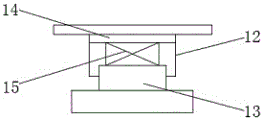
fig. 5 is a schematic structural view of a shock pad in a second embodiment of the body fluid indwelling device for medical examination according to the present invention.
In the figure: the device comprises a base 1, a supporting rod 2, a positioning sleeve 3, a positioning ring 4, a telescopic groove 5, a top plate 6, a first spring 7, a rubber pad 8, a foot pad 9, a non-slip pad 10, a screw rod 11, a shock pad 12, a backing plate 13, a damping pad 14, a second spring 15, a sampling tube 16, a connector 17, a rubber ring 18 and a funnel 19.
Detailed Description
The technical solutions in the embodiments of the present invention will be described clearly and completely with reference to the accompanying drawings in the embodiments of the present invention, and it is obvious that the described embodiments are only some embodiments of the present invention, not all embodiments.
The first embodiment is as follows:
referring to fig. 1-3, the body fluid indwelling device for medical examination comprises a base 1 and a sampling tube 16, a support rod 2 is fixedly mounted at the rear of the upper end of the base 1, a positioning sleeve 3 is fixedly connected to the upper end of the support rod 2, a positioning ring 4 is fixedly connected to the front end of the positioning sleeve 3, a telescopic groove 5 is formed in the inner wall of the positioning ring 4, a top plate 6 is movably connected to the inner part of the telescopic groove 5, a first spring 7 is fixedly connected to the position of the outer surface of the rear end of the top plate 6 in the telescopic groove 5, a rubber pad 8 is fixedly mounted below the positioning ring 4 in the middle of the upper end of the base 1, the sampling tube 16 is fixedly mounted in the positioning ring 4, a connector 17 is fixedly mounted at the upper end of the sampling tube 16, a rubber ring 18 is fixedly.
Wherein, the rear end of first spring 7 and the inner wall fixed connection of flexible groove 5, roof 6 are through first spring 7 and 4 swing joint of position circle, and the quantity of roof 6 is three groups, and three groups of roof 6 are the annular distribution at the inner wall of position circle 4.
Wherein, the upper end surface of rubber pad 8 is seted up flutedly, and the recess is the arc structure, and the central point of position circle 4 and the central point of recess are located same vertical line.
Wherein, the connector 17 is a screw cap structure, one side of the upper end of the funnel 19 is fixedly connected with a handle, and the lower end of the funnel 19 penetrates through the connector 17 and is positioned in the sampling tube 16.
Wherein, the fixed surface of the lower extreme of base 1 installs callus on the sole 9, and the fixed surface of the lower extreme of callus on the sole 9 installs the slipmat 10, and the material of slipmat 10 is rubber, and the outer fixed surface in the upper end of callus on the sole 9 is connected with screw rod 11.
Example two:
referring to fig. 3-5, the body fluid indwelling device for medical examination comprises a base 1 and a sampling tube 16, a support rod 2 is fixedly mounted at the rear of the upper end of the base 1, a positioning sleeve 3 is fixedly connected to the upper end of the support rod 2, a positioning ring 4 is fixedly connected to the front end of the positioning sleeve 3, a telescopic groove 5 is formed in the inner wall of the positioning ring 4, a top plate 6 is movably connected to the inner portion of the telescopic groove 5, a first spring 7 is fixedly connected to the position of the outer surface of the rear end of the top plate 6 in the telescopic groove 5, a rubber pad 8 is fixedly mounted below the positioning ring 4 in the middle of the upper end of the base 1, the sampling tube 16 is fixedly mounted in the positioning ring 4, a connector 17 is fixedly mounted at the upper end of the sampling tube 16, a rubber ring 18 is fixedly.
Wherein, the rear end of first spring 7 and the inner wall fixed connection of flexible groove 5, roof 6 are through first spring 7 and 4 swing joint of position circle, and the quantity of roof 6 is three groups, and three groups of roof 6 are the annular distribution at the inner wall of position circle 4.
Wherein, the upper end surface of rubber pad 8 is seted up flutedly, and the recess is the arc structure, and the central point of position circle 4 and the central point of recess are located same vertical line.
Wherein, the connector 17 is a screw cap structure, one side of the upper end of the funnel 19 is fixedly connected with a handle, and the lower end of the funnel 19 penetrates through the connector 17 and is positioned in the sampling tube 16.
Wherein, the outer fixed surface of the lower extreme of base 1 installs shock pad 12, and the lower extreme swing joint of shock pad 12 has backing plate 13, and the inside upper end fixed mounting of shock pad 12 has damping pad 14, and the position fixed connection that the upper end of backing plate 13 is located the inside of shock pad 12 has second spring 15.
The working principle is as follows: when a male uses the disposable urine collection device, the user holds the supporting rod 2 at the upper end of the base 1 by one hand to take up the sampling tube 16 and then urinates in the funnel 19, when the female uses the disposable urine collection device, the disposable urine collection device is placed and stably used through the foot pad 9 or the shock absorption pad 12 at the lower end of the base 1, the anti-slip pad 10 on the foot pad 9 can increase friction, the second spring 15 on the shock absorption pad 12 can play a role in shock absorption, so that the disposable urine collection device is more stable when in use, the urine in the funnel 19 directly flows into the sampling tube 16 without being poured into a test tube, and the use of the disposable urine collection device is facilitated; the utility model discloses can improve the stability of keeping somewhere the ware, avoid keeping somewhere the ware and taking place to empty in the use, make things convenient for the collection of body fluid moreover, have the practicality.
The above, only be the concrete implementation of the preferred embodiment of the present invention, but the protection scope of the present invention is not limited thereto, and any person skilled in the art is in the technical scope of the present invention, according to the technical solution of the present invention and the utility model, the concept of which is equivalent to replace or change, should be covered within the protection scope of the present invention.
Claims (6)
1. The body fluid indwelling device for medical examination comprises a base (1) and a sampling tube (16), and is characterized in that a supporting rod (2) is fixedly mounted at the rear of the upper end of the base (1), a positioning sleeve (3) is fixedly connected to the upper end of the supporting rod (2), a positioning ring (4) is fixedly connected to the front end of the positioning sleeve (3), a telescopic groove (5) is formed in the inner wall of the positioning ring (4), a top plate (6) is movably connected to the inner part of the telescopic groove (5), a first spring (7) is fixedly connected to the position, located inside the telescopic groove (5), of the outer surface of the rear end of the top plate (6), a rubber pad (8) is fixedly mounted in the middle of the upper end of the base (1) and located below the positioning ring (4), the sampling tube (16) is fixedly mounted inside the positioning ring (4), and a connector (17) is fixedly mounted at the upper end of, the inside fixed mounting of connector (17) has rubber circle (18), the upper end fixed mounting of connector (17) has funnel (19).
2. The body fluid indwelling device for medical examination according to claim 1, wherein the rear end of the first spring (7) is fixedly connected with the inner wall of the telescopic groove (5), the top plates (6) are movably connected with the positioning ring (4) through the first spring (7), the number of the top plates (6) is three, and the three groups of the top plates (6) are annularly distributed on the inner wall of the positioning ring (4).
3. The body fluid indwelling device for medical examination according to claim 1, wherein the rubber pad (8) is provided with a groove on the outer surface of the upper end thereof, the groove is of an arc-shaped structure, and the center point of the positioning ring (4) and the center point of the groove are located on the same vertical line.
4. The body fluid indwelling device for medical examination according to claim 1, wherein the connector (17) is in a nut structure, a handle is fixedly connected to one side of the upper end of the funnel (19), and the lower end of the funnel (19) penetrates through the connector (17) and is located inside the sampling tube (16).
5. The body fluid indwelling device for medical examination according to claim 1, wherein a foot pad (9) is fixedly mounted on the outer surface of the lower end of the base (1), a non-slip pad (10) is fixedly mounted on the outer surface of the lower end of the foot pad (9), the non-slip pad (10) is made of rubber, and a screw (11) is fixedly connected to the outer surface of the upper end of the foot pad (9).
6. The body fluid indwelling device for medical examination according to claim 1, wherein a shock pad (12) is fixedly mounted on the outer surface of the lower end of the base (1), a cushion plate (13) is movably connected to the lower end of the shock pad (12), a damping pad (14) is fixedly mounted on the upper end of the inside of the shock pad (12), and a second spring (15) is fixedly connected to the position of the upper end of the cushion plate (13) inside the shock pad (12).
Priority Applications (1)
| Application Number | Priority Date | Filing Date | Title |
|---|---|---|---|
| CN201921903989.1U CN211049435U (en) | 2019-11-06 | 2019-11-06 | Body fluid retention device for medical examination |
Applications Claiming Priority (1)
| Application Number | Priority Date | Filing Date | Title |
|---|---|---|---|
| CN201921903989.1U CN211049435U (en) | 2019-11-06 | 2019-11-06 | Body fluid retention device for medical examination |
Publications (1)
| Publication Number | Publication Date |
|---|---|
| CN211049435U true CN211049435U (en) | 2020-07-21 |
Family
ID=71583410
Family Applications (1)
| Application Number | Title | Priority Date | Filing Date |
|---|---|---|---|
| CN201921903989.1U Expired - Fee Related CN211049435U (en) | 2019-11-06 | 2019-11-06 | Body fluid retention device for medical examination |
Country Status (1)
| Country | Link |
|---|---|
| CN (1) | CN211049435U (en) |
-
2019
- 2019-11-06 CN CN201921903989.1U patent/CN211049435U/en not_active Expired - Fee Related
Similar Documents
| Publication | Publication Date | Title |
|---|---|---|
| CN201046204Y (en) | Simple workrest for medicine changing of lower limbs | |
| CN205483682U (en) | Medical testing urine cup | |
| CN211049435U (en) | Body fluid retention device for medical examination | |
| CN204816586U (en) | Multi -functional clinical laboratory uses test tube | |
| CN209148373U (en) | A kind of urine specimen leaves and takes device | |
| CN208784748U (en) | A kind of blood collection auxiliary frame | |
| CN203965198U (en) | Urine sample sample collecting apparatus | |
| CN213589327U (en) | Multi-functional auxiliary frame for enema | |
| CN218900021U (en) | Medical bed hair basin convenient to accomodate | |
| CN209966437U (en) | Urine cup for clinical laboratory | |
| CN212973216U (en) | Novel urine receiving device for gynecological and obstetrical nursing | |
| CN204758340U (en) | Urine collector | |
| CN216050241U (en) | Auxiliary frame of body weight scale | |
| CN200948272Y (en) | Convenient infusion stand | |
| CN212632755U (en) | Medicine is test tube fixing device for laboratory | |
| CN219273116U (en) | Multifunctional chemical experiment connecting device | |
| CN210347207U (en) | Clinical laboratory's urine collector | |
| CN211633373U (en) | Medical urine collection device | |
| CN204346748U (en) | The just rare or watery stool of a kind of diarrhoea patient adopts closet | |
| CN214967068U (en) | A catheterization device for experimental animals | |
| CN210752809U (en) | Blood sampling test tube fixed bolster | |
| CN209975660U (en) | Urinal with urine collecting function | |
| CN111024454A (en) | Urine sample collection device | |
| CN214486951U (en) | Endocrine sample test tube | |
| CN213274440U (en) | Medicine inspection is with stabilizing anti-overflow graduated flask |
Legal Events
| Date | Code | Title | Description |
|---|---|---|---|
| GR01 | Patent grant | ||
| GR01 | Patent grant | ||
| CF01 | Termination of patent right due to non-payment of annual fee |
Granted publication date: 20200721 Termination date: 20211106 |
|
| CF01 | Termination of patent right due to non-payment of annual fee |