CN211046157U - Constant temperature low-voltage control cabinet - Google Patents
Constant temperature low-voltage control cabinet Download PDFInfo
- Publication number
- CN211046157U CN211046157U CN201920869227.8U CN201920869227U CN211046157U CN 211046157 U CN211046157 U CN 211046157U CN 201920869227 U CN201920869227 U CN 201920869227U CN 211046157 U CN211046157 U CN 211046157U
- Authority
- CN
- China
- Prior art keywords
- fixedly connected
- fan
- cabinet
- protection cover
- control cabinet
- Prior art date
- Legal status (The legal status is an assumption and is not a legal conclusion. Google has not performed a legal analysis and makes no representation as to the accuracy of the status listed.)
- Expired - Fee Related
Links
Images


Abstract
The utility model provides a constant temperature low-voltage control cabinet, the intelligent cabinet temperature adjusting device comprises a cabinet body, a protection cover plate of internal portion lateral wall fixedly connected with of cabinet, a fan of the inboard fixedly connected with of protection cover plate, the dust screen has been arranged to fan one side, the heater strip has been arranged to dust screen one side, No. two protection cover plates of internal portion opposite side fixedly connected with of cabinet, No. two fans of the inboard fixedly connected with of protection cover plate, the internal portion top fixedly connected with condenser box of cabinet, condenser box one side turn-on connection has the condenser pipe, and the condenser pipe is located No. two fan one sides. The novel design, simple structure has good heating and cooling function to can make the inside temperature of switch board keep at certain within range, with the normal work of assurance electrical part, and have certain dehumidification effect, prevent that the condensation from appearing when carrying out the cold and heat exchange in the inside temperature of switch board, avoid causing the damage to the electrical part, further hoisting device's practicality.
Description
Technical Field
The utility model relates to a switch board technical field specifically is a constant temperature low-voltage control cabinet.
Background
The control cabinet is formed by assembling switch equipment, measuring instruments, protective electrical appliances and auxiliary equipment in a closed or semi-closed metal cabinet or on a screen according to the electrical wiring requirements, and the arrangement of the control cabinet meets the requirements of normal operation of an electric power system, is convenient to overhaul and does not endanger the safety of people and surrounding equipment. In normal operation, the circuit can be switched on or off by means of a manual or automatic switch. When the fault or abnormal operation occurs, the circuit is cut off or an alarm is given by the aid of the protective electric appliance. The measuring instrument can display various parameters in operation, and can also adjust some electrical parameters to prompt or send out signals for deviation from normal working state.
The existing control cabinet does not have good cooling and heating effects when working, so that the electric device inside the device is easily influenced by temperature and cannot normally operate, the temperature inside the cabinet body cannot be kept in a constant range, the service life of the electric device inside the device is seriously influenced, the control cabinet does not have a good dehumidification effect, the requirements of people cannot be met, and therefore, the constant-temperature low-voltage control cabinet is provided.
SUMMERY OF THE UTILITY MODEL
The utility model provides a technical problem that solve provides a constant temperature low-voltage control cabinet, the modern design, simple structure has good heating and cooling function, thereby can make the inside temperature of switch board keep in certain within range, with the normal work of assurance electrical part, and have certain dehumidification effect, prevent that the condensation from appearing in the inside temperature of switch board when carrying out the cold and heat exchange, avoid causing the damage to the electrical part, further hoisting device's practicality, with the problem of proposing in solving above-mentioned background art.
The utility model provides a technical problem adopt following technical scheme to realize:
the utility model provides a constant temperature low-voltage control cabinet, includes the cabinet body, a lateral wall fixedly connected with protection cover plate of internal portion of cabinet, fan No. one of the inboard fixedly connected with of protection cover plate, the dust screen has been arranged to fan one side, the heater strip has been arranged to dust screen one side, No. two protection cover plates of the internal opposite side fixedly connected with of cabinet, No. two fan of the inboard fixedly connected with of protection cover plate, the internal portion top fixedly connected with cooling cylinder of cabinet, condenser cylinder one side turn-on connection has the condenser pipe, and the condenser pipe is located No. two fan one sides, condenser cylinder bottom end fixedly connected with temperature sensor, humidity transducer has been arranged to temperature sensor one side, the miniature dehumidifier of internal bottom end fixedly connected with of cabinet.
Further, a partition plate is arranged at the top end of the miniature dehumidifier, moisture absorption holes are arranged inside the partition plate, and a mounting plate is fixedly connected between the first protective cover plate and the second protective cover plate.
Further, the inside fixedly connected with micro-water pump of condenser box, the condenser box top turn-on connection has notes liquid mouth, the inside equipartition of first guard shield board and No. two guard shield boards has been provided with the air vent.
Further, the baffle is fixedly connected with the inner side wall of the cabinet body, the miniature water pump is in conduction connection with one end of the condenser pipe, the dust screen is made of a metal material, and the condenser box is made of a heat insulating material.
Further, fan, heater strip, No. two fans and miniature pump all pass through external controller and temperature sensor electric connection, miniature dehumidifier passes through external controller and humidity transducer electric connection.
Compared with the prior art, the beneficial effects of the utility model are that:
1. can detect the inside temperature of switch board through temperature sensor, when the inside temperature of switch board is higher than the regulation numerical value, temperature sensor then can give external controller with information transfer, make it give No. two fans and miniature pump and carry out the circular telegram work, it is inside to make the miniature pump carry the condensing agent of condensing box inside the condensing tube, thereby can make the condensing tube absorb the heat on every side, in order to reduce the temperature around the condensing tube, and can blow the low-temperature gas around the condensing tube to the internal portion of cabinet through the air vent through No. two fans, thereby can cool down the temperature of the internal portion of cabinet, prevent that the electrical part from receiving the influence of high temperature at the during operation.
2. When the inside temperature of switch board is less than certain numerical value, temperature sensor then can give information for external controller once more, makes it give fan and heater strip and carry out the circular telegram work, and wherein the heater strip can heat the air around, and a fan then can blow the gas after the heating to cabinet internal portion through the air vent to can heat the inside temperature of switch board, make the inside temperature that can keep invariable of switch board, in order to guarantee the normal work of electrical part.
3. Can detect the humidity of the internal portion of cabinet through humidity transducer, when the humidity of the internal portion of cabinet reachs certain numerical value, then can transmit information for miniature dehumidifier through external controller, make it carry out work, thereby can take out the moisture of the internal portion of cabinet through the moisture absorption pore pair, in order to guarantee the drying of the internal portion of cabinet, prevent that the switch board from producing the condensation when cold and hot exchange, avoid causing the damage to the inside electrical part of switch board, the practicality of device has further been promoted.
Drawings
Fig. 1 is a schematic view of the overall structure of the present invention.
Fig. 2 is a schematic view of the internal structure of a first protective cover plate of the present invention.
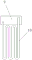
Fig. 3 is a schematic view of the structure of the condensation tube of the present invention.
Fig. 4 is a schematic view of the vent structure of the present invention.
Detailed Description
In order to make the technical means, creation features, achievement purposes and functions of the present invention easy to understand, the present invention is further described below with reference to the specific drawings.
As shown in fig. 1 to 4, in operation, an electrical device can be conveniently installed in the control cabinet by an operator through the mounting plate 16, so that the device can be conveniently operated, after the electrical device is operated, the temperature sensor 11 is powered on to detect the temperature in the control cabinet, when the temperature in the control cabinet is higher than a specified value, the temperature sensor 11 transmits information to the external controller, so that the external controller can be powered on to the second fan 7 and the micro water pump 9, the micro water pump 9 can convey the condensing agent in the condensing box 8 to the inside of the condensing pipe 10, so that the condensing pipe 10 can absorb the ambient heat to reduce the ambient temperature of the condensing pipe 10, and the low-temperature gas around the condensing pipe 10 can be blown to the inside of the cabinet body 1 through the vent hole 18 through the second fan 7, so that the temperature in the cabinet body 1 can be reduced, the temperature sensor 11 can transmit information to the external controller again when the temperature in the control cabinet is lower than a certain value, so that the external controller can supply power to the fan 3 and the heating wire 5 for work, wherein the heating wire 5 can heat the surrounding air, the fan 3 can blow the heated air into the cabinet body 1 through the vent hole 18, so as to heat the temperature in the control cabinet, so that the temperature in the control cabinet can be kept constant, the normal work of the electric device is ensured, the practicability of the control cabinet is greatly improved, the humidity in the cabinet body 1 can be detected through the humidity sensor 12, when the humidity in the cabinet body 1 reaches a certain value, the information can be transmitted to the micro dehumidifier 13 through the external controller to work, thereby the moisture in the cabinet body 1 can be pumped out through the moisture absorption holes 15 to ensure the dryness of the interior of the cabinet body 1, prevent the condensation of the control cabinet during the cold and heat exchange, avoid the damage to the electric devices in the control cabinet, further improve the practicability of the device, the electrical components may be shielded from the micro dehumidifier 13 by the baffle 14, to facilitate good operation of the micro dehumidifier 13, the dust screen 4 has good dust-proof effect, prevents dust from falling on the surface of the heating wire 5, avoids influencing the normal work of the heating wire 5, and the first protective cover plate 2 and the second protective cover plate 6 respectively protect the heating wire 5 and the condenser pipe 10 well, thereby avoiding the heating wire 5 and the condenser pipe 10 from being damaged, the liquid injection port 17 is convenient for workers to inject the condensing agent into the condensing box 8 so as to ensure the sufficiency of the condensing agent.
The basic principles and the main features of the invention and the advantages of the invention have been shown and described above. It will be understood by those skilled in the art that the present invention is not limited to the above embodiments, and that the foregoing embodiments and descriptions are provided only to illustrate the principles of the present invention without departing from the spirit and scope of the present invention. The scope of the invention is defined by the appended claims and equivalents thereof.
Claims (5)
1. The utility model provides a constant temperature low-voltage control cabinet, includes the cabinet body (1), its characterized in that: the improved cabinet is characterized in that a first protection cover plate (2) is fixedly connected to one side wall inside the cabinet body (1), a first fan (3) is fixedly connected to the inner side of the first protection cover plate (2), a dust screen (4) is arranged on one side of the first fan (3), a heating wire (5) is arranged on one side of the dust screen (4), a second protection cover plate (6) is fixedly connected to the other side inside the cabinet body (1), a second fan (7) is fixedly connected to the inner side of the second protection cover plate (6), a condensing box (8) is fixedly connected to the top end inside the cabinet body (1), a condensing pipe (10) is connected to one side of the condensing box (8), the condensing pipe (10) is located on one side of the second fan (7), a temperature sensor (11) is fixedly connected to the bottom end of the condensing box (8), and a humidity sensor (12), the inner bottom end of the cabinet body (1) is fixedly connected with a miniature dehumidifier (13).
2. A thermostatic low pressure control cabinet according to claim 1, characterized in that: baffle (14) have been arranged on miniature dehumidifier (13) top, baffle (14) inside arrangement has moisture absorption hole (15), fixedly connected with mounting panel (16) between guard shield board (2) and No. two guard shield boards (6).
3. A thermostatic low pressure control cabinet according to claim 2, characterized in that: the inside fixedly connected with micro-water pump (9) of condensation case (8), the top turn-on connection of condensation case (8) has notes liquid mouth (17), air vent (18) have been put to the inside equipartition of guard plate board (2) and No. two guard plate boards (6).
4. A thermostatic low pressure control cabinet according to claim 3, characterized in that: baffle (14) and cabinet body (1) inside wall fixed connection, miniature pump (9) and condenser pipe (10) one end turn-on connection, dust screen (4) are the dust screen of metal material preparation, condenser box (8) are the condenser box of thermal insulation material preparation.
5. A thermostatic low pressure control cabinet according to claim 3, characterized in that: the first fan (3), the heating wire (5), the second fan (7) and the micro water pump (9) are all electrically connected with the temperature sensor (11) through an external controller, and the micro dehumidifier (13) is electrically connected with the humidity sensor (12) through the external controller.
Priority Applications (1)
| Application Number | Priority Date | Filing Date | Title |
|---|---|---|---|
| CN201920869227.8U CN211046157U (en) | 2019-06-11 | 2019-06-11 | Constant temperature low-voltage control cabinet |
Applications Claiming Priority (1)
| Application Number | Priority Date | Filing Date | Title |
|---|---|---|---|
| CN201920869227.8U CN211046157U (en) | 2019-06-11 | 2019-06-11 | Constant temperature low-voltage control cabinet |
Publications (1)
| Publication Number | Publication Date |
|---|---|
| CN211046157U true CN211046157U (en) | 2020-07-17 |
Family
ID=71559840
Family Applications (1)
| Application Number | Title | Priority Date | Filing Date |
|---|---|---|---|
| CN201920869227.8U Expired - Fee Related CN211046157U (en) | 2019-06-11 | 2019-06-11 | Constant temperature low-voltage control cabinet |
Country Status (1)
| Country | Link |
|---|---|
| CN (1) | CN211046157U (en) |
Cited By (1)
| Publication number | Priority date | Publication date | Assignee | Title |
|---|---|---|---|---|
| CN112867318A (en) * | 2021-01-19 | 2021-05-28 | 宝武杰富意特殊钢有限公司 | Protection device, caliper protection alarm system and method |
-
2019
- 2019-06-11 CN CN201920869227.8U patent/CN211046157U/en not_active Expired - Fee Related
Cited By (1)
| Publication number | Priority date | Publication date | Assignee | Title |
|---|---|---|---|---|
| CN112867318A (en) * | 2021-01-19 | 2021-05-28 | 宝武杰富意特殊钢有限公司 | Protection device, caliper protection alarm system and method |
Similar Documents
| Publication | Publication Date | Title |
|---|---|---|
| CN207474948U (en) | A kind of moisture-proof high temperature-proof power screen cabinet | |
| CN207234169U (en) | A kind of switchgear with antifogging function | |
| CN202975882U (en) | Online intelligent condensation-proof dehumidification system | |
| CN211046157U (en) | Constant temperature low-voltage control cabinet | |
| CN203071450U (en) | Electronic-type miniature dehumidifier | |
| CN203367803U (en) | Distribution box | |
| CN211320635U (en) | Intelligent separated low-voltage complete switch equipment | |
| CN206559745U (en) | A kind of network cabinet of condensation-preventing device | |
| CN205882972U (en) | Engine generator with operational environment governing system | |
| CN216872585U (en) | Anticreep warning block terminal | |
| CN203259900U (en) | Draining-type humidity controller | |
| CN212392481U (en) | Special condensation dehydrating unit of switch board | |
| CN213185122U (en) | Intelligent electronic control device | |
| CN213717273U (en) | Dampproofing switch board | |
| CN203645976U (en) | Industrial air cooler | |
| CN211630540U (en) | Dehumidification mechanism for instrument control cabinet | |
| CN211859214U (en) | Constant temperature control cabinet | |
| CN220342677U (en) | Integrated control cabinet | |
| CN213638721U (en) | Sealed waterproof electrical appliance control box | |
| CN219067611U (en) | Enhanced heat dissipation type electric control cabinet | |
| CN213755295U (en) | Control cabinet for boats and ships | |
| CN220441127U (en) | Electric control device convenient for heat dissipation | |
| CN205485692U (en) | PLC switch board | |
| CN215071042U (en) | Constant temperature tension control electric cabinet | |
| CN219513527U (en) | American box transformer device |
Legal Events
| Date | Code | Title | Description |
|---|---|---|---|
| GR01 | Patent grant | ||
| GR01 | Patent grant | ||
| CF01 | Termination of patent right due to non-payment of annual fee |
Granted publication date: 20200717 |
|
| CF01 | Termination of patent right due to non-payment of annual fee |