CN211025925U - Lime agitating unit for building - Google Patents
Lime agitating unit for building Download PDFInfo
- Publication number
- CN211025925U CN211025925U CN201920952360.XU CN201920952360U CN211025925U CN 211025925 U CN211025925 U CN 211025925U CN 201920952360 U CN201920952360 U CN 201920952360U CN 211025925 U CN211025925 U CN 211025925U
- Authority
- CN
- China
- Prior art keywords
- fixedly connected
- lime
- stirring
- agitator tank
- motor
- Prior art date
- Legal status (The legal status is an assumption and is not a legal conclusion. Google has not performed a legal analysis and makes no representation as to the accuracy of the status listed.)
- Active
Links
Images


Abstract
The utility model discloses a lime agitating unit for building, including base, water tank, motor case and agitator tank, water tank fixed connection is in base top one side, base top middle part fixedly connected with support frame, agitator tank fixed connection is on the support frame top, be equipped with rabbling mechanism in the agitator tank, motor case fixed connection is on the agitator tank top, be equipped with power unit in the motor case, motor fixed connection is in one side of motor bottom end inner wall, first through-hole has all been seted up on motor bottom end inner wall and agitator tank top, one side of motor top end inner wall is rotated and is connected with first bull stick. Compared with the prior art, the utility model discloses lime agitating unit for building passes through the rabbling mechanism rotation that power unit drove in the agitator tank, dials the board and concentrates the lime of agitator tank both sides toward the middle part, and the spiral stirring leaf stirs lime for lime stirring is more even in the agitator tank, and the structure is ingenious, and the practicality is strong.
Description
Technical Field
The utility model relates to a construction technical field especially relates to a lime agitating unit for building.
Background
A stirrer is a constructional engineering machine and mainly used for stirring building materials such as cement, sand and stone, various dry-mixed mortar and the like, the stirrer is very various, but in actual use, most of the stirrers cannot fully stir lime cement, materials are wasted, and the progress of engineering is influenced
Through search, the patent with the Chinese patent application number of CN205797114U discloses a lime stirring device for decoration, which comprises a bottom plate, a stirring box, a motor, a spring, a roller, a screw rod, a steel wire rope, a stirring rod and the like. The device in the above patent suffers from the following disadvantages: the motor drives the lead screw to reciprocate to pull the steel wire rope so as to drive the stirring rod to rotate, lime in the stirring box is stirred, the method has good idea but poor practicability, the lime at four corners in the stirring box cannot be stirred, and the stirring is insufficient through swinging stirring.
SUMMERY OF THE UTILITY MODEL
The utility model aims at solving the defects existing in the prior art and providing a lime stirring device for building.
In order to achieve the above purpose, the utility model adopts the following technical scheme:
the utility model provides a lime agitating unit for building, includes base, water tank, motor case and agitator tank, water tank fixed connection is in base top one side, base top middle part fixedly connected with support frame, agitator tank fixed connection is on the support frame top, be equipped with rabbling mechanism in the agitator tank, motor case fixed connection is on the agitator tank top, be equipped with power unit in the motor tank.
Further, power unit includes the motor, motor fixed connection is in one side of motor case bottom end inner wall, first through-hole has all been seted up on motor case bottom end inner wall and agitator tank top, one side of motor case top end inner wall is rotated and is connected with first bull stick, and just first bull stick extends to inside the agitator tank in first through-hole department.
Furthermore, a first bevel gear is fixedly connected to an output shaft of the motor, a second bevel gear is fixedly connected to the outer side of the top end of the first rotating rod, and the first bevel gear is meshed with the second bevel gear.
Further, rabbling mechanism includes first gear and spiral stirring leaf, the both sides difference fixedly connected with backup pad of agitator tank top inner wall, two the fixed frame of backup pad bottom fixedly connected with, the second through-hole has been seted up at fixed frame top middle part, first pivot runs through the second through-hole of fixed frame, first gear fixed connection is in the first pivot top outside, spiral stirring leaf fixed connection is in the first pivot bottom outside.
Further, fixed frame bottom both sides are rotated respectively and are connected with the second bull stick, two the equal fixedly connected with second gear in second bull stick top outside, two second gear and first gear looks adaptation, two a plurality of boards of dialling of the outside equidistance fixedly connected with of second bull stick.
Further, agitator tank bottom one side card is equipped with the discharge gate, the agitator tank has the gate in discharge gate one side sliding connection, base top one side is equipped with connects the silo, silo under agitator tank opposite side top fixedly connected with, fixedly connected with water pipe between water tank top one side and agitator tank one side, the inside booster pump that is equipped with of water tank.
Furthermore, the first rotating rod is fixedly connected with a third bevel gear outside the top end inside the stirring box, a third through hole is formed in one side of the supporting plate, and the supporting plate is rotatably connected with a third rotating rod in the third through hole.
Furthermore, a fourth bevel gear is fixedly connected to one end of the third rotating rod and meshed with the third bevel gear, fan blades are fixedly connected to the other end of the third rotating rod, and a plurality of heat dissipation holes are formed in one side of the top end of the stirring box.
The utility model has the advantages that:
1. through setting up rabbling mechanism, power unit drives first bull stick and rotates, and then drives the spiral stirring leaf and rotate, drives the second bull stick through gear drive and rotates, dials the synchronous rotation of board, concentrates the lime of agitator tank both sides toward the middle part, and the spiral stirring leaf stirs lime for lime stirring is more even in the agitator tank.
2. Through setting up power unit, motor work drives first bevel gear and rotates, drives first bull stick through second bevel gear and rotates, and then drives the lime of rabbling mechanism in to the agitator tank and stir, and the structure is ingenious, and the practicality is strong.
3. Through setting up flabellum and louvre, because a large amount of heats can be shed in lime stirring process, drive the flabellum through the bevel gear structure and rotate, outside the heat follow louvre discharge agitator tank with the agitator tank in, rational in infrastructure, greatly increased the life of device.
Compared with the prior art, the utility model discloses lime agitating unit for building passes through the rabbling mechanism rotation that power unit drove in the agitator tank, dials the board and concentrates the lime of agitator tank both sides toward the middle part, and the spiral stirring leaf stirs lime for lime stirring is more even in the agitator tank, and the structure is ingenious, and the practicality is strong.
Drawings
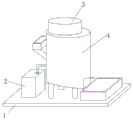
FIG. 1 is a front view of a lime stirring apparatus for construction as set forth in example 1;
FIG. 2 is a front view of a lime stirring apparatus for construction as set forth in example 1;
FIG. 3 is a front view of a lime stirring apparatus for construction as set forth in example 2.
In the figure: 1-base, 2-water tank, 3-motor box, 4-stirring box, 5-motor, 6-first bevel gear, 7-first rotating rod, 8-second bevel gear, 9-fixed frame, 10-second gear, 11-first gear, 12-second rotating rod, 13-shifting plate, 14-spiral stirring blade, 15-third bevel gear, 16-fourth bevel gear, 17-third rotating rod and 18-fan blade.
Detailed Description
The technical solution of the present patent will be described in further detail with reference to the following embodiments.
Reference will now be made in detail to embodiments of the present patent, examples of which are illustrated in the accompanying drawings, wherein like or similar reference numerals refer to the same or similar elements or elements having the same or similar function throughout. The embodiments described below with reference to the drawings are exemplary only for the purpose of explaining the present patent and are not to be construed as limiting the present patent.
In the description of this patent, it is to be understood that the terms "center," "upper," "lower," "front," "rear," "left," "right," "vertical," "horizontal," "top," "bottom," "inner," "outer," and the like are used in the orientations and positional relationships indicated in the drawings for the convenience of describing the patent and for the simplicity of description, and are not intended to indicate or imply that the referenced devices or elements must have a particular orientation, be constructed and operated in a particular orientation, and are not to be considered limiting of the patent.
In the description of this patent, it is noted that unless otherwise specifically stated or limited, the terms "mounted," "connected," and "disposed" are to be construed broadly and can include, for example, fixedly connected, disposed, detachably connected, disposed, or integrally connected and disposed. The specific meaning of the above terms in this patent may be understood by those of ordinary skill in the art as appropriate.
Example 1
Referring to fig. 1-2, a lime agitating unit for building includes base 1, water tank 2, motor case 3 and agitator tank 4, 2 bolted connections of water tank are in 1 top one side of base, the welding of 1 top middle part of base has the support frame, 4 bolted connections of agitator tank are on the support frame top, be equipped with rabbling mechanism in the agitator tank 4, 3 bolted connections of motor case are on 4 tops of agitator tank, be equipped with power unit in the motor case 3.
Wherein, power unit includes motor 5, 5 bolted connection of motor is in one side of 3 bottom inner walls of motor case, first through-hole has all been seted up on 3 bottom inner walls of motor case and 4 tops of agitator tank, one side of 3 top inner walls of motor case is rotated through the pivot and is connected with first bull stick 7, and just first bull stick 7 extends to agitator tank 4 inside at first through-hole department, motor 5 output shaft welding has first bevel gear 6, the welding of 7 top outsides of first bull stick has second bevel gear 8, first bevel gear 6 and the meshing of second bevel gear 8 drive the lime of rabbling mechanism in to agitator tank 4 through motor 5 and stir, and ingenious structure, the practicality is strong.
Wherein, the stirring mechanism comprises a first gear 11 and a spiral stirring blade 14, two supporting plates are respectively welded on two sides of the inner wall of the top end of the stirring box 4, a fixed frame 9 is welded at the bottom end of the two supporting plates, a second through hole is arranged in the middle of the top end of the fixed frame 9, the first rotating rod 7 penetrates through the second through hole of the fixed frame 9, the first gear 11 is welded on the outer side of the top end of the first rotating rod 7, the spiral stirring blade 14 is welded on the outer side of the bottom end of the first rotating rod 7, two sides of the bottom end of the fixed frame 9 are respectively connected with a second rotating rod 12 in a rotating way through a rotating shaft, a second gear 10 is welded on the outer side of the top end of the two second rotating rods 12, the two second gears 10 are matched with the first gear 11, a plurality of stirring plates 13 are welded on the outer part of the two second rotating rods 12 in, base 1 top one side is equipped with connects the silo, 4 opposite side top welding of agitator tank have down the silo, bolted connection has the water pipe between 2 top one sides of water tank and 4 one sides of agitator tank, 2 inside ISG50-160 type water pumps that are equipped with of water tank, dial board 13 and concentrate the lime of 4 both sides of agitator tank toward the middle part, spiral stirring leaf 14 stirs lime for lime stirring is more even in the agitator tank 4.
The working principle is as follows: the staff pours lime into agitator tank 4 from the feed chute, the start power supply, the water pump is in taking out the water in water tank 2 into agitator tank 4, motor 5 works, it rotates to drive first bevel gear 6, it rotates to drive first bull stick 7 through second bevel gear 8, first gear 11 rotates, it rotates to drive the second bull stick through the second gear, spiral stirring leaf 14 and group board 13 synchronous rotation, it concentrates the lime of agitator tank both sides toward the middle part to dial board 13, spiral stirring leaf 14 stirs lime, the messenger is with lime stirring in agitator tank 4, open the gate after having stirred, lime falls into from the discharge gate and connects the silo in.
Example 2
Referring to fig. 3, this embodiment compares in embodiment 1, for the heat dissipation problem in solving agitator tank 4, first bull stick 7 has third bevel gear 15 in the inside top outside welding of agitator tank 4, the third through-hole has been seted up to backup pad one side, the backup pad is rotated through the pivot in third through-hole department and is connected with third bull stick 17, third bull stick 17 one end welding has fourth bevel gear 16, fourth bevel gear 16 and the meshing of third bevel gear 15, third bull stick 17 other end welding has flabellum 18, a plurality of louvres have been seted up to agitator tank 4 top one side.
The working principle is as follows: the staff pours lime into agitator tank 4 from the feed chute, the power supply is started, the water pump is in with the water pumping in water tank 2 in agitator tank 4, motor 5 works, drive first bevel gear 6 and rotate, it rotates to drive first bull stick 7 through second bevel gear 8, first gear 11 rotates, it rotates to drive the second bull stick through the second gear, spiral stirring leaf 14 and group board 13 synchronous rotation, it concentrates the lime of agitator tank both sides toward the middle part to dial board 13, spiral stirring leaf 14 stirs lime, make with lime stirring in agitator tank 4, first bull stick 7 drives third bevel gear 15 and rotates, and then drive fourth bevel gear 16, it rotates to drive flabellum 18 through third bull stick 17, discharge the heat in agitator tank 4 from the louvre, open the gate after the stirring, lime falls into from the discharge gate and connects the silo.
The above, only be the concrete implementation of the preferred embodiment of the present invention, but the protection scope of the present invention is not limited thereto, and any person skilled in the art is in the technical scope of the present invention, according to the technical solution of the present invention and the utility model, the concept of which is equivalent to replace or change, should be covered within the protection scope of the present invention.
Claims (8)
1. The utility model provides a lime agitating unit for building, includes base (1), water tank (2), motor case (3) and agitator tank (4), its characterized in that, water tank (2) fixed connection is in base (1) top one side, base (1) top middle part fixedly connected with support frame, agitator tank (4) fixed connection is on the support frame top, be equipped with rabbling mechanism in agitator tank (4), motor case (3) fixed connection is on agitator tank (4) top, be equipped with power unit in motor case (3).
2. The lime stirring device for building as claimed in claim 1, wherein the power mechanism comprises a motor (5), the motor (5) is fixedly connected to one side of the inner wall of the bottom end of the motor box (3), first through holes are formed in the inner wall of the bottom end of the motor box (3) and the top end of the stirring box (4), a first rotating rod (7) is rotatably connected to one side of the inner wall of the top end of the motor box (3), and the first rotating rod (7) extends to the inside of the stirring box (4) at the first through hole.
3. The lime stirring device for building as claimed in claim 2, wherein a first bevel gear (6) is fixedly connected to the output shaft of the motor (5), a second bevel gear (8) is fixedly connected to the outer side of the top end of the first rotating rod (7), and the first bevel gear (6) is engaged with the second bevel gear (8).
4. The lime stirring device for building of claim 2, wherein the stirring mechanism comprises a first gear (11) and a spiral stirring blade (14), the two sides of the inner wall of the top end of the stirring box (4) are respectively and fixedly connected with a supporting plate, two supporting plates are fixedly connected with a fixing frame (9) at the bottom end, a second through hole is formed in the middle of the top end of the fixing frame (9), the first rotating rod (7) penetrates through the second through hole of the fixing frame (9), the first gear (11) is fixedly connected to the outer side of the top end of the first rotating rod (7), and the spiral stirring blade (14) is fixedly connected to the outer side of the bottom end of the first rotating rod (7).
5. The lime stirring device for building as claimed in claim 4, wherein two sides of the bottom end of the fixed frame (9) are respectively and rotatably connected with second rotating rods (12), the outer sides of the top ends of the two second rotating rods (12) are respectively and fixedly connected with second gears (10), the two second gears (10) are matched with the first gear (11), and a plurality of shifting plates (13) are fixedly connected to the outer parts of the two second rotating rods (12) at equal intervals.
6. The lime stirring device for building as claimed in claim 5, wherein a discharge port is blocked at one side of the bottom end of the stirring tank (4), the stirring tank (4) is slidably connected with a gate at one side of the discharge port, a receiving trough is arranged at one side of the top end of the base (1), a discharging trough is fixedly connected at the other side of the top end of the stirring tank (4), a water pipe is fixedly connected between one side of the top end of the water tank (2) and one side of the stirring tank (4), and a booster pump is arranged inside the water tank (2).
7. The lime stirring device for building as claimed in claim 6, wherein the first rotating rod (7) is fixedly connected with a third bevel gear (15) at the outer side of the top end of the stirring box (4), a third through hole is formed at one side of the supporting plate, and a third rotating rod (17) is rotatably connected with the third through hole of the supporting plate.
8. The lime stirring device for buildings according to claim 7, wherein one end of the third rotating rod (17) is fixedly connected with a fourth bevel gear (16), the fourth bevel gear (16) is meshed with the third bevel gear (15), the other end of the third rotating rod (17) is fixedly connected with a fan blade (18), and one side of the top end of the stirring box (4) is provided with a plurality of heat dissipation holes.
Priority Applications (1)
| Application Number | Priority Date | Filing Date | Title |
|---|---|---|---|
| CN201920952360.XU CN211025925U (en) | 2019-06-24 | 2019-06-24 | Lime agitating unit for building |
Applications Claiming Priority (1)
| Application Number | Priority Date | Filing Date | Title |
|---|---|---|---|
| CN201920952360.XU CN211025925U (en) | 2019-06-24 | 2019-06-24 | Lime agitating unit for building |
Publications (1)
| Publication Number | Publication Date |
|---|---|
| CN211025925U true CN211025925U (en) | 2020-07-17 |
Family
ID=71544710
Family Applications (1)
| Application Number | Title | Priority Date | Filing Date |
|---|---|---|---|
| CN201920952360.XU Active CN211025925U (en) | 2019-06-24 | 2019-06-24 | Lime agitating unit for building |
Country Status (1)
| Country | Link |
|---|---|
| CN (1) | CN211025925U (en) |
Cited By (2)
| Publication number | Priority date | Publication date | Assignee | Title |
|---|---|---|---|---|
| CN112473982A (en) * | 2020-11-09 | 2021-03-12 | 萍乡市昌盛水泥厂有限公司 | Superfine grinding system for cement production |
| CN115845645A (en) * | 2022-11-16 | 2023-03-28 | 无锡容大环境科技有限公司 | Preparation device and preparation method of slaked lime emulsion for wastewater treatment |
-
2019
- 2019-06-24 CN CN201920952360.XU patent/CN211025925U/en active Active
Cited By (3)
| Publication number | Priority date | Publication date | Assignee | Title |
|---|---|---|---|---|
| CN112473982A (en) * | 2020-11-09 | 2021-03-12 | 萍乡市昌盛水泥厂有限公司 | Superfine grinding system for cement production |
| CN115845645A (en) * | 2022-11-16 | 2023-03-28 | 无锡容大环境科技有限公司 | Preparation device and preparation method of slaked lime emulsion for wastewater treatment |
| CN115845645B (en) * | 2022-11-16 | 2023-08-15 | 无锡容大环境科技有限公司 | Preparation device and preparation method of slaked lime emulsion for wastewater treatment |
Similar Documents
| Publication | Publication Date | Title |
|---|---|---|
| CN211025925U (en) | Lime agitating unit for building | |
| CN218609028U (en) | Material mixing device for building engineering | |
| CN209903594U (en) | Cement paste stirring structure | |
| CN207359349U (en) | A kind of construction concrete mixer easy to cleaning | |
| CN216230079U (en) | Cement self-leveling mortar stirring and conveying device | |
| CN214810212U (en) | Uniform chloropropanone stirring kettle | |
| CN214871638U (en) | Novel concrete mixing equipment is used in construction in room | |
| CN211590705U (en) | Material conveying device for building construction | |
| CN210906179U (en) | Enamel reaction kettle for producing water reducing agent | |
| CN212068588U (en) | Engineering construction configuration device | |
| CN220428814U (en) | Stirring device and concrete mixing material | |
| CN215549754U (en) | High-efficient mixing arrangement of cement mortar for building | |
| CN210729303U (en) | Liquid mixing high-speed mixer | |
| CN217834161U (en) | High-efficient agitating unit of concrete | |
| CN217621361U (en) | Stirring equipment for building mortar | |
| CN216321312U (en) | Agitating unit for civil engineering | |
| CN215549781U (en) | Mortar agitating unit for afforestation construction | |
| CN213946980U (en) | High-efficient mixer | |
| CN210357087U (en) | Solid water glass melting device | |
| CN211541816U (en) | Energy-saving anti-crack plastering mortar preparation device | |
| CN207206758U (en) | A kind of portable trucd mixer | |
| CN220719798U (en) | C35P6 concrete preparation agitated vessel | |
| CN213829642U (en) | Building concrete mixing device | |
| CN217490497U (en) | Material stirring device for factory building construction | |
| CN217967622U (en) | Cement paste stirring device |
Legal Events
| Date | Code | Title | Description |
|---|---|---|---|
| GR01 | Patent grant | ||
| GR01 | Patent grant |