CN211019548U - Protective housing for internet equipment - Google Patents
Protective housing for internet equipment Download PDFInfo
- Publication number
- CN211019548U CN211019548U CN201921609565.4U CN201921609565U CN211019548U CN 211019548 U CN211019548 U CN 211019548U CN 201921609565 U CN201921609565 U CN 201921609565U CN 211019548 U CN211019548 U CN 211019548U
- Authority
- CN
- China
- Prior art keywords
- casing
- sides
- shell
- welded
- protective case
- Prior art date
- Legal status (The legal status is an assumption and is not a legal conclusion. Google has not performed a legal analysis and makes no representation as to the accuracy of the status listed.)
- Active
Links
Images


Landscapes
- Casings For Electric Apparatus (AREA)
Abstract
The utility model relates to the technical field of internet equipment, in particular to a protective shell for internet equipment, which comprises a shell, wherein elastic plates are welded on two sides of the shell, one side of the elastic plate, which is away from the shell, is fixedly connected with a protection plate, springs are clamped at the top and the bottom of two sides of the shell, one end of the spring, which is away from the shell, is clamped with the surface of the protection plate, and vertical plates are welded on two sides of the top of the shell; the utility model discloses an elastic plate cushions the impact force, improves protecting sheathing's protecting effect to further improve the security of casing internal plant body, further cushion impact force through the spring, thereby further improve protecting sheathing's protecting effect, improve protecting sheathing's security through the roof, avoid the invasion of rainwater and the threat of falling object in the high altitude, thereby further improve protecting sheathing's protecting effect, solved the not good problem of protecting sheathing protecting effect in the past.
Description
Technical Field
The utility model relates to an internet equipment technical field specifically is a protecting sheathing for internet equipment.
Background
The protective housing is used for protecting internal articles, plays an important role in production and life of people, and along with the development of science and technology, various protective housings come into force, and the protective housing for internet equipment belongs to one of them.
However, most of the conventional protective housings for internet devices are poor in protection effect and easy to damage due to impact force, so that internal articles are damaged, property loss is brought to users, and the requirements of the current market cannot be met.
SUMMERY OF THE UTILITY MODEL
An object of the utility model is to provide a protective housing for internet equipment possesses the good advantage of protecting effect, has solved the not good problem of current protective housing protecting effect.
In order to achieve the above object, the utility model provides a following technical scheme: the utility model provides an internet is protecting sheathing for equipment, includes the casing, the elastic plate has all been welded to the both sides of casing, one side fixedly connected with guard plate of casing is kept away from to the elastic plate, the top and the equal joint in bottom of casing both sides have the spring, the one end that the casing was kept away from to the spring is connected with the surface looks joint of guard plate, the riser has all been welded to the both sides at casing top, the top welding of riser has the roof, the bottom bolt of casing has heat dissipation mechanism, heat dissipation mechanism is used for reducing the inside temperature of casing.
Preferably, the heat dissipation mechanism comprises a vertical pipe, the top of the vertical pipe is communicated with the bottom of the shell, a support rod is bolted to the inner wall of the vertical pipe, and a fan is bolted to one end, far away from the inner wall of the vertical pipe, of the support rod through a bolt.
Preferably, the wire holes are formed in the two sides of the bottom of the shell, and the ventilation holes are formed in the two sides of the shell.
Preferably, the bracing piece has all been welded to the both sides of casing inner chamber bottom, the top welding of bracing piece has places the board, the top of placing the board is provided with equipment body, the threaded rod has all been welded to the both sides at equipment body top, the surface cover of threaded rod is equipped with the apron, the bottom of apron and the top contact of equipment body, the surface threaded connection of threaded rod has the thread bush.
Preferably, the top of the front surface of the shell is movably connected with an access door through a hinge, and the front surface of the access door is provided with a lock cylinder in a penetrating mode.
Preferably, the fixing plates are welded on two sides of the bottom of the front surface and the back surface of the shell, and fixing holes are formed in the tops of the fixing plates.
Compared with the prior art, the beneficial effects of the utility model are as follows:
the utility model discloses an elastic plate cushions the impact force, improves protecting sheathing's protecting effect to further improve the security of casing internal plant body, further cushion impact force through the spring, thereby further improve protecting sheathing's protecting effect, improve protecting sheathing's security through the roof, avoid the invasion of rainwater and the threat of falling object in the high altitude, thereby further improve protecting sheathing's protecting effect, solved the not good problem of protecting sheathing protecting effect in the past.
Drawings
FIG. 1 is a schematic structural view of the present invention;
FIG. 2 is a front view of the structure of the present invention;
FIG. 3 is a schematic cross-sectional view of the heat dissipation mechanism of the present invention;
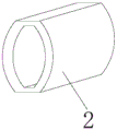
fig. 4 is a three-dimensional schematic view of the elastic plate of the present invention.
In the figure: 1. a housing; 2. an elastic plate; 3. a protection plate; 4. a spring; 5. a vertical plate; 6. a top plate; 7. a heat dissipation mechanism; 8. a vertical tube; 9. a strut; 10. a fan; 11. a wire hole; 12. a vent hole; 13. a support bar; 14. placing the plate; 15. an apparatus body; 16. a threaded rod; 17. a cover plate; 18. a threaded sleeve; 19. an access door; 20. a lock cylinder; 21. a fixing plate; 22. and (7) fixing holes.
Detailed Description
The technical solutions in the embodiments of the present invention will be described clearly and completely with reference to the accompanying drawings in the embodiments of the present invention, and it is obvious that the described embodiments are only some embodiments of the present invention, not all embodiments. Based on the embodiments in the present invention, all other embodiments obtained by a person skilled in the art without creative work belong to the protection scope of the present invention.
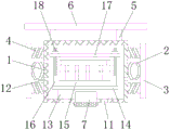
Referring to fig. 1-4, a protective housing for internet equipment comprises a housing 1, wherein elastic plates 2 are welded on two sides of the housing 1, a protection plate 3 is fixedly connected on one side of the elastic plates 2 away from the housing 1, springs 4 are clamped on the top and the bottom of the two sides of the housing 1, one end of each spring 4 away from the housing 1 is clamped with the surface of the protection plate 3, vertical plates 5 are welded on two sides of the top of the housing 1, a top plate 6 is welded on the tops of the vertical plates 5, a heat dissipation mechanism 7 is bolted on the bottom of the housing 1, the heat dissipation mechanism 7 is used for reducing the temperature inside the housing 1, the impact force is buffered through the elastic plates 2, the protection effect of the protective housing is improved, so that the safety of an equipment body 15 inside the housing 1 is further improved, the impact force is further buffered through the springs 4, the protection effect of the protective housing is further improved, and the safety of the protective housing is, avoid the invasion of rainwater and the threat of falling object to further improve protective housing's protecting effect, solved the not good problem of protective housing protecting effect in the past.
In this embodiment, heat dissipation mechanism 7 includes standpipe 8, and the top of standpipe 8 and the bottom intercommunication of casing 1, the inner wall bolt of standpipe 8 have connect branch 9, and the one end that 8 inner walls of standpipe were kept away from to branch 9 has connected fan 10 through the bolt, through setting up fan 10 for drive circulation of air improves the heat transfer effect, thereby improves internet equipment and uses protecting sheathing's radiating effect.
In this embodiment, line hole 11 has all been seted up to the both sides of casing 1 bottom, and ventilation hole 12 has all been seted up to the both sides of casing 1, through setting up line hole 11 for the business turn over of wire, through setting up ventilation hole 12, is used for the circulation of air.
In this embodiment, bracing piece 13 has all been welded to the both sides of 1 inner chamber bottom of casing, the welding of the top of bracing piece 13 has places board 14, the top of placing board 14 is provided with equipment body 15, threaded rod 16 has all been welded to the both sides at equipment body 15 top, the surface cover of threaded rod 16 is equipped with apron 17, the bottom of apron 17 and the top contact of equipment body 15, threaded rod 16's surperficial threaded connection has thread bush 18, place board 14 through setting up, be used for supporting equipment body 15, through setting up threaded rod 16, apron 17 and thread bush 18, be used for fixing equipment body 15, improve equipment body 15's stability.
In this embodiment, there is access door 19 at the top of the front of casing 1 through hinge swing joint, and access door 19's front is run through and is provided with lock core 20, and through setting up access door 19 and lock core 20, the person of facilitating the use overhauls the inside equipment body 15 of casing 1.
In this embodiment, the fixing plates 21 are welded on the two sides of the front and the back of the casing 1, the fixing holes 22 are formed in the top of the fixing plates 21, and the fixing plates 21 and the fixing holes 22 are arranged for installing and fixing the internet equipment protection shell.
During the use, drive guard plate 3 through the impact force and remove, remove extrusion elastic plate 2 and spring 4 through guard plate 3, produce elastic potential energy through elastic plate 2 and spring 4 deformation, cushion impact force through elastic potential energy, improve protecting sheathing's protecting effect, thereby further improve 1 internal plant of casing body 15's security, improve protecting sheathing's security through roof 6, avoid the invasion of rainwater and the threat of falling object, thereby further improve protecting sheathing's protecting effect.
Although embodiments of the present invention have been shown and described, it will be appreciated by those skilled in the art that changes, modifications, substitutions and alterations can be made in these embodiments without departing from the principles and spirit of the invention, the scope of which is defined in the appended claims and their equivalents.
Claims (6)
1. The utility model provides a protective housing for internet equipment, includes casing (1), its characterized in that: elastic plate (2) are all welded to the both sides of casing (1), one side fixedly connected with guard plate (3) of casing (1) are kept away from in elastic plate (2), the top and the equal joint in bottom of casing (1) both sides have spring (4), the one end of casing (1) and the surperficial looks joint of guard plate (3) are kept away from in spring (4), riser (5) have all been welded to the both sides at casing (1) top, the top welding of riser (5) has roof (6), the bottom bolt joint of casing (1) has heat dissipation mechanism (7), heat dissipation mechanism (7) are used for reducing the inside temperature of casing (1).
2. The protective case for internet devices as claimed in claim 1, wherein: heat dissipation mechanism (7) include standpipe (8), the top of standpipe (8) and the bottom intercommunication of casing (1), the inner wall bolt joint of standpipe (8) has branch (9), the one end that standpipe (8) inner wall was kept away from in branch (9) has fan (10) through the bolt joint.
3. The protective case for internet devices as claimed in claim 1, wherein: line hole (11) have all been seted up to the both sides of casing (1) bottom, ventilation hole (12) have all been seted up to the both sides of casing (1).
4. The protective case for internet devices as claimed in claim 1, wherein: the utility model discloses a novel multifunctional electric soldering iron, including casing (1), bracing piece (13) all weld in the both sides of casing (1) inner chamber bottom, the top welding of bracing piece (13) has places board (14), the top of placing board (14) is provided with equipment body (15), threaded rod (16) all weld in the both sides at equipment body (15) top, the surface cover of threaded rod (16) is equipped with apron (17), the bottom of apron (17) contacts with the top of equipment body (15), the surperficial threaded connection of threaded rod (16) has thread bush (18).
5. The protective case for internet devices as claimed in claim 1, wherein: the top on the front of the shell (1) is movably connected with an access door (19) through a hinge, and the front of the access door (19) is provided with a lock cylinder (20) in a penetrating mode.
6. The protective case for internet devices as claimed in claim 1, wherein: fixed plates (21) are welded on two sides of the front and back bottoms of the shell (1), and fixed holes (22) are formed in the tops of the fixed plates (21).
Priority Applications (1)
| Application Number | Priority Date | Filing Date | Title |
|---|---|---|---|
| CN201921609565.4U CN211019548U (en) | 2019-09-25 | 2019-09-25 | Protective housing for internet equipment |
Applications Claiming Priority (1)
| Application Number | Priority Date | Filing Date | Title |
|---|---|---|---|
| CN201921609565.4U CN211019548U (en) | 2019-09-25 | 2019-09-25 | Protective housing for internet equipment |
Publications (1)
| Publication Number | Publication Date |
|---|---|
| CN211019548U true CN211019548U (en) | 2020-07-14 |
Family
ID=71507096
Family Applications (1)
| Application Number | Title | Priority Date | Filing Date |
|---|---|---|---|
| CN201921609565.4U Active CN211019548U (en) | 2019-09-25 | 2019-09-25 | Protective housing for internet equipment |
Country Status (1)
| Country | Link |
|---|---|
| CN (1) | CN211019548U (en) |
Cited By (2)
| Publication number | Priority date | Publication date | Assignee | Title |
|---|---|---|---|---|
| CN112413047A (en) * | 2020-11-04 | 2021-02-26 | 南京光略科技有限公司 | Anti-collision damping system of communication terminal |
| CN116222736A (en) * | 2023-02-17 | 2023-06-06 | 东营市艾瑞斯环保科技有限公司 | Audio frequency detection method and system |
-
2019
- 2019-09-25 CN CN201921609565.4U patent/CN211019548U/en active Active
Cited By (3)
| Publication number | Priority date | Publication date | Assignee | Title |
|---|---|---|---|---|
| CN112413047A (en) * | 2020-11-04 | 2021-02-26 | 南京光略科技有限公司 | Anti-collision damping system of communication terminal |
| CN116222736A (en) * | 2023-02-17 | 2023-06-06 | 东营市艾瑞斯环保科技有限公司 | Audio frequency detection method and system |
| CN116222736B (en) * | 2023-02-17 | 2023-10-27 | 东营市艾瑞斯环保科技有限公司 | Audio frequency detection method and system |
Similar Documents
| Publication | Publication Date | Title |
|---|---|---|
| CN211019548U (en) | Protective housing for internet equipment | |
| CN211480117U (en) | Graphene battery protection device with buffering effect | |
| CN215580111U (en) | Cable antidetonation support for engineering | |
| CN113523633A (en) | Welding device for battery module | |
| CN210461521U (en) | Relay rack mounting frame | |
| CN210074526U (en) | Stabilize effectual block terminal | |
| CN215770762U (en) | Transformer that shock resistance is strong | |
| CN206850254U (en) | A kind of electrical control cubicles internal partition structure | |
| CN210225985U (en) | Regulator cubicle dustcoat structure | |
| CN211982284U (en) | Building electrical cabinet | |
| CN210694218U (en) | Portable network switch | |
| CN107135622A (en) | A kind of electric component box of solar energy | |
| CN207883432U (en) | A kind of transformer with insulation function | |
| CN215008989U (en) | Combined outdoor low-voltage power distribution cabinet | |
| CN220189417U (en) | Noise reduction isolation cover of converter transformer | |
| CN206865104U (en) | Intelligent vertical type cross connection grounding case | |
| CN216450756U (en) | Storage battery for new forms of energy that heat dispersion is good | |
| CN217444537U (en) | Effectual high safe type new forms of energy battery box of protection | |
| CN215956423U (en) | Protective housing based on carbon fiber plate | |
| CN212224873U (en) | Steel construction building enclosure device | |
| CN205212938U (en) | IP camera | |
| CN213485058U (en) | Terminal equipment capable of realizing language self-adaption | |
| CN218441698U (en) | Fire detection alarm with excellent anti-seismic performance for intelligent fire fighting | |
| CN213545919U (en) | Power consumption efficiency monitoring terminal | |
| CN212967464U (en) | Excitation type dual power transfer switch with high-efficient heat dissipation |
Legal Events
| Date | Code | Title | Description |
|---|---|---|---|
| GR01 | Patent grant | ||
| GR01 | Patent grant | ||
| TR01 | Transfer of patent right | ||
| TR01 | Transfer of patent right |
Effective date of registration: 20210611 Address after: 136000 group 7, Beimen Committee, Lishu Town, Lishu County, Siping City, Jilin Province Patentee after: Henan Address before: No.29, group 7, yuanjiaqiao village, Jinxing, Nanlong Town, Nanbu County, Nanchong City, Sichuan Province Patentee before: Chen Wenrong |