CN211018295U - Portable intelligent multifunctional charging panel - Google Patents
Portable intelligent multifunctional charging panel Download PDFInfo
- Publication number
- CN211018295U CN211018295U CN201920961397.9U CN201920961397U CN211018295U CN 211018295 U CN211018295 U CN 211018295U CN 201920961397 U CN201920961397 U CN 201920961397U CN 211018295 U CN211018295 U CN 211018295U
- Authority
- CN
- China
- Prior art keywords
- charging
- mobile phone
- box cover
- box body
- module
- Prior art date
- Legal status (The legal status is an assumption and is not a legal conclusion. Google has not performed a legal analysis and makes no representation as to the accuracy of the status listed.)
- Expired - Fee Related
Links
Images


Landscapes
- Telephone Function (AREA)
- Charge And Discharge Circuits For Batteries Or The Like (AREA)
Abstract
本实用新型提供了便携式智能多功能充电面板,所述盒体上设置有两个插脚,所述盒体上还卡接有盒盖,所述盒盖的外侧壁上固定设置有一个重力感应手机支架,所述盒盖的内侧壁上固定设置有一个微动开关,所述微动开关的动作簧片延伸出所述盒盖并固定在所述重力感应手机支架的下支撑脚上;所述盒体内设置有WIFI物联网模块、降压器、以及无线充电模块。本实用新型可以直接插在插座上,不占用桌面空间;同时设置有物联网模块和定时器,可以远程控制充电时间,防止手机过充电发热,有利于延长手机电池使用寿命,预防安全事故;另外还设置有USB充电接口作为第二充电口,供不带无线充电功能的手机充电。
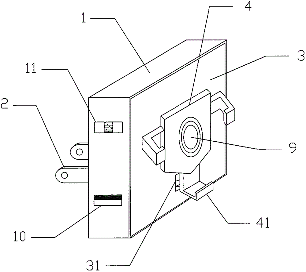
The utility model provides a portable intelligent multi-function charging panel. The box body is provided with two pins, a box cover is also clamped on the box body, and a gravity-sensing mobile phone is fixed on the outer side wall of the box cover. A bracket, a micro switch is fixed on the inner side wall of the box cover, and the action reed of the micro switch extends out of the box cover and is fixed on the lower support foot of the gravity-sensing mobile phone bracket; the The box body is provided with a WIFI Internet of Things module, a voltage reducer, and a wireless charging module. The utility model can be directly inserted into the socket and does not occupy the desktop space; at the same time, an Internet of Things module and a timer are provided, which can remotely control the charging time, prevent the mobile phone from overcharging and heat up, and help prolong the service life of the mobile phone battery and prevent safety accidents; in addition A USB charging interface is also provided as a second charging port for charging a mobile phone without a wireless charging function.
Description
技术领域technical field
本实用新型涉及无线充电装置技术领域,具体为便携式智能多功能充电面板。The utility model relates to the technical field of wireless charging devices, in particular to a portable intelligent multifunctional charging panel.
背景技术Background technique
随着科技的发展,对手机进行无线充电越来越适合人们的需求;但现有的无线充电装置需要放在如桌面等水平平面上,占用空间,而且功能单一,没有定时功能,手机一直进行充电,具有一定的安全风险,现有的大部分是有线充电,没有无线充电功能,或者不具备无线有线能够同时充电的功能。With the development of science and technology, wireless charging of mobile phones is more and more suitable for people's needs; but the existing wireless charging devices need to be placed on a horizontal plane such as a desktop, occupying space, and have a single function and no timing function. Charging has certain safety risks. Most of the existing ones are wired charging without wireless charging function, or do not have the function of wireless and wired charging at the same time.
实用新型内容Utility model content
针对上述存在的技术不足,本实用新型的目的是提供便携式智能多功能充电面板,可以直接插接在墙体插座上,不占用桌面空间;同时设置有物联网模块和定时器,可以远程控制充电时间,防止手机过充电发热,有利于延长手机电池使用寿命,预防安全事故;另外还设置有磁吸有线充电接口作为第二充电口,供不带无线充电功能的手机充电。In view of the above-mentioned technical deficiencies, the purpose of this utility model is to provide a portable intelligent multi-function charging panel, which can be directly plugged into a wall socket without occupying desktop space; at the same time, an Internet of Things module and a timer are provided, which can remotely control charging Time, prevent the mobile phone from overcharging and heating, which is beneficial to prolong the service life of the mobile phone battery and prevent safety accidents; in addition, a magnetic suction wired charging interface is provided as a second charging port for charging mobile phones without wireless charging function.
为解决上述技术问题,本实用新型采用如下技术方案:In order to solve the above-mentioned technical problems, the utility model adopts the following technical solutions:
本实用新型提供便携式智能多功能充电面板,包括盒体,其特征在于,所述盒体上设置有两个插脚,所述盒体上还卡接有盒盖,所述盒盖的外侧壁上固定设置有一个重力感应手机支架,所述盒盖的内侧壁上固定设置有一个微动开关,所述微动开关的动作簧片延伸出所述盒盖并固定在所述重力感应手机支架的下支撑脚上;所述盒体内设置有WIFI物联网模块、降压器、以及无线充电模块,所述重力感应手机支架上嵌设有无线充电线圈,所述降压器、无线充电模块以及所述无线充电线圈电性连接,所述插脚与所述物联网模块、降压器电性连接;所述WIFI物联网模块内置有定时器,所述WIFI物联网模块与所述微动开关电性连接;所述盒体的其中一个侧壁上开设有两个矩形孔,其中一个矩形孔内嵌设有一个USB充电接口,另一个矩形孔内嵌设有手动双刀双掷开关,所述手动双刀双掷开关串联在所述插脚与所述降压器之间。The utility model provides a portable intelligent multi-function charging panel, comprising a box body, characterized in that the box body is provided with two pins, the box body is also clamped with a box cover, and the outer side wall of the box cover is on the outer side wall. A gravity-sensing mobile phone bracket is fixedly arranged, a micro-switch is fixedly arranged on the inner side wall of the box cover, and the action reed of the micro-switch extends out of the box cover and is fixed on the gravity-sensing mobile phone bracket. on the lower support feet; the box body is provided with a WIFI Internet of Things module, a voltage reducer, and a wireless charging module, and a wireless charging coil is embedded on the gravity-sensing mobile phone bracket, and the voltage reducer, the wireless charging module and all The wireless charging coil is electrically connected, and the pins are electrically connected to the IoT module and the voltage reducer; the WIFI IoT module has a built-in timer, and the WIFI IoT module is electrically connected to the micro switch. One of the side walls of the box body is provided with two rectangular holes, one of which is embedded with a USB charging interface, and the other rectangular hole is embedded with a manual double-pole double-throw switch. A double-pole double-throw switch is connected in series between the pin and the voltage reducer.
优选地,所述盒盖上还开设有供所述动作簧片滑动的滑槽。Preferably, the box cover is also provided with a chute for the action reed to slide.
优选地,所述降压器为220V交流转5V直流降压模块。Preferably, the step-down device is a 220V AC to 5V DC step-down module.
优选地,所述USB充电接口与所述降压器电性连接。Preferably, the USB charging interface is electrically connected to the voltage reducer.
本实用新型的有益效果在于:可以直接插接在墙体插座上,不占用桌面空间;同时设置有物联网模块和定时器,可以远程控制充电时间,防止手机过充电发热,有利于延长手机电池使用寿命,预防安全事故;另外还设置有磁吸有线充电接口作为第二充电口,供不带无线充电功能的手机充电。The beneficial effects of the utility model are as follows: it can be directly plugged into the wall socket without occupying desktop space; at the same time, an Internet of Things module and a timer are arranged, which can remotely control the charging time, prevent the mobile phone from being overcharged and heat up, and help prolong the battery of the mobile phone. It has a long service life and prevents safety accidents; in addition, a magnetic suction wired charging interface is provided as a second charging port for charging mobile phones without wireless charging function.
附图说明Description of drawings
为了更清楚地说明本实用新型实施例或现有技术中的技术方案,下面将对实施例或现有技术描述中所需要使用的附图作简单地介绍,显而易见地,下面描述中的附图仅仅是本实用新型的一些实施例,对于本领域普通技术人员来讲,在不付出创造性劳动的前提下,还可以根据这些附图获得其他的附图。In order to more clearly illustrate the embodiments of the present utility model or the technical solutions in the prior art, the following briefly introduces the accompanying drawings that need to be used in the description of the embodiments or the prior art. Obviously, the accompanying drawings in the following description These are just some embodiments of the present invention, and for those of ordinary skill in the art, other drawings can also be obtained from these drawings without creative effort.
图1为本实用新型实施例提供的便携式智能多功能充电面板的结构示意图;1 is a schematic structural diagram of a portable intelligent multifunctional charging panel provided by an embodiment of the present invention;
图2为盒盖的结构示意图;Fig. 2 is the structural representation of box cover;
图3为本实用新型实施例提供的便携式智能多功能充电面板的电路原理图。FIG. 3 is a schematic circuit diagram of a portable intelligent multifunctional charging panel provided by an embodiment of the present invention.
附图标记说明:Description of reference numbers:
1-盒体,2-插脚,3-盒盖,4-重力感应手机支架,5-微动开关,6-WIFI物联网模块,7-降压器,8-无线充电模块,9-无线充电线圈,10-USB充电接口,11-手动双刀双掷开关,31-滑槽,41-下支撑脚,51-动作簧片。1-box body, 2-pins, 3-box cover, 4-gravity sensor mobile phone holder, 5-micro switch, 6-WIFI IoT module, 7-step-down device, 8-wireless charging module, 9-wireless charging Coil, 10-USB charging interface, 11-manual double-pole double-throw switch, 31-chute, 41-lower support foot, 51-action reed.
具体实施方式Detailed ways
下面将结合本实用新型实施例中的附图,对本实用新型实施例中的技术方案进行清楚、完整地描述,显然,所描述的实施例仅仅是本实用新型一部分实施例,而不是全部的实施例。基于本实用新型中的实施例,本领域普通技术人员在没有做出创造性劳动前提下所获得的所有其他实施例,都属于本实用新型保护的范围。The technical solutions in the embodiments of the present utility model will be clearly and completely described below with reference to the accompanying drawings in the embodiments of the present utility model. Obviously, the described embodiments are only a part of the embodiments of the present utility model, rather than all the implementations. example. Based on the embodiments of the present invention, all other embodiments obtained by those of ordinary skill in the art without creative work fall within the protection scope of the present invention.
如图1至图3所示,便携式智能多功能充电面板,包括盒体1,盒体1上设置有两个插脚2,盒体1上还卡接有盒盖3,盒盖3的外侧壁上固定设置有一个重力感应手机支架4,重力感应手机支架为环抱收缩型,及当手机放置在下支撑脚41上时,手机由于重力带动下支撑脚41下移,同时,左右两份的抱爪联动向内收缩,夹紧手机;盒盖3的内侧壁上固定设置有一个微动开关5,微动开关5的动作簧片51与下支撑脚41联动,盒盖3上还开设有供动作簧片51滑动的滑槽31;As shown in Figures 1 to 3, the portable intelligent multifunctional charging panel includes a
盒体3内设置有WIFI物联网模块6、降压器7以及无线充电模块8,重力感应手机支架4上嵌设有无线充电线圈9,降压器7、无线充电模块8以及无线充电线圈9电性连接,插脚2与降压器7电性连接,降压器7为220V交流转5V直流降压模块;WIFI物联网模块6内置有定时器,WIFI物联网模块6 与微动开关5电性连接;The
盒体1的其中一个侧壁上开设有两个矩形孔,其中一个矩形孔内嵌设有一个USB充电接口10,USB充电接口10与降压器7电性连接,USB接口可连接磁吸式充电线,供不同接口类型的手机充电;另一个矩形孔内嵌设有手动双刀双掷开关11,手动双刀双掷开关11串联在插脚2与降压器7之间;通过切换手动双刀双掷开关11可实现面板智能充电回路与非智能充电回路的切换,当手动双刀双掷开关11打到左侧可以带较大负载作为普通插座使用;当打到右侧2可以作为智能插座使用,可以通过手机与WIFI物联网模块6通讯实现智能充电管理及遥控其他家用小功率电器设备。One of the side walls of the
使用时,先将插脚2插入插座,拨动手动双刀双掷开关11,然后将手机放置在重力感应手机支架4上,使手机背面与盒盖3贴合,此时,手机由于自重带动下支撑脚上41向下运动,触发微动开关5开启,实现无线充电;USB充电接口10可用于对手机进行有线充电;通过设定物联网模块的时间实现控制面板充电线路通断时间,实现远程智能控制功能。When in use, first insert
显然,本领域的技术人员可以对本实用新型进行各种改动和变型而不脱离本实用新型的精神和范围。这样,倘若本实用新型的这些修改和变型属于本实用新型权利要求及其等同技术的范围之内,则本实用新型也意图包含这些改动和变型在内。Obviously, those skilled in the art can make various changes and modifications to the present invention without departing from the spirit and scope of the present invention. Thus, if these modifications and variations of the present utility model fall within the scope of the claims of the present utility model and their equivalents, the present utility model is also intended to include these modifications and variations.
Claims (4)
Priority Applications (1)
| Application Number | Priority Date | Filing Date | Title |
|---|---|---|---|
| CN201920961397.9U CN211018295U (en) | 2019-06-24 | 2019-06-24 | Portable intelligent multifunctional charging panel |
Applications Claiming Priority (1)
| Application Number | Priority Date | Filing Date | Title |
|---|---|---|---|
| CN201920961397.9U CN211018295U (en) | 2019-06-24 | 2019-06-24 | Portable intelligent multifunctional charging panel |
Publications (1)
| Publication Number | Publication Date |
|---|---|
| CN211018295U true CN211018295U (en) | 2020-07-14 |
Family
ID=71477512
Family Applications (1)
| Application Number | Title | Priority Date | Filing Date |
|---|---|---|---|
| CN201920961397.9U Expired - Fee Related CN211018295U (en) | 2019-06-24 | 2019-06-24 | Portable intelligent multifunctional charging panel |
Country Status (1)
| Country | Link |
|---|---|
| CN (1) | CN211018295U (en) |
Cited By (1)
| Publication number | Priority date | Publication date | Assignee | Title |
|---|---|---|---|---|
| CN112134313A (en) * | 2019-06-24 | 2020-12-25 | 陈向荣 | Portable intelligent multifunctional charging panel |
-
2019
- 2019-06-24 CN CN201920961397.9U patent/CN211018295U/en not_active Expired - Fee Related
Cited By (1)
| Publication number | Priority date | Publication date | Assignee | Title |
|---|---|---|---|---|
| CN112134313A (en) * | 2019-06-24 | 2020-12-25 | 陈向荣 | Portable intelligent multifunctional charging panel |
Similar Documents
| Publication | Publication Date | Title |
|---|---|---|
| CN202797513U (en) | Cell phone charging socket | |
| CN204130835U (en) | A kind of multi-function jack | |
| CN203840380U (en) | Multifunctional cellphone connector assembly knapsack | |
| CN203119520U (en) | Nfc charging device | |
| CN201584614U (en) | Socket provided with USB interface | |
| CN204441956U (en) | A kind of accessory giving wrist-watch wireless charging | |
| CN103110261A (en) | Mobile phone cover having charging function | |
| CN214154041U (en) | Belt charger baby | |
| CN205488855U (en) | Wifi remote control's socket of taking USB | |
| CN203446778U (en) | Mobile phone case with charging function and charging disc matched with mobile phone case | |
| CN204068364U (en) | Formula charge rack inserted by wall | |
| CN203193351U (en) | Wireless charger capable of charging various batteries | |
| CN204481529U (en) | A kind of touch type charging device | |
| CN205017066U (en) | Wireless charger | |
| CN107448801A (en) | It is a kind of to monitor learning desk lamp with wireless charging function | |
| CN112134313A (en) | Portable intelligent multifunctional charging panel | |
| CN209169980U (en) | It is a kind of to charge to multiple mobile power sources and cradle with wireless charging function | |
| CN201478404U (en) | Fixed wall-mounted type multifunctional charger | |
| CN203722289U (en) | Charging circuit capable of realizing mutual charging between electronic devices | |
| CN210985691U (en) | A detachable wireless charging device | |
| CN202282533U (en) | Multifunctional combined socket | |
| CN205725098U (en) | 86 type wireless charging panels | |
| CN212012159U (en) | Based on user portable power source intelligent monitoring device | |
| CN201860133U (en) | Solar energy mobile phone charger | |
| CN204424938U (en) | A kind of Multifunction portable power source |
Legal Events
| Date | Code | Title | Description |
|---|---|---|---|
| GR01 | Patent grant | ||
| GR01 | Patent grant | ||
| CF01 | Termination of patent right due to non-payment of annual fee | ||
| CF01 | Termination of patent right due to non-payment of annual fee |
Granted publication date: 20200714 |