CN211018022U - Automatic monitoring control cabinet for high-voltage switch - Google Patents
Automatic monitoring control cabinet for high-voltage switch Download PDFInfo
- Publication number
- CN211018022U CN211018022U CN201921991866.8U CN201921991866U CN211018022U CN 211018022 U CN211018022 U CN 211018022U CN 201921991866 U CN201921991866 U CN 201921991866U CN 211018022 U CN211018022 U CN 211018022U
- Authority
- CN
- China
- Prior art keywords
- cabinet
- top cover
- cabinet body
- automatic monitoring
- heat dissipation
- Prior art date
- Legal status (The legal status is an assumption and is not a legal conclusion. Google has not performed a legal analysis and makes no representation as to the accuracy of the status listed.)
- Active
Links
Images


Landscapes
- Patch Boards (AREA)
Abstract
The utility model discloses a high-voltage switch automatic monitoring control cabinet, which comprises a cabinet body, a cabinet top cover, a grounding block and an observation window; the cabinet body is hermetically connected with the cabinet top cover; the top cover of the cabinet is formed by sealing and connecting four triangular plate bodies; the top points of the four triangular plate bodies are all positioned in the center of the top cover of the cabinet, and the bottom edges of the four triangular plate bodies form four edges of the top cover of the cabinet; the cabinet body is a sealing structure; the door plates on the periphery of the cabinet body are of heat insulation structures; the outer side of the cabinet body is provided with a grounding block; the grounding block is used for being connected with a ground rod; an air conditioner is arranged inside the cabinet body. A heat dissipation channel is arranged in the top cover of the cabinet; a filter screen is arranged in the heat dissipation channel. The utility model discloses compact structure, reliability are high, the security is strong, adaptive capacity to environment is strong, and maintenance work volume is very little, and its essential element can use for a long time.
Description
Technical Field
The utility model relates to a switch board, concretely relates to high tension switchgear automatic monitoring control cabinet.
Background
GIS devices (gas insulated metal enclosed switchgear) have been widely operated around the world since the practical use in the 60's of the 20 th century. GIS is widely used not only in the high-voltage and ultra-high voltage fields, but also in the ultra-high voltage field. Because GIS equipment is outdoor equipment, has higher requirement on environmental adaptation, and in order to meet the requirement, the high-voltage switch automatic monitoring control cabinet is designed, and the control cabinet is a loop of control in the GIS equipment, so that high stability is required.
SUMMERY OF THE UTILITY MODEL
The to-be-solved technical problem of the utility model is to provide a high tension switchgear automatic monitoring control cabinet, compact structure, reliability are high, the security is strong, adaptive capacity to environment is strong.
In order to solve the technical problem, the utility model discloses take following technical scheme: the high-voltage switch automatic monitoring control cabinet comprises a cabinet body, a cabinet top cover, a grounding block and an observation window; the cabinet body is hermetically connected with the cabinet top cover; the top cover of the cabinet is formed by sealing and connecting four triangular plate bodies; the top points of the four triangular plate bodies are all positioned in the center of the top cover of the cabinet, and the bottom edges of the four triangular plate bodies form four edges of the top cover of the cabinet;
the cabinet body is a sealing structure; the door plates on the periphery of the cabinet body are of heat insulation structures;
the outer side of the cabinet body is provided with a grounding block; the grounding block is used for being connected with a ground rod;
an air conditioner is arranged in the cabinet body;
a heat dissipation channel is arranged in the top cover of the cabinet; a filter screen is arranged in the heat dissipation channel.
Furthermore, the top cover of the cabinet comprises a cover body and a movable body arranged below the cover body; the cover body is formed by sealing and connecting four triangular plate bodies; the triangular plate body comprises an upper layer plate body and a lower layer plate body which are arranged in parallel and fixedly connected; a heat dissipation channel is arranged between the upper-layer plate body and the lower-layer plate body; the lower plate body is also provided with heat dissipation holes connected with the heat dissipation channels; the lower layer plate body is also internally provided with a cavity communicated with the heat dissipation holes; a movable body is arranged in the cavity; the movable body is arranged on the lower plate body through a spring and is controlled to ascend and descend by the electromagnet, and an iron block which can be adsorbed by the electromagnet is arranged on the movable body.
Furthermore, the outer edge of the upper-layer plate body is provided with a slope.
Furthermore, the interior of the cabinet body is divided into a left chamber and a right chamber; the left chamber is a control chamber; a display for displaying the running state and an electric operating element for controlling the whole cabinet body are arranged in the left chamber; an observation window is arranged on the cabinet door of the left chamber; the rear side of the left chamber is provided with a mounting plate and a terminal groove for wiring of the left chamber and the right chamber; the right chamber is provided with an optical fiber box and an intelligent terminal; and an electrical cabinet heat dissipation air conditioner is arranged on the cabinet door plate of the right chamber.
Furthermore, a lifting ring device is arranged on the top cover of the cabinet.
Furthermore, the door plates on the periphery of the cabinet body are formed by three layers of structures, and each structure comprises an outer layer plate body, a middle heat insulation material layer and an inner layer plate body; the outer-layer plate body and the outer-layer plate body are hermetically connected to form a door panel shell with a cavity; the heat insulation material layer is arranged in the cavity of the door panel shell. The utility model has the advantages that: the utility model discloses compact structure, reliability are high, the security is strong, adaptive capacity to environment is strong, and maintenance work volume is very little, and its essential element can use for a long time.
The utility model has the advantages that: the utility model discloses compact structure, reliability are high, the security is strong, adaptive capacity to environment is strong, and maintenance work volume is very little, and its essential element can use for a long time.
Drawings
In order to more clearly illustrate the technical solutions in the embodiments of the present invention, the drawings needed to be used in the embodiments will be briefly described below, and it is obvious that the drawings in the following description are only some embodiments described in the present invention, and it is obvious for those skilled in the art to obtain other drawings without creative efforts.
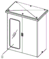
Fig. 1 is a schematic structural diagram of the present invention.
Fig. 2 is an internal schematic view of the present invention.
Fig. 3 is a schematic view of an air conditioner installation area.
Fig. 4 is a schematic structural diagram of a top cover of a cabinet.
Fig. 5 is a sectional view of a side wall of the cabinet.
Detailed Description
The technical solution of the present invention will be described clearly and completely through the following detailed description.
As shown in fig. 1-5, the automatic monitoring control cabinet for high-voltage switch of the present invention comprises a cabinet body, a cabinet top cover 2, a grounding block 3 and an observation window 4; the cabinet body is hermetically connected with the cabinet top cover 2; the top cover 2 of the cabinet is formed by sealing and connecting four triangular plate bodies; the top points of the four triangular plate bodies are all positioned in the center of the top cover of the cabinet, and the bottom edges of the four triangular plate bodies form four edges of the top cover of the cabinet; through the arrangement of the cabinet top cover structure, rainwater cannot cause accumulated water. Can effectually prevent and treat that the rainwater gets into the switch board internally, improve security and reliability of using greatly. Preferably, the peripheral edge of the top cover of the cabinet extends out of the cabinet body.
The top cover of the cabinet of the utility model is internally provided with a heat dissipation channel 21; a filter screen 22 is arranged in the heat dissipation channel 21. The top cover of the cabinet comprises a cover body and a movable body 23 arranged below the cover body; the cover body is formed by sealing and connecting four triangular plate bodies; the triangular plate body comprises an upper plate body 24 and a lower plate body 25 which are arranged in parallel and fixedly connected; a heat dissipation channel 21 is arranged between the upper plate body 24 and the lower plate body 25; the lower-layer plate body is also provided with a heat dissipation hole 26 connected with the heat dissipation channel; the lower plate body is also internally provided with a cavity 27 communicated with the heat dissipation holes; a movable body 23 is arranged in the cavity; the movable body 23 is mounted in the cavity 27 of the lower plate body through a spring 28, the lifting of the movable body is controlled by an electromagnet 30, and an iron block 29 which can be adsorbed by the electromagnet is arranged on the movable body.
The internal temperature sensor that is provided with of cabinet, the switch board is opened according to the temperature control air conditioner of temperature sensor monitoring, also controls electro-magnet 30, removes through electro-magnet control fly leaf, closes the louvre or opens.
The outer edge of the upper-layer plate body is provided with a slope. Is convenient for rain water to drain.
The interior of the cabinet body is divided into a left chamber and a right chamber; the left chamber is a control chamber; a display for displaying the running state and an electric operating element for controlling the whole cabinet body are arranged in the left chamber; an observation window is arranged on the cabinet door of the left chamber; the rear side of the left chamber is provided with a mounting plate and a terminal groove for wiring of the left chamber and the right chamber; the right chamber is provided with an optical fiber box and an intelligent terminal; and an electrical cabinet heat dissipation air conditioner is arranged on the cabinet door plate of the right chamber.
The cabinet body of the utility model is a sealing structure; the door plates on the periphery of the cabinet body are of heat insulation structures; the peripheral door plate of the cabinet body is formed by a three-layer structure and comprises an outer layer plate body 11, a middle heat insulation material layer 12 and an inner layer plate body 13; the outer-layer plate body and the outer-layer plate body are hermetically connected to form a door panel shell with a cavity; the heat insulation material layer is arranged in the cavity of the door panel shell. The heat-insulating material uses flame-retardant rubber sponge, and can insulate heat, prevent sunlight, prevent fire and retard flame.
Set up the observation window on the cabinet door of rack body, can conveniently patrol equipment operation conditions.
The outside of the cabinet body of the utility model is provided with a grounding block 3; the grounding block 3 is used for being connected with a ground rod; can bring reliable insulation for high-voltage equipment.
An air conditioner 1 is installed inside the cabinet body. The adjustable temperature has the advantages of effectively reducing the heat of electrical elements, avoiding accidents, adjusting the temperature and the humidity in the control cabinet and improving the internal environment of the equipment.
The utility model discloses a be provided with rings device on the rack top cap, the transportation of being convenient for.
The above-mentioned embodiments are only described as the preferred embodiments of the present invention, and are not intended to limit the concept and scope of the present invention, and the technical content of the present invention, which is claimed by the present invention, is fully recorded in the technical claims.
Claims (4)
1. High tension switchgear automatic monitoring switch board, its characterized in that: the cabinet comprises a cabinet body, a cabinet top cover, a grounding block and an observation window; the cabinet body is hermetically connected with the cabinet top cover; the top cover of the cabinet is formed by sealing and connecting four triangular plate bodies; the top points of the four triangular plate bodies are all positioned in the center of the top cover of the cabinet, and the bottom edges of the four triangular plate bodies form four edges of the top cover of the cabinet;
the cabinet body is a sealing structure; the door plates on the periphery of the cabinet body are of heat insulation structures;
the outer side of the cabinet body is provided with a grounding block; the grounding block is used for being connected with a ground rod;
an air conditioner is arranged in the cabinet body;
a heat dissipation channel is arranged in the top cover of the cabinet; a filter screen is arranged in the heat dissipation channel;
the outer edge of the upper-layer plate body of the top cover of the cabinet is provided with a slope.
2. The automatic monitoring control cabinet for the high-voltage switch according to claim 1, characterized in that: the interior of the cabinet body is divided into a left chamber and a right chamber; the left chamber is a control chamber; a display for displaying the running state and an electric operating element for controlling the whole cabinet body are arranged in the left chamber; an observation window is arranged on the cabinet door of the left chamber; the rear side of the left chamber is provided with a mounting plate and a terminal groove for wiring of the left chamber and the right chamber; the right chamber is provided with an optical fiber box and an intelligent terminal; and an electrical cabinet heat dissipation air conditioner is arranged on the cabinet door plate of the right chamber.
3. The automatic monitoring control cabinet for the high-voltage switch according to claim 1, characterized in that: and a lifting ring device is arranged on the top cover of the machine cabinet.
4. The automatic monitoring control cabinet for the high-voltage switch according to claim 1, characterized in that: the periphery door plate of the cabinet body is formed by three layers of structures and comprises an outer layer plate body, a middle heat insulation material layer and an inner layer plate body; the outer-layer plate body and the outer-layer plate body are hermetically connected to form a door panel shell with a cavity; the heat insulation material layer is arranged in the cavity of the door panel shell.
Priority Applications (1)
| Application Number | Priority Date | Filing Date | Title |
|---|---|---|---|
| CN201921991866.8U CN211018022U (en) | 2019-11-18 | 2019-11-18 | Automatic monitoring control cabinet for high-voltage switch |
Applications Claiming Priority (1)
| Application Number | Priority Date | Filing Date | Title |
|---|---|---|---|
| CN201921991866.8U CN211018022U (en) | 2019-11-18 | 2019-11-18 | Automatic monitoring control cabinet for high-voltage switch |
Publications (1)
| Publication Number | Publication Date |
|---|---|
| CN211018022U true CN211018022U (en) | 2020-07-14 |
Family
ID=71477348
Family Applications (1)
| Application Number | Title | Priority Date | Filing Date |
|---|---|---|---|
| CN201921991866.8U Active CN211018022U (en) | 2019-11-18 | 2019-11-18 | Automatic monitoring control cabinet for high-voltage switch |
Country Status (1)
| Country | Link |
|---|---|
| CN (1) | CN211018022U (en) |
Cited By (1)
| Publication number | Priority date | Publication date | Assignee | Title |
|---|---|---|---|---|
| CN112366554A (en) * | 2020-09-28 | 2021-02-12 | 广东求精电气有限公司 | Electrical cabinet |
-
2019
- 2019-11-18 CN CN201921991866.8U patent/CN211018022U/en active Active
Cited By (2)
| Publication number | Priority date | Publication date | Assignee | Title |
|---|---|---|---|---|
| CN112366554A (en) * | 2020-09-28 | 2021-02-12 | 广东求精电气有限公司 | Electrical cabinet |
| CN112366554B (en) * | 2020-09-28 | 2022-04-22 | 广东求精电气有限公司 | Electrical cabinet |
Similar Documents
| Publication | Publication Date | Title |
|---|---|---|
| CN207559322U (en) | A kind of 10kV high-tension switch cabinets with earth leakage protective device | |
| CN111431047B (en) | Sealable dustproof power distribution cabinet based on electromagnetic induction principle | |
| CN205657321U (en) | Multi -functional intelligent control switch board | |
| CN211018022U (en) | Automatic monitoring control cabinet for high-voltage switch | |
| CN108631177A (en) | A kind of ring main unit used for open air | |
| CN111509574A (en) | Remote alarm power distribution cabinet | |
| CN205911622U (en) | Closed automatic heat dissipation dehumidification high tension switchgear | |
| CN114744513A (en) | Internet of things smart distribution box for tunnel engineering | |
| CN207039045U (en) | A kind of high-pressure and low-pressure preassembled transformer station | |
| CN207165933U (en) | A kind of comprehensive distribution cabinet that can be monitored in real time | |
| CN202928008U (en) | Supercharged gas interchanger for sulfur hexafluoride in transformer substation | |
| CN205543808U (en) | Intelligent switch cabinet | |
| CN208478878U (en) | A kind of ring network cabinet used for open air | |
| CN211508213U (en) | Electrical safety switch cabinet | |
| CN209544845U (en) | A kind of waterproof distribution box | |
| CN207039039U (en) | A kind of novel high-pressure low pressure preassembled transformer station | |
| CN206947781U (en) | A kind of intelligent grid terminal remote control case | |
| CN207691216U (en) | A kind of moisture-proof high-tension switch cabinet of insect prevention | |
| CN108512055B (en) | Cubical switchboard easy to assemble dismantlement | |
| CN207092928U (en) | A kind of intelligent electric concealed type screen window | |
| CN214798395U (en) | Remove way department and use low pressure electric wiring block terminal | |
| CN217469278U (en) | Dehumidification looped netowrk cabinet convenient to adjust atmospheric pressure | |
| CN212412599U (en) | Prepackage box type transformer substation | |
| CN204030324U (en) | A kind of dust cover of outdoor electric equipment box body ventilating opening | |
| CN212412556U (en) | Novel power distribution cabinet |
Legal Events
| Date | Code | Title | Description |
|---|---|---|---|
| GR01 | Patent grant | ||
| GR01 | Patent grant |