CN211011697U - Indoor gas purification device utilizing hydrogen peroxide heterogeneous advanced oxidation - Google Patents
Indoor gas purification device utilizing hydrogen peroxide heterogeneous advanced oxidation Download PDFInfo
- Publication number
- CN211011697U CN211011697U CN201921668169.9U CN201921668169U CN211011697U CN 211011697 U CN211011697 U CN 211011697U CN 201921668169 U CN201921668169 U CN 201921668169U CN 211011697 U CN211011697 U CN 211011697U
- Authority
- CN
- China
- Prior art keywords
- hydrogen peroxide
- purification
- gas
- chamber
- air
- Prior art date
- Legal status (The legal status is an assumption and is not a legal conclusion. Google has not performed a legal analysis and makes no representation as to the accuracy of the status listed.)
- Active
Links
Images


Abstract
The utility model discloses a purification device for oxidizing indoor air pollutants by utilizing hydrogen peroxide heterogeneous advanced oxidation, which comprises a gas introducing component, a hydrogen peroxide introducing component, a purification chamber and a gas-liquid separation device; the gas introducing assembly comprises a fan and an air pipe; the hydrogen peroxide introducing assembly comprises a hydrogen peroxide liquid storage device and a hydrogen peroxide solution atomizing device; quartz sand cores for placing catalysts are distributed in the purification chamber, and a temperature control heating device is arranged outside the quartz sand cores; indoor gaseous via fan and tuber pipe, in the leading-in purification cavity behind the intercommunication one-level gas distributor, hydrogen peroxide in the hydrogen peroxide liquid storage device gets into the purification cavity after atomizing via hydrogen peroxide solution atomizing device simultaneously, and the leading-in gas-liquid separation of gaseous device after the purification, wherein hydrogen peroxide passes through hydrogen peroxide recovery device and retrieves, and the purified gas is discharged through air-purifying eduction gear. The device has the advantages of no harm and secondary pollution of products, economy, practicality, high efficiency and energy conservation.
Description
Technical Field
The utility model relates to an environmental improvement technique especially relates to an utilize indoor gas purification device of heterogeneous advanced oxidation of hydrogen peroxide.
Background
The World Health Organization (WHO) states that air pollution is defined as polluted outdoor or indoor air organic and inorganic chemical pollutants, including gaseous organic and inorganic chemical pollutants: volatile Organic Compounds (VOCs), carbon monoxide (CO), nitrogen compounds (NOx), sulfur compounds (SOx); pathogen: bacteria, viruses, funguses; particulate matter: solid organic and inorganic pollutants, pathogenic bacteria.
At present, the main approaches and technologies for air purification include photocatalytic oxidation, adsorption purification, low-temperature plasma technology, ozone oxidation and the like. For photocatalytic oxidation, the increase of the concentration of water vapor can cause competitive adsorption with other reactants, so that the reaction is inhibited; and the photocatalytic absorption spectrum is narrow, and the solar energy is not fully utilized. In the adsorption purification method, most of the adsorbents applied to the separation process are single, and the single adsorbent has poor adsorption effect; after the adsorbent is used for a period of time, the adsorption capacity reaches saturation, and the adsorption function is lost or reduced; if the adsorbed organic matters cannot be cleaned in time, bacteria and viruses can be bred under proper conditions, and more serious secondary pollution is caused. The low-temperature plasma technology requires high energy consumption, and the purification efficiency is not high when the concentration of pollutants is high. Ozone may form low molecular weight intermediates in the air purification process, which may pollute the air; a large amount of suspended solid particles generated at the same time may also deteriorate the indoor environment; and ozone is also a recognized environmental pollutant.
For the aspect of air purification, the above purification methods all bring some negative factors, and hydrogen peroxide is a chemical with high utilization rate, has the characteristics of cleanness, high efficiency, no color, no smell and low cost, the vaporized hydrogen peroxide as a gas disinfectant with excellent performance has the advantages of no color and no smell, easy acquisition, low cost, easy recovery, reutilization and the like, the method has good application prospect in the field of eliminating volatile organic pollutants in the air, and in order to better meet the requirement of air purification, the method utilizes the performance characteristic that hydrogen peroxide can rapidly generate a large amount of hydroxyl free radicals with strong oxidizability under the action of a catalyst ferroferric oxide, and the hydroxyl free radicals can react with indoor organic pollutants to generate carbon dioxide and water, the device is designed according to specific reaction purification requirements, and energy conservation and environmental protection are realized on the basis of purifying air.
SUMMERY OF THE UTILITY MODEL
Utility model purpose: to the above-mentioned technical problem that prior art exists, the present application provides an utilize heterogeneous advanced oxidation's of hydrogen peroxide indoor gas purification device.
The technical scheme is as follows: the indoor gas purification device utilizing hydrogen peroxide heterogeneous advanced oxidation comprises a gas introducing assembly, a hydrogen peroxide introducing assembly, a purification chamber and a gas-liquid separation device; wherein the content of the first and second substances,
the gas introducing assembly comprises a fan, an air pipe and a primary gas distributor which are sequentially connected;
the hydrogen peroxide introducing assembly comprises a hydrogen peroxide liquid storage device and a hydrogen peroxide solution atomizing device;
quartz sand cores for placing catalysts are distributed in the purification chamber, and a temperature control heating device is arranged outside the quartz sand cores;
indoor gas is through fan and tuber pipe, and the leading-in purification cavity behind the intercommunication one-level gas distributor is indoor, and hydrogen peroxide in the hydrogen peroxide liquid storage device gets into in the purification cavity after atomizing through hydrogen peroxide solution atomizing device simultaneously, opens control by temperature change heating device, and the leading-in gas-liquid separation of material after the reaction, wherein hydrogen peroxide passes through the recovery of hydrogen peroxide recovery unit, and the purge gas is discharged through air-purifying eduction gear.
Preferably, a secondary gas distributor is further arranged in the purification chamber and used for circularly treating the gas in the purification chamber. The lower part is equipped with a vertical baffle and divides the clean room into two cavities in the clean room, and one of them cavity upper portion is airtight through the second grade gas distributor that sets up between clean room inner wall and baffle, be equipped with the second valve that control gas got into between baffle and the clean room bottom. The quartz sand core penetrates through the partition plate and is subjected to sealing treatment.
As one of the technical solutions, the indoor gas purification device is cylindrical as a whole, the gas introduction assembly is arranged at the top, the purification chamber is located at the middle part, the hydrogen peroxide introduction assembly is arranged close to the inner wall of the purification chamber under the primary gas distributor, and the gas-liquid separation device, the hydrogen peroxide recovery device and the purified air exhaust device are located at the bottom.
Preferably, the quartz sand core is more than two layers and is horizontally arranged in the purification chamber.
Furthermore, the hydrogen peroxide solution storage device is arranged above the hydrogen peroxide solution atomization device and is positioned at the height of about 2/3-7/8 of the purification device body. And a first valve is arranged between the hydrogen peroxide liquid storage device and the hydrogen peroxide solution atomization device, and the hydrogen peroxide solution enters the hydrogen peroxide atomization device through the first valve.
The gas-liquid separation device comprises a condensation part and a centrifugal separation part.
Furthermore, the concentration of the hydrogen peroxide solution is 0.01-0.5 mol/L, the temperature control heating device is a temperature-adjustable heating belt and is wound on the whole outer wall of the purification device, and the working temperature is 50-150 ℃.
Preferably, the concentration of the hydrogen peroxide solution is 0.1-0.4 mol/L, and the working temperature of the temperature control heating device is 70-140 ℃.
Further, the catalyst distributed on the quartz sand core is high-purity ferroferric oxide, and the replacement period is 3-4 years.
The application also discloses a method for purifying indoor air pollutants by using the device, which comprises the following steps:
(1) starting the gas introducing assembly, and allowing indoor gas to enter a purification chamber through a wind pipe and a primary gas distributor under the action of a fan;
(2) starting the hydrogen peroxide introducing assembly, and spraying the hydrogen peroxide solution into the purification chamber through a hydrogen peroxide solution atomizing device;
(3) starting a temperature control heating device, and reacting and purifying the indoor air introduced in the step (1) under the action of the hydrogen peroxide sprayed in the step (2) and the catalyst distributed on the quartz sand core;
(4) and (4) introducing the substance subjected to the reaction in the step (3) into a gas-liquid separation device, wherein hydrogen peroxide is recovered by a hydrogen peroxide recovery device, and purified gas is discharged by a purified air discharge device.
Preferably, in the case where a secondary gas distributor is provided, the following steps are added between step (2) and step (3): and a second valve for controlling gas to enter is arranged between the opening partition plate and the bottom of the purification chamber, and the secondary gas distributor is opened, so that the reactant in the purification chamber can be circularly purified through the secondary gas distributor.
In this application, the first valve between hydrogen peroxide liquid storage device and the hydrogen peroxide solution atomizing device, the second valve between baffle in the purification chamber and the purification chamber bottom is the solenoid valve, opens or closes through electric current access or disconnection control valve.
The device utilizes the heterogeneous advanced oxidation's of hydrogen peroxide indoor air pollutant purifier to use the heterogeneous advanced oxidation of hydrogen peroxide to produce high active hydroxyl free radical, reduces the volatile organic pollutants VOCs's in the air content to guarantee the air quality, guarantee health and safety, the harmless no secondary pollution of product simultaneously, purifying process is energy-efficient.
The component structures, or the positional relationship or the connection relationship between the components, which are not described in the present application, can be implemented by any conventional technique.
Has the advantages that: compared with the prior art, the method has the following advantages: (1) the gas-liquid separation device and the hydrogen peroxide recovery device eliminate residual hydrogen peroxide in primary air purification, thereby avoiding secondary pollution to indoor environment; (2) the hydrogen peroxide solution can quickly generate hydroxyl radicals with strong oxidizing property, oxidize organic pollutants into water and carbon dioxide, have no secondary pollution and simultaneously meet the required air purification requirement; (3) the arrangement of the multi-layer quartz sand core improves the contact effect of reactants and a catalyst, so that the reaction is more sufficient, and the purification efficiency is improved; (4) the heating temperature controller can accurately keep the appropriate temperature required by the purification reaction, and ensure the temperature environment of the reaction system; (5) the arrangement of the hydrogen peroxide atomization device can change the liquid hydrogen peroxide solution into a gaseous state through an atomization technology, thereby increasing the reaction area and realizing the effect of improving the purification efficiency; (6) compared with the similar catalyst, the selected catalyst ferroferric oxide has higher application value, low metal ion percolation rate, easy separation, no secondary pollution, low price, wide source, ideal catalytic effect and strong economy.
Drawings
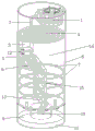
FIG. 1 is a schematic view of the purification apparatus of the present application;
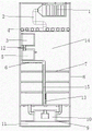
FIG. 2 is a perspective view of the purification apparatus of the present application in half section;
FIG. 3 is a plan view of a half section of the purification apparatus of the present application;
FIG. 4 is a schematic view of the blower connection of the purification apparatus of the present application;
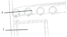
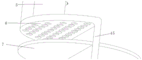
FIG. 5 is a partial enlarged view of the primary gas distributor and the hydrogen peroxide solution storage device of the purification apparatus of the present application;
FIG. 6 is an enlarged view of a portion of a secondary gas distributor of the purification apparatus of the present application;
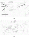
FIG. 7 is a schematic structural diagram of the first valve 12 of the purification apparatus of the present application, wherein (1) is in a closed state and (2) is in an open state;
FIG. 8 is a schematic view of the second valve 13 of the purification apparatus of the present application, which is (1) in an open state and (2) in a closed state;
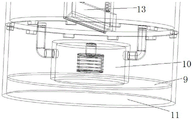
FIG. 9 is an enlarged view of a portion of the lower end of the purification apparatus of the present application.
Among them are: 1. a fan; 2. an air duct; 3. a hydrogen peroxide liquid storage device; 4. a primary gas distributor; 5. a hydrogen peroxide solution atomizing device; 6. a secondary gas distributor; 7. a quartz sand core; 8. a temperature-controlled heating device; 9. a purified air discharge device; 10. a gas-liquid separation device; 11. a hydrogen peroxide recovery unit; 12. a first valve; 13 a second valve; 14 a decontamination chamber; 15 vertical partition plates; 16 valve seats, 17 spring, 18 closure member, 19 solenoid.
Detailed Description
The present application will now be described in further detail with reference to the accompanying drawings and specific examples.
Example 1
As shown in fig. 1, 2 and 3, the indoor air pollutant purification device utilizing hydrogen peroxide heterogeneous advanced oxidation integrally has a cylindrical barrel body, a hole facilitating air entering is formed in a top cover of the device, and the purification device is sequentially provided with: the device comprises a fan 1, an air pipe 2, a primary gas distributor 4, a hydrogen peroxide liquid storage device 3, a hydrogen peroxide solution atomizing device 5, a secondary gas distributor 6, a quartz sand core 7, a temperature control heating device 8, a purified air discharging device 9, a gas-liquid separating device 10 and a hydrogen peroxide recovery device 11. The connection relationship inside the purification device is as follows: the fan 1, the air pipe 2 and the primary gas distributor 4 are bonded with each other, as shown in fig. 4, the fan 1 is screwed with a hole of a top cover of the device, and the air pipe 2 and the primary gas distributor 4 are suspended on the upper part of the device in bonding. The hydrogen peroxide liquid storage device 3 and the hydrogen peroxide solution atomization device 5 are in screwed connection through a straight pipe, the hydrogen peroxide liquid storage device 3 is arranged close to the wall surface of the inner cavity of the purification device and communicated with the hydrogen peroxide solution atomization device 5, and a first valve 12 is arranged between the hydrogen peroxide liquid storage device 3 and the hydrogen peroxide solution atomization device 5; the secondary gas distributor 6 is close to the hydrogen peroxide solution atomization device 5, a purification chamber 14 in the middle of the purification device body is divided into two parts through a vertical partition plate 15, and a second valve 13 is arranged between the vertical partition plate 15 and the bottom of the purification chamber 14.
And the temperature control heating device 8 is wound and fixed on the periphery of the middle quartz sand core 7 on the outer wall of the device. As shown in fig. 9, the purified air discharge means 9 is adhered to the lower floor of the purification chamber 14. The upper ceiling of the gas-liquid separator 10 is bonded to the lower floor of the clean chamber 14, and the lower floor of the clean air discharger 9 is bonded to the upper ceiling of the hydrogen peroxide recovery device 11. The hydrogen peroxide recovery device 11 is clamped at the bottom of the device except for the top plate at the upper part. The hydrogen peroxide remaining solution is stored in the hydrogen peroxide recovery device 11. And catalyst high-purity ferroferric oxide is placed on the quartz sand core 7.
Referring to fig. 5, the primary air distributor 4 is a surrounding coil fine-hole type air distributor, and the air of the pollution source is uniformly dispersed under the action of the primary air distributor 4. As shown in fig. 6, the secondary gas distributor 6 is a semicircular plate-shaped fine hole type gas distributor.
The first valve 12 and the second valve 13 are solenoid valves, and as shown in fig. 7, the first valve 12 is initially in a closed state, when the current is applied, the closing member 18 is pushed out by the electromagnetic force of the right solenoid coil 19, the valve is opened, when the current is not applied, the electromagnetic force disappears, the closing member returns to the initial position valve seat 16 by the elastic action of the spring 17, and the valve is closed. As shown in fig. 8, the second valve 13 between the partition and the bottom of the purification chamber is initially in a power-off closed state, when the power is off, the electromagnetic force of the electromagnetic coil 19 disappears, the spring 17 presses the closing member 18 against the valve seat 16, the second valve 13 is closed and can be manually opened as required to control the primary purified gas to pass through the secondary gas distributor 6, the air is primarily purified in the purification chamber on the right side in the figure, when the indoor gas needs to be secondarily purified, the second valve 13 is energized, the electromagnetic coil 19 generates the electromagnetic force to lift the closing member 18 from the valve seat 16, the second valve 13 is opened to enable the primary purified gas to pass through the secondary gas distributor 6, and the gas is uniformly distributed and then reacts in the purification chamber.
Example 2
A method for purifying indoor air pollutants using the apparatus of example 1, comprising the steps of:
indoor air that contains organic volatile pollutant is earlier by 1 suction of fan, through connecting tuber pipe 2, lets in one-level gas distributor 4, and device body inner chamber left side is equipped with a hydrogen peroxide and deposits liquid device 3, opens first valve 12, and the liquid hydrogen peroxide of certain concentration flows into under the action of gravity and deposits hydrogen peroxide solution atomizing device 5 of liquid device lower part, and through the effect, gaseous phase hydrogen peroxide homodisperse to device body inner chamber in, the equipartition air intensive mixing who gets into with the top reacts. The outside of the device body is wound with a temperature control heating device 8, specifically a temperature control heating belt, mixed working medium passes through more than two layers of quartz sand cores 7 bearing ferroferric oxide catalysts at the temperature of 50-150 ℃ in a heating state, gas-phase hydrogen peroxide contacts the surfaces of the catalysts and reacts at the three-phase joint, the mixed working medium is rapidly decomposed to generate high-concentration hydroxyl radicals, further, the hydroxyl radicals with extremely strong reactivity can complete oxidation reaction in extremely short time, volatile organic pollutants in the air are oxidized into carbon dioxide and water to generate primary purified air, the obtained air enters a gas-liquid separation device 10, the primary purified air is separated, the air is discharged back to the air through a purified air discharge device 9, and the separated liquid enters a hydrogen peroxide recovery device 11 to complete recovery processing. Through experiments, the primary purification rate reaches 98.4%.
The secondary gas distributor can be selectively opened, if air with higher cleanliness needs to be obtained, the purification rate is improved, the second valve 13 is electrified, the electromagnetic coil generates electromagnetic force to lift the closing part from the valve seat, so that the second valve 13 is opened, the primary purified air enters the left side conduit under the action of pressure and reaches the semi-circular plate-shaped fine-hole type gas distributor, under the action of the secondary gas distributor 6, a small amount of hydrogen peroxide carried in the primary purified air is fully utilized in a secondary purification system to carry out purification reaction on the surface of the catalyst, secondary purification is completed, the obtained air enters the gas-liquid separation device, the purified air obtained through centrifugal separation is discharged from the small holes, and the recovered hydrogen peroxide residual liquid flows into the lower collection device, so that the separation treatment of the secondary purified air is realized. Thereby achieving the design requirements.
Wherein, the heating temperature is controlled between 50 ℃ and 150 ℃, the specific temperature is matched with the flow of air, no obvious liquid drop exists, and no condensation exists on the catalyst. Under the condition of the temperature, the hydrogen peroxide contacts the surface of the catalyst and is rapidly decomposed to generate hydroxyl free radicals, and the hydroxyl free radicals with extremely strong reaction activity can complete oxidation reaction in a very short time to oxidize volatile organic pollutants in the air into carbon dioxide and water. Secondly, the air flow velocity of the air sucked by the fan is very fast, and in order to ensure the full occurrence of the reaction, a surrounding coil pipe fine hole type gas distributor is designed, and the air flow velocity is slowed down by utilizing the longer physical length in a certain area, the rotation angle of the coil pipe, the local resistance and the frictional resistance in the pipe and small holes uniformly distributed at the bottom of the pipe, so that the air flow is uniformly dispersed in the device, and the reaction area is increased.
The power of the device in the reaction process can be provided by the gas flow pressure without an external power device.
Meanwhile, in the use process of most catalysts, the catalytic efficiency is gradually reduced due to the reasons of reduction of activity and selectivity, increase of bed pressure drop caused by particle crushing and the like, so that the catalytic process is influenced, and the service life is short. The ferroferric oxide has strong magnetism, is easy to separate, has high reuse rate and long service life, is replaced once in about 3-4 years, and has good economic benefit. Based on comparative experiments, we have collected the following data:


therefore, the optimal purification range is achieved under the conditions that the concentration is 0.1-0.4 mol/L and the temperature is 70-140 ℃, the reaction can be efficient compared with other conditions in terms of air purification efficiency, and the range can be properly enlarged according to specific purification requirements so as to achieve the expected purpose.
Example 3
The concentration of the hydrogen peroxide used by the device is 0.01-0.5 mol/L, the hydrogen peroxide sold in the market can reach the requirement after being diluted by 20-1000 times (30% concentration), namely the benefit is at least 20 times, the hydrogen peroxide with the concentration of 0.1 mol/L is taken as an example, the same purification effect is achieved compared with active carbon, the cost can be reduced by 5-20%, from the aspect of purification efficiency, the formaldehyde and the o-xylene are taken as an example, the purification efficiency can reach 65-75% after 2 hours, and can reach more than 85% after 4 hours, for the o-xylene, the purification efficiency can reach 65-75% after 3 hours, and can reach more than 85% after 6 hours.
When 0.1 mol/L hydrogen peroxide solution is selected for purification at 110 ℃, the consumption of hydrogen peroxide and the consumption of activated carbon are compared as follows when the same purification effect is achieved:

as shown in the above table, the use of the hydrogen peroxide solution can reduce the cost by 5-20%.
The following table shows the comparison of the purification efficiency of hydrogen peroxide for purifying formaldehyde and o-xylene in air at different purification times:

Claims (9)
1. an indoor gas purification device utilizing hydrogen peroxide heterogeneous advanced oxidation is characterized by comprising a gas introducing assembly, a hydrogen peroxide introducing assembly, a purification chamber and a gas-liquid separation device (10); wherein the content of the first and second substances,
the gas introducing assembly comprises a fan (1), an air pipe (2) and a primary gas distributor (4) which are connected in sequence;
the hydrogen peroxide introducing assembly comprises a hydrogen peroxide liquid storage device (3) and a hydrogen peroxide solution atomizing device (5);
quartz sand cores (7) for placing catalysts are distributed in the purification chamber, and a temperature control heating device (8) is arranged outside the quartz sand cores (7);
indoor gas is through fan (1) and tuber pipe (2), in the leading-in purification cavity behind intercommunication one-level gas distributor (4), in hydrogen peroxide in the hydrogen peroxide liquid storage device (3) enters into the purification cavity after atomizing through hydrogen peroxide solution atomizing device (5) simultaneously, open control by temperature change heating device (8), the leading-in gas-liquid separation device of material (10) after the reaction, wherein hydrogen peroxide passes through hydrogen peroxide recovery unit (11) and retrieves, the purge gas passes through air-purifying eduction gear (9) and discharges.
2. Purification device according to claim 1, wherein a secondary gas distributor (6) is arranged in the purification chamber for cyclically treating the gas in the purification chamber.
3. The purification apparatus according to claim 1, wherein the indoor gas purification apparatus is cylindrical as a whole, the gas introduction assembly is provided at the top, the purification chamber is located at the middle, the hydrogen peroxide introduction assembly is provided next to the inner wall of the purification chamber under the primary gas distributor (4), and the gas-liquid separation apparatus (10), the hydrogen peroxide recovery apparatus (11), and the purified air discharge apparatus (9) are located at the bottom.
4. The purification apparatus according to claim 1, wherein the quartz sand core (7) has two or more layers and is horizontally disposed in the purification chamber.
5. A purification apparatus according to claim 2, wherein a vertical partition is provided in the lower and middle part of the purification chamber to divide the purification chamber into two chambers, wherein the upper part of one chamber is sealed by a secondary gas distributor (6) provided between the inner wall of the purification chamber and the partition, and a second valve (13) is provided between the partition and the bottom of the purification chamber to control the gas entering the chamber.
6. The purification apparatus according to claim 1, wherein the hydrogen peroxide solution storage device (3) is disposed above the hydrogen peroxide solution atomization device (5) at a height of about 2/3-7/8.
7. The purification apparatus according to claim 1, wherein the concentration of the hydrogen peroxide solution is 0.01 to 0.5 mol/L.
8. The purification device according to claim 1, wherein the temperature-controlled heating device (8) is a temperature-adjustable heating belt which is wound on the whole outer wall of the purification device and has an operating temperature of 50-150 ℃.
9. The purification device according to claim 1, wherein the catalyst is high-purity ferroferric oxide, and the replacement period is 3-4 years.
Priority Applications (1)
| Application Number | Priority Date | Filing Date | Title |
|---|---|---|---|
| CN201921668169.9U CN211011697U (en) | 2019-10-08 | 2019-10-08 | Indoor gas purification device utilizing hydrogen peroxide heterogeneous advanced oxidation |
Applications Claiming Priority (1)
| Application Number | Priority Date | Filing Date | Title |
|---|---|---|---|
| CN201921668169.9U CN211011697U (en) | 2019-10-08 | 2019-10-08 | Indoor gas purification device utilizing hydrogen peroxide heterogeneous advanced oxidation |
Publications (1)
| Publication Number | Publication Date |
|---|---|
| CN211011697U true CN211011697U (en) | 2020-07-14 |
Family
ID=71467639
Family Applications (1)
| Application Number | Title | Priority Date | Filing Date |
|---|---|---|---|
| CN201921668169.9U Active CN211011697U (en) | 2019-10-08 | 2019-10-08 | Indoor gas purification device utilizing hydrogen peroxide heterogeneous advanced oxidation |
Country Status (1)
| Country | Link |
|---|---|
| CN (1) | CN211011697U (en) |
Cited By (3)
| Publication number | Priority date | Publication date | Assignee | Title |
|---|---|---|---|---|
| CN110779117A (en) * | 2019-10-08 | 2020-02-11 | 南京师范大学 | Indoor gas purification device and method by utilizing hydrogen peroxide heterogeneous advanced oxidation |
| CN112762555A (en) * | 2020-12-31 | 2021-05-07 | 成都赋阳技术开发有限公司 | Air disinfection and purification device |
| CN110779117B (en) * | 2019-10-08 | 2024-04-30 | 南京师范大学 | Indoor gas purification device and method utilizing heterogeneous advanced oxidation of hydrogen peroxide |
-
2019
- 2019-10-08 CN CN201921668169.9U patent/CN211011697U/en active Active
Cited By (3)
| Publication number | Priority date | Publication date | Assignee | Title |
|---|---|---|---|---|
| CN110779117A (en) * | 2019-10-08 | 2020-02-11 | 南京师范大学 | Indoor gas purification device and method by utilizing hydrogen peroxide heterogeneous advanced oxidation |
| CN110779117B (en) * | 2019-10-08 | 2024-04-30 | 南京师范大学 | Indoor gas purification device and method utilizing heterogeneous advanced oxidation of hydrogen peroxide |
| CN112762555A (en) * | 2020-12-31 | 2021-05-07 | 成都赋阳技术开发有限公司 | Air disinfection and purification device |
Similar Documents
| Publication | Publication Date | Title |
|---|---|---|
| CN204478340U (en) | A kind of regenerative air cleaning system | |
| CN108568213B (en) | Bench type laboratory air pollutant removing machine | |
| CN101314101B (en) | Air purification method combined of adsorption and heat catalytic oxidation regeneration in situ | |
| CN104383812B (en) | VOCs low-temperature plasma multiple treating system | |
| CN201684212U (en) | Air sterilization purifier | |
| CN202778234U (en) | Combined-type organic waste gas treatment device | |
| CN101972573A (en) | Adsorption-degradation filter element and air purifier using same | |
| CN103272445A (en) | Air purification equipment | |
| CN211011697U (en) | Indoor gas purification device utilizing hydrogen peroxide heterogeneous advanced oxidation | |
| CN2603697Y (en) | Washing type photocatalysis air purifier | |
| CN202460468U (en) | Photocatalytic organic waste gas purifier | |
| CN105983334B (en) | A kind of foul gas cleaning treatment system and its processing method | |
| CN207012785U (en) | A kind of micro-wave nonpolar photooxidation, plasma, photocatalysis combined exhaust gas governing system | |
| CN206082107U (en) | Industry organic waste gas purification device | |
| CN110779117A (en) | Indoor gas purification device and method by utilizing hydrogen peroxide heterogeneous advanced oxidation | |
| CN201871296U (en) | Adsorptive degradation filter element and air purification device using the filter element | |
| CN110779117B (en) | Indoor gas purification device and method utilizing heterogeneous advanced oxidation of hydrogen peroxide | |
| CN114452977B (en) | Dual-functional material capable of circularly integrating and simultaneously adsorbing and catalyzing to remove VOCs under low temperature condition, and preparation method and application thereof | |
| CN102778010A (en) | Self-control system of air purifying device | |
| CN206739460U (en) | A kind of air purifier | |
| CN202113732U (en) | Air purifier | |
| CN111729508B (en) | Mixed induced flow spraying deodorization device | |
| CN112774381A (en) | Fresh air purification system and equipment | |
| CN210332183U (en) | VOC adsorption concentration catalytic combustion system | |
| CN204043071U (en) | High-efficiency environment friendly air cleaner |
Legal Events
| Date | Code | Title | Description |
|---|---|---|---|
| GR01 | Patent grant | ||
| GR01 | Patent grant |