CN211005073U - Glass raw material feeder - Google Patents
Glass raw material feeder Download PDFInfo
- Publication number
- CN211005073U CN211005073U CN201922072800.5U CN201922072800U CN211005073U CN 211005073 U CN211005073 U CN 211005073U CN 201922072800 U CN201922072800 U CN 201922072800U CN 211005073 U CN211005073 U CN 211005073U
- Authority
- CN
- China
- Prior art keywords
- glass raw
- shovel
- rod
- eccentric
- board
- Prior art date
- Legal status (The legal status is an assumption and is not a legal conclusion. Google has not performed a legal analysis and makes no representation as to the accuracy of the status listed.)
- Active
Links
Images


Abstract
The utility model discloses a glass raw material charging machine, which relates to the technical field of glass preparation, and comprises a stock bin, a material pushing device and a driving device; the discharge gate is seted up to the feed bin bottom, and blevile of push includes pushing away the material shovel, and drive arrangement with push away the material shovel and be connected, glass raw materials from the feed bin bottom on pushing away the material shovel, drive arrangement drive pushing away the material shovel and be swing motion for promote glass raw materials to get into the smelting kiln pond from the feed bin bottom. The beneficial effects of the utility model reside in that: in the feeding process, the glass raw materials are not required to be lifted to the upper part of the glass melting cellar inlet by a conveying belt, so that the glass raw materials can be prevented from being attached to the conveying belt.
Description
Technical Field
The utility model relates to a glass preparation technical field, concretely relates to glass raw materials feeder.
Background
Glass originally originated in france in the 16 th century, and began to be adopted gradually in some countries in the 19 th century, and various glass products produced by using glass technology have been widely used all over the world by the 20 th century. Originally, glass has the characteristics of light transmission and opacity, and is widely applied to the fields of home furnishing, decoration, buildings and the like, along with the gradual enhancement of environmental awareness of human beings, the green energy solar industry rapidly rises, glass matched with the green energy solar industry becomes the sunward industry, and glass production lines at home and abroad are rapidly spread like spring bamboo shoots after rain.
Glass is called "glass" because molten glass is formed by pressing and spreading between upper and lower rolls of a calender, and the forming process thereof is called a calendering method. The production process of the glass is the same as that of flat glass, firstly, various powdery raw materials meeting the production requirements are sent into a proportioning bin, the various raw materials are weighed according to a designed proportioning table under the control of a computer, mixed by a mixer to prepare a batch, then the qualified batch is sent into a kiln head bin through a belt conveyor, the batch in the kiln head bin is sent into a glass melting kiln by a feeder, uniform glass liquid is obtained through the processes of melting, clarifying, homogenizing, cooling and the like within the temperature range of 1450-1580 ℃, and the glass liquid enters a forming chamber to be formed after the viscosity of the glass reaches the appropriate forming viscosity. In the process, production raw materials are required to be continuously fed into a melting furnace, the internal temperature of the melting furnace of a glass production line is over thousands of degrees, personnel cannot approach the melting furnace for a long time at all, and the thickness of the fed raw material layer and the feeding speed are required to be kept as uniform as possible in the production process, so that the work cannot be finished by utilizing manpower at all, and feeding equipment is required to replace the manpower for finishing the work.
Patent CN201120059264.6 discloses a glass material conveying device, which includes a power device, a frame, a driving roller, and a conveying belt, and is characterized in that only one supporting roller is arranged on each section of the lower portion of the conveying belt along the conveying direction, and the supporting rollers are in a cylindrical shape with two end portions having a diameter larger than the middle portion, i.e. the middle portion of the supporting roller is concave.
Because the temperature near the glass melting furnace is higher, the glass raw materials are lifted to the upper part of the glass melting furnace inlet by the conveyer belt, and the phenomenon that the raw materials are attached to the conveyer belt easily occurs in the conveying process, so that the product quality is influenced.
SUMMERY OF THE UTILITY MODEL
The utility model aims to solve the technical problem that the phenomenon that the raw materials are attached to the conveyer belt easily appears in current glass raw materials conveyor, provide a glass raw materials feeder.
The utility model discloses a following technical means realizes solving above-mentioned technical problem:
the utility model provides a glass raw material charging machine, which comprises a stock bin, a material pushing device and a driving device; the discharge gate is seted up to the feed bin bottom, blevile of push is including pushing away the material shovel, drive arrangement with push away the material shovel and be connected, the glass raw materials falls on pushing away the material shovel from the feed bin bottom, drive arrangement drive pushes away the material shovel and is swing motion for promote the glass raw materials and get into the smelting kiln pond from the feed bin bottom.
The working principle is as follows: the glass raw materials are placed in the storage bin, fall on the material pushing shovel, the driving unit is started, and the driving unit drives the material pushing shovel to swing, so that the glass raw materials are pushed to enter the melting furnace pool from the bottom end of the storage bin.
Has the advantages that: the glass raw materials are directly fed into the melting furnace tank from the bottom end of the storage bin through the material pushing shovel, the glass raw materials are not required to be lifted to the position above the glass melting furnace inlet through the conveying belt, and the glass raw materials can be prevented from being attached to the conveying belt.
Preferably, the feed bin is located the board, the board includes first board and second board, the axis of first board is perpendicular with the axis of second board, first board is located the tip of second board, the material pushing opening has been seted up to the second board, material pushing opening corresponds with the discharge gate of feed bin.
Preferably, the one end of pushing shovel runs through and pushes away the material mouth, the one end of pushing shovel is located feed bin discharge gate below, the other end of pushing shovel is located pushes away material mouthful top, drive arrangement drive pushing shovel is in pushing away the material mouthful interior swing motion that is.
Preferably, the cross section of the material pushing shovel is arc-shaped.
Preferably, the pushing device further comprises a fixing mechanism, the fixing mechanism comprises even number of connecting rods, one end of each connecting rod is connected with the side wall of the material pushing shovel, the other end of each connecting rod is rotatably connected with the first machine table, and the connecting rods are symmetrically arranged relative to the material bin.
Preferably, fixed establishment still includes bearing frame, bearing and transmission shaft, the bearing frame is located the roof of first board, the bearing is installed in the bearing frame, the number of bearing frame and bearing is two respectively, the transmission shaft is located between the bearing frame, and installs in the bearing, the one end of connecting rod is passed through the bearing and is connected with first board rotation.
Preferably, the driving device comprises a driving mechanism and a transmission mechanism; the driving mechanism comprises a motor; the transmission mechanism comprises an eccentric adjusting unit and a transmission unit, wherein the eccentric adjusting unit is respectively connected with the motor and the transmission unit and used for pushing the material pushing shovel to do swinging motion in the material pushing opening.
Preferably, the eccentric adjusting unit comprises an eccentric seat, a fixing rod, a first screw, an eccentric shaft and a fastener, wherein a groove is formed in one side of the eccentric seat, the fixing rod is arranged on the other side of the eccentric seat, one end of the fixing rod is connected with the eccentric seat, and the other end of the fixing rod is connected with the motor;
one end of the eccentric shaft is positioned in the groove, a threaded hole is formed in the eccentric shaft, one end of the first screw rod is screwed into the threaded hole of the eccentric shaft and penetrates through the eccentric seat, the other end of the first screw rod extends out of the other end of the eccentric seat, and fasteners are arranged at two ends of the first screw rod and used for fixing the first screw rod on the eccentric seat.
Has the advantages that: the material pushing amplitude of the material pushing shovel is adjusted by adjusting the eccentric amount of the eccentric adjusting unit.
Preferably, the fastener includes baffle and fastening nut, the baffle includes first baffle and second baffle, first baffle and second baffle are located the both ends of eccentric seat respectively, first baffle is passed to the one end of first screw rod, the other end of first screw rod passes the second baffle, the both ends of first screw rod are equipped with lock nut respectively.
Preferably, the transmission unit comprises a second screw, two rod end joint bearings, a rotating shaft and a locking nut, the number of the rod end joint bearings is two, each rod end joint bearing comprises a first rod end joint bearing and a second rod end joint bearing, the two ends of the second screw are respectively provided with the rod end joint bearings, the first rod end joint bearings are connected with the eccentric shaft, and the second rod end joint bearings are rotatably connected with the end part of the material pushing shovel.
Preferably, the glass raw material feeder further comprises a cooling device, and the cooling device comprises a first machine cooling unit;
the first machine table is hollow, the cooling unit comprises a first water inlet and a first water outlet, and the first water inlet and the first water outlet are both located on the first machine table.
Preferably, a first water inlet pipe is arranged on the first water inlet, and a first water outlet pipe is arranged on the first water outlet.
Preferably, the cooling device further comprises a second machine table cooling unit, the second machine table is hollow, the second machine table cooling unit comprises a second water inlet and a second water outlet, and the second water inlet and the second water outlet are both located on the second machine table.
Preferably, a second water inlet pipe is arranged on the second water inlet, and a second water outlet pipe is arranged on the second water inlet.
Preferably, the cooling device further comprises a pushing shovel cooling unit, the pushing shovel cooling unit comprises a third water inlet and a third water outlet, the pushing shovel is hollow, and the third water inlet and the third water outlet are both located on the pushing shovel.
Preferably, a third water inlet pipe is arranged on the third water inlet, and a third water outlet pipe is arranged on the third water inlet.
Has the advantages that: because the charging machine is in a high-temperature environment for a long time, in order to reduce the overall temperature of the charging machine, a first machine cooling unit, a second machine cooling unit and a pushing shovel cooling unit are arranged.
The utility model discloses a theory of operation: adjusting the eccentricity of the eccentricity adjusting unit: loosening screws or bolts on the first baffle and the second baffle, loosening locking nuts at two ends of the first screw, pulling or rotating the first screw, adjusting the position of the eccentric shaft in the groove, so as to change the eccentric amount, fixing the first baffle and the second baffle at two ends of the eccentric seat respectively after the adjustment is completed, screwing the locking nuts in two ends of the first screw, and locking the first screw.
Adjusting the starting position and the ending position of the pushing shovel: rotating rod end joint bearing, increasing the length of second screw through rod end joint bearing to realize the regulation of the initial and final position of material pushing shovel.
Feeding by a glass raw material feeder: starting a speed reducing motor, rotating an output shaft of the speed reducing motor to drive an eccentric adjusting unit to rotate, driving a second screw rod to push a material pushing shovel to swing below a discharge port of a storage bin by taking a connecting rod as a radius, and adjusting the material pushing amplitude of the material pushing shovel by adjusting the eccentric amount of the eccentric adjusting unit;
the glass raw materials are fed from a feed inlet of the storage bin, the fed glass raw materials fall above the material pushing shovel, the gear motor is started to drive the material pushing shovel to swing above the material pushing port, the glass raw materials fall near the melting furnace after the material pushing shovel swings, at the moment, the material pushing shovel swings towards the glass raw materials, so that the glass raw materials are pushed into the melting furnace pool, and the material pushing shovel swings back and forth by taking the connecting rod as a radius, so that the glass raw materials are pushed into the melting furnace pool.
The utility model has the advantages that: the eccentric adjusting unit and the transmission unit are adjusted to achieve the purposes of adjusting the pushing amplitude of the pushing plate and adjusting the starting position and the ending position of the pushing shovel, the position of the glass raw materials falling into the smelting pit pool can be adjusted by adjusting the pushing amplitude and the starting position and the ending position of the pushing shovel, the glass raw materials are prevented from being piled at the same position of the smelting pit pool, the glass raw materials are distributed more uniformly in the smelting pit pool, and the melting of the glass raw materials is accelerated.
In the feeding process, the glass raw materials are not required to be lifted to the upper part of the glass melting cellar inlet by a conveying belt, so that the glass raw materials can be prevented from being attached to the conveying belt.
Drawings
FIG. 1 is a schematic structural view of a glass raw material feeder according to example 1 of the present invention;
FIG. 2 is a schematic structural view of a glass raw material feeder according to another view angle in example 1 of the present invention;
FIG. 3 is a side view of a part of the structure of a glass raw material feeder according to example 1 of the present invention;
FIG. 4 is a side view of a part of the structure of a glass raw material feeder according to example 1 of the present invention;
fig. 5 is a partial schematic structural view of a fixing mechanism in embodiment 1 of the present invention;
fig. 6 is a schematic structural view of an eccentric adjustment unit in embodiment 1 of the present invention;
fig. 7 is a partial schematic structural view of the eccentric adjustment unit and the transmission unit in embodiment 1 of the present invention;
fig. 8 is a schematic structural view of a transmission unit in embodiment 1 of the present invention;
FIG. 9 is a plan view of a glass raw material feeder according to example 2 of the present invention;
FIG. 10 is a schematic structural view of a glass raw material feeder according to example 2 of the present invention;
in the figure: a storage bin 11; a first machine 121; a second machine 122; a pusher shovel 131; a bearing seat 142; a drive shaft 143; a connecting rod 144; a reduction motor 151; a heat shield 152; an eccentric seat 161; a fixing rod 162; a first screw 163; an eccentric shaft 164; a baffle 165; a lock nut 166; a second screw 171; a rod end knuckle bearing 172; a rotating shaft 173; a first water inlet pipe 191; a first outlet pipe 192; a second inlet pipe 201; a second outlet pipe 202; a third water inlet pipe 211; and a third outlet pipe 212.
Detailed Description
To make the purpose, technical solution and advantages of the embodiments of the present invention clearer, the embodiments of the present invention are combined to clearly and completely describe the technical solution in the embodiments of the present invention, and obviously, the described embodiments are some embodiments of the present invention, not all embodiments. Based on the embodiments in the present invention, all other embodiments obtained by a person skilled in the art without creative efforts belong to the protection scope of the present invention.
It will be understood that when an element is referred to as being "secured to" another element, it can be directly on the other element or intervening elements may also be present. When an element is referred to as being "connected" to another element, it can be directly connected to the other element or intervening elements may also be present.
It is noted that, in this document, relational terms such as first and second, and the like, if any, are used solely to distinguish one entity or action from another entity or action without necessarily requiring or implying any actual such relationship or order between such entities or actions. Also, the terms "comprises," "comprising," or any other variation thereof, are intended to cover a non-exclusive inclusion, such that a process, method, article, or apparatus that comprises a list of elements does not include only those elements but may include other elements not expressly listed or inherent to such process, method, article, or apparatus. Without further limitation, an element defined by the phrase "comprising an … …" does not exclude the presence of other identical elements in a process, method, article, or apparatus that comprises the element.
Example 1
A glass raw material feeder is shown in figures 1 and 2 and comprises a storage bin 11, a material pushing device and a driving device; the material pushing device comprises a material pushing shovel 131, the driving device is connected with the material pushing shovel 131, the glass raw materials fall on the material pushing shovel 131 from the bottom end of the storage bin 11, and the driving device drives the material pushing shovel 131 to do swinging motion so as to push the glass raw materials to enter the melting furnace tank from the bottom end of the storage bin 11.
As shown in fig. 3, a feed inlet is formed in the top wall of the storage bin 11, the size of the feed inlet is set according to actual needs, in order to facilitate feeding of the materials into the storage bin 11, the size of the feed inlet is equal to the size of the top wall of the storage bin 11, a discharge outlet is formed in the bottom wall of the storage bin 11, in order to facilitate conveying of the glass materials, the size of the discharge outlet is equal to the size of the bottom wall of the storage bin 11;
as shown in fig. 3, the storage bin 11 is hollow and columnar, the storage bin 11 is formed by enclosing side walls, in order to prevent the glass raw material from being retained and immobilized in the storage bin 11 and cause the added material to flow out, and meanwhile, one side wall of the storage bin 11 is inclined to make the section of the storage bin 11 in a right trapezoid shape by better matching with the material pushing shovel 131; in the glass raw materials got into the smelting cellar pond from feed bin 11, for preventing the wearing and tearing of glass raw materials to feed bin 11, feed bin 11's material was stand wear and tear the material.
As shown in fig. 3 and 4, the bin 11 is fixedly welded on a machine table, which can prevent the bin 11 from being dislocated with the machine table, the machine table is arranged close to the molten cellar pool, the cross section of the machine table is L-shaped, the machine table includes a first machine table 121 and a second machine table 122, the sizes of the first machine table 121 and the second machine table 122 are arranged according to actual needs, the axis of the first machine table 121 is perpendicular to the axis of the second machine table 122, the first machine table 121 is fixedly installed at the end of the second machine table 122, one side of the bin 11 is fixedly installed at the side wall of the first machine table 121, the inclined side wall of the bin 11 is arranged opposite to the first machine table 121, and the second machine table 122 is provided with a material pushing port corresponding to a material outlet of;
as shown in fig. 3, the material pushing device includes a material pushing shovel 131 and a fixing mechanism, the cross section of the material pushing shovel 131 is arc, one end of the material pushing shovel 131 passes through the material pushing opening, one end of the material pushing shovel 131 is located below the material outlet of the storage bin 11, and the other end of the material pushing shovel 131 is located on one side of the inclined side wall of the storage bin 11; the material pushing shovel 131 is formed by welding steel plates, so that the operation time of the material pushing shovel in a high-temperature environment is prolonged;
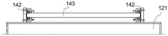
as shown in fig. 5, the fixing mechanism includes two bearing blocks 142, two bearings, a transmission shaft 143, and a connecting rod 144, the bearing blocks 142 are fixedly mounted on the top wall of the first machine 121, each bearing block 142 is provided with a bearing hole, a bearing is mounted in each bearing hole, the two bearing blocks 142 are arranged oppositely, and the two bearings are mounted at two ends of the transmission shaft 143 respectively; the number of the connecting rods 144 is two, the two connecting rods 144 are respectively located at two sides of the storage bin 11, the two connecting rods 144 are symmetrically arranged relative to the storage bin 11, the transmission shaft 143 penetrates through one end of the connecting rods 144, and the other end of the connecting rods 144 is respectively fixedly connected with two sides of the material pushing shovel 131, so that the material pushing shovel 131 can make swinging motion in the material pushing port by taking the connecting rods 144 as a radius; the bearing in this embodiment is a self-aligning roller bearing.
Drive arrangement includes actuating mechanism and drive mechanism, as shown in fig. 2 and fig. 4, actuating mechanism includes gear motor 151, for the steadiness of reinforcing board and convenient change, gear motor 151's diapire mounting panel fixed connection, the mounting panel is through last seting up the screw hole, fix the mounting panel on second board 122 through bolt or screw, for the heat radiation that prevents the smelting kiln pond causes gear motor 151's trouble or reduction life-span, gear motor 151 is close to one side installation heat insulating board 152 in the smelting kiln pond, pack the heat preservation cotton in the heat insulating board 152, heat insulating board 152 is through welding or bolt mounting at the motor lateral wall.
The transmission mechanism comprises an eccentric adjusting unit and a transmission unit; as shown in fig. 6 and 7, the eccentric adjusting unit includes an eccentric seat 161, a fixing rod 162, a first screw 163, an eccentric shaft 164, a baffle 165 and a locking nut 166, one side of the eccentric seat 161 is provided with a groove, the other side of the eccentric seat 161 is fixedly provided with the fixing rod 162, the specific position of the fixing rod 162 is set according to actual requirements, and the fixing rod 162 is fixedly connected with the output shaft of the reduction motor 151;
one end of the eccentric shaft 164 is located in the groove, the eccentric shaft 164 can move back and forth in the groove along the axis of the eccentric shaft 164, a threaded hole is formed in the end of the eccentric shaft 164, one end of the first screw 163 is screwed into the threaded hole of the eccentric shaft 164 and penetrates through the eccentric seat 161, and the other end of the first screw 163 extends out of the other end of the eccentric seat 161;
the baffle 165 comprises a first baffle 165 and a second baffle 165, holes matched with the first screw 163 are formed in the side wall of the first baffle 165 and the side wall of the second baffle 165, the first baffle 165 and the second baffle 165 are respectively located at two ends of the eccentric seat 161, one end of the first screw 163 penetrates through the first baffle 165, the other end of the first screw 163 penetrates through the second baffle 165, the first baffle 165 and the second baffle 165 are provided with threaded holes penetrating through the eccentric seat 161, and the first baffle 165 and the second baffle 165 are fixed at two ends of the eccentric seat 161 through bolts or screws;
two ends of the first screw 163 are respectively provided with a locking nut 166, and the locking nuts 166 are respectively in threaded connection with two ends of the first screw 163; the eccentric adjusting unit in the embodiment can also adopt an eccentric adjusting device in the prior art;
in order to prevent the eccentric shaft 164 from moving, a threaded hole is formed in the side wall of the eccentric seat 161, and a screw or a bolt is installed in the threaded hole, and the screw and the bolt abut against the eccentric shaft 164 to fasten the eccentric shaft 164.
As shown in fig. 8, the transmission unit is located above the end of the material pushing shovel 131, the transmission unit includes a second screw 171, a rod end joint bearing 172 and a rotating shaft 173, two ends of the second screw 171 are respectively provided with an external thread, the number of the rod end joint bearings 172 is two, the transmission unit includes a first rod end joint bearing 172 and a second rod end joint bearing 172, a rod end of the rod end joint bearing 172 is provided with an internal thread, a rod end of the rod end joint bearing 172 is respectively connected with the end of the second screw 171 by a thread, in order to prevent the rod end of the rod end joint bearing 172 from loosening with the second screw 171, the rod end of the rod end joint bearing 172 is locked with the second screw 171 by a nut, the nut and nut mounting manner is the prior art, the bearing end of the first rod end joint bearing 172 is, the connection mode is the prior art, and the bearing end of the second rod end oscillating bearing 172 is rotatably connected with the end of the pushing shovel 131 through a rotating shaft 173.
The working principle of the embodiment is as follows:
adjusting the eccentricity of the eccentricity adjusting unit: the screws or bolts on the first baffle plate 165 and the second baffle plate 165 are loosened, the locking nuts 166 at the two ends of the first screw rod 163 are loosened, the first screw rod 163 is pulled or rotated, the position of the eccentric shaft 164 in the groove is adjusted, so that the eccentric amount is changed, after the adjustment is completed, the first baffle plate 165 and the second baffle plate 165 are fixed at the two ends of the eccentric seat 161 respectively, the locking nuts 166 are screwed into the two ends of the first screw rod 163, and the first screw rod 163 is locked.
Adjustment of the starting and ending positions of the pusher shovel 131: the rod end knuckle bearing 172 is rotated to increase the length of the second screw 171 through the rod end knuckle bearing 172, thereby achieving the adjustment of the starting and ending positions of the material pushing shovel 131.
Feeding by a glass raw material feeder: starting the speed reducing motor 151, rotating an output shaft of the speed reducing motor 151 to drive the eccentric adjusting unit to rotate, driving the second screw 171 to push the material pushing shovel 131 to swing below the discharge port of the storage bin 11 by taking the connecting rod 144 as a radius, and adjusting the material pushing amplitude of the material pushing shovel 131 by adjusting the eccentric amount of the eccentric adjusting unit;
the glass raw materials are fed from a feeding hole of the storage bin 11, the fed glass raw materials fall above the material pushing shovel 131, the speed reducing motor 151 is started to drive the material pushing shovel 131 to swing above a material pushing opening, the glass raw materials fall near the melting furnace after the material pushing shovel 131 swings, at the moment, the material pushing shovel 131 swings towards the glass raw materials, the glass raw materials are pushed into the melting furnace pool, and the material pushing shovel 131 swings back and forth by taking the connecting rod 144 as a radius, so that the glass raw materials are pushed into the melting furnace pool.
The beneficial effects of the embodiment are that: the eccentric adjusting unit and the transmission unit are adjusted to achieve the purposes of adjusting the pushing amplitude of the pushing plate and adjusting the starting position and the ending position of the pushing shovel 131, the position of the glass raw material falling into the smelting pit can be adjusted by adjusting the pushing amplitude and the starting position and the ending position of the pushing shovel 131, the glass raw material is prevented from falling into the same position of the smelting pit, the glass raw material is distributed more uniformly in the smelting pit, and the melting of the glass raw material is accelerated.
In the feeding process, the glass raw materials are not required to be lifted to the upper part of the glass melting cellar inlet by a conveying belt, so that the glass raw materials can be prevented from being attached to the conveying belt.
Example 2
This embodiment is different from embodiment 1 in that: as the feeder is in a high-temperature environment for a long time, in order to reduce the overall temperature of the feeder, as shown in fig. 9, the feeder further includes a cooling device, which includes a first machine table 121 cooling unit, a second machine table 122 cooling unit, and a pushing shovel 131 cooling unit;
The second board 122 is formed by the steel sheet welding, the second board 122 is the cavity form, second board 122 cooling unit includes the second water inlet, the second delivery port, second inlet tube 201 and second outlet pipe 202, the second water inlet is all seted up on second board 122 with the second delivery port, the second water inlet is located one side of second board 122, the second delivery port is located the opposite side of second board 122, second inlet tube 201 is connected with the second water inlet, second outlet pipe 202 is connected with the second delivery port, the cooling water flows from second inlet tube 201 back, from second outlet pipe 202 outflow.
The material pushing shovel 131 is hollow, the cooling unit of the material pushing shovel 131 comprises a third water inlet, a third water outlet, a third water inlet pipe 211 and a third water outlet pipe 212, the third water inlet and the third water outlet are both arranged on the material pushing shovel 131, the third water inlet is located on one side of the material pushing shovel 131, the third water outlet is located on the other side of the material pushing shovel 131, the third water inlet pipe 211 is connected with the third water inlet, the third water outlet pipe 212 is connected with the third water outlet, cooling water flows in from the third water inlet pipe 211 and flows out from the third water outlet pipe 212 after flowing through the whole material pushing shovel 131.
Example 3
This embodiment is different from embodiment 1 in that: in order to prevent the feeder from having faults in the operation process, most faults cannot be eliminated in the working process of the feeder, the pushing shovel 131 needs to stop swinging at a specific position, and then faults are eliminated, so that the problem is solved;
the switch bracket is installed on the second machine table 122, the induction switch is fixedly installed on the switch bracket, the installation mode can be welding or installing the induction switch on the second machine table 122 through bolts, the induction sheet is fixedly installed on the eccentric seat 161, when the position of the induction sheet corresponds to the induction switch, the induction switch receives a signal of the induction sheet, the induction switch transmits the signal to the controller, the controller transmits the signal to the speed reducing motor 151, the motor stops rotating, the speed reducing motor 151 stops rotating, the material pushing shovel 131 stops swinging, and the material pushing shovel 131 stops at a preset position for maintenance.
The positions of the switch bracket and the sensing piece are set according to actual requirements so as to meet the requirement that the material pushing shovel 131 stops swinging at a specific position.
The above embodiments are only used to illustrate the technical solution of the present invention, and not to limit it; although the present invention has been described in detail with reference to the foregoing embodiments, it should be understood by those skilled in the art that: the technical solutions described in the foregoing embodiments may still be modified, or some technical features may be equivalently replaced; such modifications and substitutions do not depart from the spirit and scope of the present invention in its corresponding aspects.
Claims (10)
1. The utility model provides a glass raw material charging machine which characterized in that: comprises a stock bin, a material pushing device and a driving device; the discharge gate is seted up to the feed bin bottom, blevile of push is including pushing away the material shovel, drive arrangement with push away the material shovel and be connected, the glass raw materials falls on pushing away the material shovel from the feed bin bottom, drive arrangement drive pushes away the material shovel and is swing motion for promote the glass raw materials and get into the smelting kiln pond from the feed bin bottom.
2. The glass raw material feeder according to claim 1, characterized in that: the feed bin is located the board, the board includes first board and second board, the axis of first board is perpendicular with the axis of second board, first board is located the tip of second board, the second board has been seted up and has been pushed away the material mouth, it corresponds with the discharge gate of feed bin to push away the material mouth.
3. The glass raw material feeder according to claim 1, characterized in that: the one end of pushing shovel runs through and pushes away the material mouth, the one end that pushes away the material shovel is located feed bin discharge gate below, the other end that pushes away the material shovel is located and pushes away material mouthful top, drive arrangement drive pushes away the material shovel and is swing motion in pushing away the material mouth.
4. The glass raw material feeder according to claim 1, characterized in that: the material pushing device further comprises a fixing mechanism, the fixing mechanism comprises connecting rods, the number of the connecting rods is even, one end of each connecting rod is connected with the side wall of the material pushing shovel, the other end of each connecting rod is rotatably connected with the first machine, and the connecting rods are symmetrically arranged relative to the material bin.
5. The glass raw material feeder according to claim 4, characterized in that: the fixing mechanism further comprises bearing seats, bearings and transmission shafts, the bearing seats are located on the top wall of the first machine table, the bearings are installed in the bearing seats, the number of the bearing seats and the number of the bearings are two respectively, the transmission shafts are located between the bearing seats and installed in the bearings, and one ends of the connecting rods are rotatably connected with the first machine table through the bearings.
6. The glass raw material feeder according to claim 1, characterized in that: the driving device comprises a driving mechanism and a transmission mechanism; the driving mechanism comprises a motor; the transmission mechanism comprises an eccentric adjusting unit and a transmission unit, wherein the eccentric adjusting unit is respectively connected with the motor and the transmission unit and used for pushing the material pushing shovel to do swinging motion in the material pushing opening.
7. The glass raw material feeder according to claim 6, characterized in that: the eccentric adjusting unit comprises an eccentric seat, a fixed rod, a first screw rod, an eccentric shaft and a fastener, wherein one side of the eccentric seat is provided with a groove, the other side of the eccentric seat is provided with the fixed rod, one end of the fixed rod is connected with the eccentric seat, and the other end of the fixed rod is connected with the motor;
one end of the eccentric shaft is positioned in the groove, a threaded hole is formed in the eccentric shaft, one end of the first screw rod is screwed into the threaded hole of the eccentric shaft and penetrates through the eccentric seat, the other end of the first screw rod extends out of the other end of the eccentric seat, and fasteners are arranged at two ends of the first screw rod and used for fixing the first screw rod on the eccentric seat.
8. The glass raw material feeder according to claim 7, characterized in that: the fastener includes baffle and fastening nut, the baffle includes first baffle and second baffle, first baffle and second baffle are located the both ends of eccentric seat respectively, first baffle is passed to the one end of first screw rod, the other end of first screw rod passes the second baffle, the both ends of first screw rod are equipped with lock nut respectively.
9. The glass raw material feeder according to claim 6, characterized in that: the transmission unit comprises a second screw, a rod end joint bearing, a rotating shaft and a locking nut, the number of the rod end joint bearings is two, the rod end joint bearing comprises a first rod end joint bearing and a second rod end joint bearing, the two ends of the second screw are respectively provided with the rod end joint bearing, the first rod end joint bearing is connected with the eccentric shaft, and the second rod end joint bearing is rotatably connected with the end part of the material pushing shovel.
10. The glass raw material feeder according to claim 2, characterized in that: the glass raw material feeder also comprises a cooling device, and the cooling device comprises a first machine cooling unit;
the first machine table is hollow, the cooling unit comprises a first water inlet and a first water outlet, and the first water inlet and the first water outlet are both located on the first machine table.
Priority Applications (1)
| Application Number | Priority Date | Filing Date | Title |
|---|---|---|---|
| CN201922072800.5U CN211005073U (en) | 2019-11-27 | 2019-11-27 | Glass raw material feeder |
Applications Claiming Priority (1)
| Application Number | Priority Date | Filing Date | Title |
|---|---|---|---|
| CN201922072800.5U CN211005073U (en) | 2019-11-27 | 2019-11-27 | Glass raw material feeder |
Publications (1)
| Publication Number | Publication Date |
|---|---|
| CN211005073U true CN211005073U (en) | 2020-07-14 |
Family
ID=71468714
Family Applications (1)
| Application Number | Title | Priority Date | Filing Date |
|---|---|---|---|
| CN201922072800.5U Active CN211005073U (en) | 2019-11-27 | 2019-11-27 | Glass raw material feeder |
Country Status (1)
| Country | Link |
|---|---|
| CN (1) | CN211005073U (en) |
Cited By (1)
| Publication number | Priority date | Publication date | Assignee | Title |
|---|---|---|---|---|
| CN110746089A (en) * | 2019-11-27 | 2020-02-04 | 蚌埠凯盛工程技术有限公司 | Glass raw material feeder |
-
2019
- 2019-11-27 CN CN201922072800.5U patent/CN211005073U/en active Active
Cited By (1)
| Publication number | Priority date | Publication date | Assignee | Title |
|---|---|---|---|---|
| CN110746089A (en) * | 2019-11-27 | 2020-02-04 | 蚌埠凯盛工程技术有限公司 | Glass raw material feeder |
Similar Documents
| Publication | Publication Date | Title |
|---|---|---|
| CN211005073U (en) | Glass raw material feeder | |
| CN110746089A (en) | Glass raw material feeder | |
| CN204529778U (en) | A kind of production system preparing coal water slurry | |
| CN210561605U (en) | Road asphalt paving device with hydraulic adjusting device | |
| CN218452271U (en) | Portland cement clinker grinds machine for | |
| CN213500174U (en) | Rubber refining roller | |
| CN208990609U (en) | A kind of calcium hydroxide production transmission lifting system | |
| CN216605476U (en) | Ball mill feeding device | |
| CN214871879U (en) | Raw material melting device for preparing glass fiber composite reinforced material | |
| CN208139846U (en) | A kind of microlite kiln charging device | |
| CN213012541U (en) | Glass production is weighed and is spilt material device | |
| CN210021908U (en) | Food additive adds integrative device with mixing | |
| CN206633213U (en) | A kind of multifunctional sand pump mixer | |
| CN214159861U (en) | Inclined mixing mill | |
| CN217083322U (en) | Angle-adjustable decomposing furnace spreading box | |
| CN215434509U (en) | Quantitative feeding device of granulator | |
| CN220779924U (en) | Energy-saving coating mixing equipment for building | |
| CN218890460U (en) | Powder metal heating plasticizer | |
| CN216296478U (en) | Pretreatment device for conveying gypsum raw materials | |
| CN217916058U (en) | Commercial concrete production equipment | |
| CN217257145U (en) | Controllable slip casting record appearance of velocity of flow | |
| CN110355338B (en) | Molten iron self-inoculation device for casting cylinder sleeve | |
| CN109133686A (en) | A kind of building gypsum dewaterer and lifting method of plate installation | |
| CN211590857U (en) | Rubber open mill | |
| CN220524628U (en) | Curing oven for rock wool board production |
Legal Events
| Date | Code | Title | Description |
|---|---|---|---|
| GR01 | Patent grant | ||
| GR01 | Patent grant |