CN210986006U - Photovoltaic aluminum integrated structure with fixing feet - Google Patents
Photovoltaic aluminum integrated structure with fixing feet Download PDFInfo
- Publication number
- CN210986006U CN210986006U CN201922115803.2U CN201922115803U CN210986006U CN 210986006 U CN210986006 U CN 210986006U CN 201922115803 U CN201922115803 U CN 201922115803U CN 210986006 U CN210986006 U CN 210986006U
- Authority
- CN
- China
- Prior art keywords
- photovoltaic
- mounting
- fixing
- mounting plate
- vertical support
- Prior art date
- Legal status (The legal status is an assumption and is not a legal conclusion. Google has not performed a legal analysis and makes no representation as to the accuracy of the status listed.)
- Active
Links
Images


Classifications
-
- Y—GENERAL TAGGING OF NEW TECHNOLOGICAL DEVELOPMENTS; GENERAL TAGGING OF CROSS-SECTIONAL TECHNOLOGIES SPANNING OVER SEVERAL SECTIONS OF THE IPC; TECHNICAL SUBJECTS COVERED BY FORMER USPC CROSS-REFERENCE ART COLLECTIONS [XRACs] AND DIGESTS
- Y02—TECHNOLOGIES OR APPLICATIONS FOR MITIGATION OR ADAPTATION AGAINST CLIMATE CHANGE
- Y02E—REDUCTION OF GREENHOUSE GAS [GHG] EMISSIONS, RELATED TO ENERGY GENERATION, TRANSMISSION OR DISTRIBUTION
- Y02E10/00—Energy generation through renewable energy sources
- Y02E10/40—Solar thermal energy, e.g. solar towers
- Y02E10/47—Mountings or tracking
-
- Y—GENERAL TAGGING OF NEW TECHNOLOGICAL DEVELOPMENTS; GENERAL TAGGING OF CROSS-SECTIONAL TECHNOLOGIES SPANNING OVER SEVERAL SECTIONS OF THE IPC; TECHNICAL SUBJECTS COVERED BY FORMER USPC CROSS-REFERENCE ART COLLECTIONS [XRACs] AND DIGESTS
- Y02—TECHNOLOGIES OR APPLICATIONS FOR MITIGATION OR ADAPTATION AGAINST CLIMATE CHANGE
- Y02E—REDUCTION OF GREENHOUSE GAS [GHG] EMISSIONS, RELATED TO ENERGY GENERATION, TRANSMISSION OR DISTRIBUTION
- Y02E10/00—Energy generation through renewable energy sources
- Y02E10/50—Photovoltaic [PV] energy
Landscapes
- Photovoltaic Devices (AREA)
Abstract
The utility model discloses a photovoltaic aluminum product integrated structure with fixing feet, which comprises a mounting rack and a mounting plate, wherein the mounting rack is used for mounting a photovoltaic plate, the mounting plate is arranged below the mounting rack, supporting columns are all arranged at corners of the bottom of the mounting plate, the fixing feet are arranged at the bottoms of the supporting columns, a lifting cylinder and a rotary table are arranged at the top of the mounting plate, and the rotary table is sleeved on a rotating shaft; the integral structure of the photovoltaic aluminum material is integrally an integral structure, the structure is compact, and the occupied space is small; the two sides of the photovoltaic panel are clamped by the fixing clamps at the two ends of the transverse support, the top end of the photovoltaic panel is fixed by the movable groove body on the longitudinal support, and the bottom end of the photovoltaic panel is fixed by the fixed groove body, so that the installation is simple, the consumed time is short, and the working efficiency is improved; rotate between connecting through revolving stage, axis of rotation and pivot cover, the lift cylinder upwards extends and promotes vertical support and shifts up for the mounting bracket makes circular motion around the revolving stage, promotes the photovoltaic board just to the sunlight, and it is long when having improved the photic area and the photic of photovoltaic board.
Description
Technical Field
The utility model relates to a photovoltaic power generation technical field, concretely relates to from integrative structure of photovoltaic aluminum product of fixed foot in area.
Background
As is well known, sunlight is ubiquitous, and light energy corresponding to sunlight is inexhaustible, so that more and more projects for utilizing sunlight to realize energy utilization are provided, and at present, sunlight power generation plays an increasingly important role in the existing power supply.
Therefore, a photovoltaic aluminum frame for mounting a photovoltaic panel is particularly important, and a patent with application number CN201610344404.1 discloses a photovoltaic bracket; the cross rod supporting device comprises a supporting rod and a supporting frame, wherein a plurality of cross rods are arranged on the supporting frame, a plurality of bolt holes with the same size are formed in the cross rods and the supporting frame, and the bolt holes in the cross rods are symmetrically formed in two ends of the cross rods; the horizontal pole is U type aluminum alloy structure, and a plurality of pulleys are installed to U type aluminum alloy's opening both sides, and photovoltaic module installs a plurality of and pulley assorted slide rails with the one side that the horizontal pole is connected, adopts this structure, in the time of the installation, as long as correspond the back with the position of slide rail and pulley, alright convenient install photovoltaic module on the photovoltaic support, and it is more convenient to use, has improved operating efficiency, still has following weak point: (1) the photovoltaic bracket is large in size and large in occupied space; (2) the photovoltaic bracket is not simple enough in installation, long in consumed time and not high enough in working efficiency; (3) the angle is fixed after this photovoltaic support mounting photovoltaic board, and the photic area of photovoltaic board is little and long short when photic.
SUMMERY OF THE UTILITY MODEL
In order to solve the technical problem, an object of the utility model is to provide a photovoltaic aluminum product body structure from fixed foot in area: (1) when the photovoltaic bracket works, only the photovoltaic plate is required to be arranged on the mounting frame, the photovoltaic power generation operation can be directly carried out by the structure, the structure is integrally integrated, and the problems of large volume and large occupied space of the conventional photovoltaic bracket are solved; (2) after the fixing pins are fixedly installed on the ground through the plurality of fixing pin shafts, the movable groove body is pulled out of the longitudinal support, the photovoltaic panel extends into the fixed groove body from one end of the longitudinal support until the bottom end of the photovoltaic panel is located in the fixed groove body and two sides of the photovoltaic panel are located in the fixing clamp, the movable groove body is installed on the top end of the photovoltaic panel and is fixed on the longitudinal support through the fastening bolts, and the problems that the existing photovoltaic support is still not simple to install, long in consumed time and not high in working efficiency are solved; (3) through starting the lift cylinder, rotate between revolving stage, axis of rotation and the pivot cover and connect, the lift cylinder upwards extends and promotes vertical support and shifts up for circular motion is made round the revolving stage to the mounting bracket, promotes the photovoltaic board just to the sunlight, has solved current photovoltaic support mounting photovoltaic board rear angle and has fixed, and the problem of length is long when the photic area of photovoltaic board is little and photic.
The purpose of the utility model can be realized by the following technical scheme:
a photovoltaic aluminum integrated structure with fixing pins comprises a mounting frame and a mounting plate, wherein the mounting frame is used for mounting a photovoltaic plate, the mounting plate is arranged below the mounting frame, supporting columns are mounted at corners of the bottom of the mounting plate, the fixing pins are mounted at the bottoms of the supporting columns, a lifting cylinder is mounted at one end of the top of the mounting plate, rotary tables are mounted on two sides of the middle of the top of the mounting plate, and the rotary tables on the two sides are respectively sleeved on two ends of a rotating shaft;
the mounting bracket includes vertical support, horizontal support, vertical support one end activity embedding is installed and is moved the cell body, move the cell body and install fastening bolt with vertical leg joint bottom, vertical support is kept away from and is moved cell body one end and install and decide the cell body, vertical support intermediate position has seted up the mounting groove, the mounting groove bottom is connected with the pivot cover, vertical support is installed horizontal support through the mounting groove embedding, mounting fixture is all installed at horizontal support both ends.
Furthermore, a plurality of fixed pin shafts are installed on the fixed feet, and the fixed feet are fixedly installed on the ground through the fixed pin shafts.
Furthermore, the output shaft of the lifting cylinder is rotatably connected with the bottom of one end, far away from the fixed groove body, of the longitudinal support, and the rotary tables are rotatably connected with the rotary shaft sleeve through the rotary shafts.
Further, the mounting fixture includes shell body, embedded body in the installation of shell body one end embedding, the equal vertical clip of installing of shell body, embedded body one end, the shell body is kept away from embedded body one side and is equipped with the fastening cap, the internally mounted of embedded body has the screw thread post, the screw thread post runs through shell body one end, fastening cap screw thread cup joints in screw thread post one and serves.
Furthermore, the inside cockscomb structure that is of clip, the inside slipmat that is equipped with the rubber material of clip, cup joint coil spring on the screw post.
The utility model has the advantages that:
(1) the utility model discloses a photovoltaic aluminum product integrated structure with fixing feet, the photovoltaic aluminum product integrated structure is used for installing a photovoltaic panel, the aluminum material support is light in texture and easy to carry, the aluminum product is not easy to rust and corrode and is suitable for being installed outdoors, when the photovoltaic aluminum product integrated structure works, the photovoltaic panel is only needed to be installed on the installation frame, the photovoltaic aluminum product integrated structure can directly carry out photovoltaic power generation operation, the structure is integrally an integrated structure, the structure is compact, and the occupied space is small;
(2) the utility model discloses a from photovoltaic aluminum product body structure of taking fixed foot, after fixing the fixed foot through a plurality of fixed pin axles and fixing subaerial, extract the vertical support with the cell body that moves, stretch into the photovoltaic board from vertical support one end, the bottom end of the photovoltaic board is located the fixed slot, both sides are located the mounting fixture, install the cell body that moves on the photovoltaic board top and fix on the vertical support through fastening bolt, this photovoltaic aluminum product body structure is through the mounting fixture at horizontal support both ends with the both sides tight of photovoltaic board, through the fixed slot body fixed photovoltaic board top of vertical support upper end, fix the photovoltaic board bottom through the fixed slot body of vertical support lower extreme, make the photovoltaic board accomplish to install on the mounting bracket, the installation is simple, consume time fewly, has improved work efficiency;
(3) the utility model discloses a from photovoltaic aluminum product body structure of fixed foot in area, through starting the lift cylinder, through rotating between revolving stage, axis of rotation and the pivot cover and connecting, the lift cylinder upwards extends and promotes vertical support and shifts up for the mounting bracket makes circular motion round the revolving stage, promotes the photovoltaic board just to the sunlight, and it is long when the photic area and the photic of having improved the photovoltaic board, has improved photovoltaic power generation's electric power, has further improved economic benefits.
Drawings
The present invention will be further described with reference to the accompanying drawings.
Fig. 1 is a schematic structural diagram of an integrated photovoltaic aluminum structure with fixing legs of the present invention;
fig. 2 is a schematic structural diagram of the mounting frame in the present invention;
fig. 3 is a schematic structural view of the longitudinal support of the present invention;
fig. 4 is a side view of the mounting bracket of the present invention;
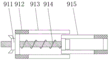
fig. 5 is a schematic structural view of the fixing clip of the present invention.
In the figure: 100. a photovoltaic panel; 1. a mounting frame; 2. a rotating shaft; 3. a lifting cylinder; 4. fixing a pin shaft; 5. a fixing leg; 6. a turntable; 7. mounting a plate; 8. a support pillar; 9. a transverse support; 91. fixing the clamp; 911. a fastening cap; 912. a clip; 913. an outer housing; 914. a threaded post; 915. an inlay; 10. a longitudinal support; 101. a movable trough body; 102. mounting grooves; 103. a rotating shaft sleeve; 104. a fixed groove body.
Detailed Description
The technical solutions in the embodiments of the present invention will be described clearly and completely with reference to the accompanying drawings in the embodiments of the present invention, and it is obvious that the described embodiments are only some embodiments of the present invention, not all embodiments. Based on the embodiments of the present invention, all other embodiments obtained by a person of ordinary skill in the art without creative efforts belong to the protection scope of the present invention.
Referring to fig. 1-5, the utility model relates to a photovoltaic aluminum integrated structure with fixing feet, which comprises a mounting frame 1 for mounting a photovoltaic plate 100 and a mounting plate 7, wherein the mounting plate 7 is arranged below the mounting frame 1, supporting columns 8 are arranged at the corners of the bottom of the mounting plate 7, the fixing feet 5 are arranged at the bottoms of the supporting columns 8, a lifting cylinder 3 is rotatably arranged at one end of the top of the mounting plate 7, rotary tables 6 are arranged at the two sides of the middle part of the top of the mounting plate 7, and the rotary tables 6 at the two sides are respectively sleeved at the two ends of a;
Specifically, a plurality of fixed pin shafts 4 are arranged on the fixed feet 5, and the fixed feet 5 are fixedly arranged on the ground through the fixed pin shafts 4; an output shaft of the lifting cylinder 3 is rotatably connected with the bottom of one end of the longitudinal support 10 far away from the fixed groove body 104, and the rotary tables 6 on the two sides are rotatably connected with the rotary shaft sleeve 103 through the rotary shaft 2; the fixing clamp 91 comprises an outer shell 913 and an inner embedded body 915, wherein the inner embedded body 915 is embedded in one end of the outer shell 913, a clamp 912 is vertically arranged at one end of each of the outer shell 913 and the inner embedded body 915, a fastening cap 911 is arranged at one side, away from the inner embedded body 915, of the outer shell 913, a threaded column 914 is arranged inside the inner embedded body 915, the threaded column 914 penetrates through one end of the outer shell 913, and the fastening cap 911 is in threaded sleeve connection with one end of the threaded column 914; the inside cockscomb structure that is of clip 912, the inside slipmat that is equipped with the rubber material of clip 912, cup jointed coil spring on the screw post 914.
Referring to fig. 1-5, the working process of the integrated photovoltaic aluminum structure with fixing pins of the present embodiment is as follows:
the method comprises the following steps: moving the photovoltaic aluminum integrated structure with the fixing feet to an installation place, and fixedly installing the fixing feet 5 on the ground through a plurality of fixing pin shafts 4 so as to fix the structure on the installation place;
step two: loosening fastening bolts at the bottom of the connection part of the trough body 101 and the longitudinal support 10, pulling the movable trough body 101 out of the longitudinal support 10, extending the photovoltaic panel 100 from one end of the longitudinal support 10 until the bottom end of the photovoltaic panel 100 is positioned in the fixed trough body 104 and two sides of the photovoltaic panel are positioned in the fixed clamp 91, and installing the movable trough body 101 on the top end of the photovoltaic panel 100 and fixing the movable trough body on the longitudinal support 10 through the fastening bolts;
step three: screwing the fastening cap 911, wherein the fastening cap 911 is screwed with the threaded column 914 to enable the threaded column 914 to approach the fastening cap 911, so that the distance of the inner inlay 915 extending into the outer shell 913 is increased, the inner inlay 915 and the clamp 912 on the outer shell 913 approach to clamp the photovoltaic panel 100;
step four: the lifting cylinder 3 is started, the rotary table 6, the rotary shaft 2 and the rotary shaft sleeve 103 are connected in a rotating mode, the lifting cylinder 3 extends upwards to push the longitudinal support 10 to move upwards, the mounting frame 1 makes circular motion around the rotary table 6, and the photovoltaic panel 100 is pushed to face the sunlight.
The foregoing is merely exemplary and illustrative of the structure of the invention, and various modifications, additions and substitutions as described in the detailed description may be made by those skilled in the art without departing from the structure or exceeding the scope of the invention as defined in the claims.
Claims (5)
1. The photovoltaic aluminum integrated structure with the fixing pins is characterized by comprising a mounting frame (1) and a mounting plate (7) for mounting a photovoltaic plate (100), wherein the mounting plate (7) is arranged below the mounting frame (1), supporting columns (8) are mounted at corners of the bottom of the mounting plate (7), the fixing pins (5) are mounted at the bottom of the supporting columns (8), a lifting cylinder (3) is mounted at one end of the top of the mounting plate (7), rotary tables (6) are mounted on two sides of the middle of the top of the mounting plate (7), and the rotary tables (6) on two sides are respectively sleeved on two ends of a rotating shaft (2);
mounting bracket (1) is including vertical support (10), horizontal support (9), vertical support (10) one end activity embedding is installed and is moved cell body (101), move cell body (101) and install fastening bolt with vertical support (10) junction bottom, vertical support (10) are kept away from and are moved cell body (101) one end and install and decide cell body (104), mounting groove (102) have been seted up to vertical support (10) intermediate position, mounting groove (102) bottom is connected with pivot cover (103), vertical support (10) are installed horizontal support (9) through mounting groove (102) embedding, mounting fixture (91) are all installed at horizontal support (9) both ends.
2. The photovoltaic aluminum integrated structure with the fixing legs as claimed in claim 1, wherein the fixing legs (5) are provided with a plurality of fixing pins (4), and the fixing legs (5) are fixedly arranged on the ground through the plurality of fixing pins (4).
3. The photovoltaic aluminum integrated structure with the fixing legs as claimed in claim 1, wherein an output shaft of the lifting cylinder (3) is rotatably connected with the bottom of one end of the longitudinal support (10) far away from the fixing groove body (104), and the rotary tables (6) on two sides are rotatably connected with the rotary shaft sleeve (103) through the rotary shaft (2).
4. The photovoltaic aluminum integrated structure with the fixing foot as claimed in claim 1, wherein the fixing clamp (91) comprises an outer shell (913) and an inner embedded body (915), the inner embedded body (915) is embedded and installed at one end of the outer shell (913), a clamp (912) is vertically installed at one end of each of the outer shell (913) and the inner embedded body (915), a fastening cap (911) is arranged on one side, away from the inner embedded body (915), of the outer shell (913), a threaded column (914) is installed inside the inner embedded body (915), the threaded column (914) penetrates through one end of the outer shell (913), and the fastening cap (911) is in threaded sleeve connection with one end of the threaded column (914).
5. The photovoltaic aluminum integrated structure with the fixing foot as claimed in claim 4, wherein the inside of the clip (912) is serrated, the inside of the clip (912) is provided with a rubber anti-skid pad, and the threaded column (914) is sleeved with a coil spring.
Priority Applications (1)
| Application Number | Priority Date | Filing Date | Title |
|---|---|---|---|
| CN201922115803.2U CN210986006U (en) | 2019-12-02 | 2019-12-02 | Photovoltaic aluminum integrated structure with fixing feet |
Applications Claiming Priority (1)
| Application Number | Priority Date | Filing Date | Title |
|---|---|---|---|
| CN201922115803.2U CN210986006U (en) | 2019-12-02 | 2019-12-02 | Photovoltaic aluminum integrated structure with fixing feet |
Publications (1)
| Publication Number | Publication Date |
|---|---|
| CN210986006U true CN210986006U (en) | 2020-07-10 |
Family
ID=71417991
Family Applications (1)
| Application Number | Title | Priority Date | Filing Date |
|---|---|---|---|
| CN201922115803.2U Active CN210986006U (en) | 2019-12-02 | 2019-12-02 | Photovoltaic aluminum integrated structure with fixing feet |
Country Status (1)
| Country | Link |
|---|---|
| CN (1) | CN210986006U (en) |
-
2019
- 2019-12-02 CN CN201922115803.2U patent/CN210986006U/en active Active
Similar Documents
| Publication | Publication Date | Title |
|---|---|---|
| CN106439426B (en) | A kind of photovoltaic board mount of tilt adjustable | |
| CN209725908U (en) | A kind of LED light of adjustable environmental protection and energy saving | |
| CN109973907A (en) | A kind of environment-friendly and energy-efficient LED light being easily installed disassembly | |
| CN113489427A (en) | Wind-solar-storage integrated power generation equipment convenient to install and use | |
| CN213118917U (en) | Energy-concerving and environment-protective light for building | |
| CN210986006U (en) | Photovoltaic aluminum integrated structure with fixing feet | |
| CN210113724U (en) | Solar panel's fixed adjustment base | |
| CN207947746U (en) | A kind of photovoltaic solar bracket mounting device | |
| CN107612475B (en) | It is a kind of too can solar panel regulating device | |
| CN216740926U (en) | Anti-overturning high-voltage line power transmission steel structure iron tower | |
| CN213778216U (en) | Solar energy collection device | |
| CN215927658U (en) | Domestic aerogenerator fixed mounting frame | |
| CN211321387U (en) | Outdoor large-scale wild animal's shooting device | |
| CN207801832U (en) | A kind of unitary adjustable section photovoltaic bracket | |
| CN202972894U (en) | Light-emitting diode (LED) street lamp with solar tracking device | |
| CN217824868U (en) | Foldable integrated photovoltaic power generation equipment | |
| CN221806810U (en) | Portable stowable photovoltaic mounting plate structure | |
| CN218103021U (en) | Combined mounting rack for solar power generation panel | |
| CN221644477U (en) | Solar street lamp lifting device | |
| CN217388617U (en) | Photovoltaic power generation assembly with function of adjusting illumination receiving area | |
| CN218648753U (en) | Support structure | |
| CN209787099U (en) | Solar photovoltaic support that fastness is high | |
| CN210899022U (en) | Simple to operate's photovoltaic support | |
| CN220693065U (en) | Photovoltaic power generation illumination tracking and positioning structure | |
| CN211296641U (en) | Solar panel bracket |
Legal Events
| Date | Code | Title | Description |
|---|---|---|---|
| GR01 | Patent grant | ||
| GR01 | Patent grant |