CN210974194U - Comprehensive utilization system for phosphogypsum backwater - Google Patents
Comprehensive utilization system for phosphogypsum backwater Download PDFInfo
- Publication number
- CN210974194U CN210974194U CN201921497866.2U CN201921497866U CN210974194U CN 210974194 U CN210974194 U CN 210974194U CN 201921497866 U CN201921497866 U CN 201921497866U CN 210974194 U CN210974194 U CN 210974194U
- Authority
- CN
- China
- Prior art keywords
- tank
- pipeline
- storage tank
- filtrate
- outlet
- Prior art date
- Legal status (The legal status is an assumption and is not a legal conclusion. Google has not performed a legal analysis and makes no representation as to the accuracy of the status listed.)
- Active
Links
Images


Abstract
The utility model discloses a comprehensive utilization system of ardealite return water belongs to phosphoric acid technical field. The system comprises a phosphogypsum backwater storage tank, a neutralization reaction storage tank, a multi-stage neutralization reaction tank, a lime water storage tank, a settling tank, a filter press, a repulping tank and a filtrate storage tank; a cooling water inlet and a cooling water outlet of the phosphoric acid atmosphere condenser are respectively connected with a phosphogypsum backwater storage tank and a neutralization reaction storage tank through pipelines; the inlet of the multistage neutralization reaction tank is connected with the neutralization reaction storage tank and the lime water storage tank; the inlet of the settling tank is connected with the outlet of the multistage neutralization reaction tank through a pipeline, the slurry outlet of the settling tank is connected with the repulping tank through a pipeline, and the clear liquid outlet of the settling tank is connected with the inlet of the filter press and the ball mill through pipelines; a filter residue outlet of the filter press is connected with the repulping tank through a pipeline, and a filtrate outlet of the filter press is connected with a filtrate storage tank through a pipeline; the filtrate storage tank is connected with a washing water inlet of the vacuum disc filter through a pipeline. The return water is used for cooling water, filtering washing water and ore grinding water.
Description
Technical Field
The utility model belongs to the technical field of phosphoric acid production, in particular to comprehensive utilization system of ardealite return water.
Background
Phosphogypsum is an industrial byproduct gypsum generated in the production of high-concentration phosphorus compound fertilizer, and the main component of the phosphogypsum is calcium sulfate dihydrate (CaSO)4·2H2O), 1 ton of phosphoric acid (100% P) is prepared2O5Measured) to produce 4.8-5.0 tons of phosphogypsum, and the pressure of solid waste is very large, so the phosphogypsum needs to be treated in time. At present, phosphogypsum stacking of domestic manufacturers generally adopts two methods of wet discharging stacking and dry discharging and dry stacking.
Wet dumping: the filtering station of the phosphoric acid device adopts wet-method deslagging, phosphogypsum is firstly mixed with water to prepare phosphogypsum slag slurry with 70-80% of water, then the phosphogypsum slag slurry is pumped to a phosphogypsum tailing pond by adopting a one-stage or multi-stage pump according to the distance of conveying, and clear water after natural sedimentation is pumped to the phosphoric acid device by using water for reuse. The method is generally adopted by domestic large-scale wet-process phosphoric acid devices. The method has the advantages of high recovery rate of wastewater and phosphoric acid, environmental protection, energy conservation, convenient operation, low operating cost and the like.
Dry draining and piling: the dry discharging and dry piling process is the ardealite piling mode which is applied to the wet phosphoric acid production at first. The filtering station of the phosphoric acid device adopts dry-method deslagging, the phosphogypsum with the water content of less than 20 percent is conveyed to a phosphogypsum warehouse by a belt conveyor, and then an automobile or a belt conveyor is transported to a slag yard outside a plant area.
In the prior art, a wet-process slag discharging process is adopted, gypsum is built for stockpiling, seepage water is collected in a water return pool and recycled by a pumping phosphoric acid system (a ball mill), and thus the water balance of the whole phosphoric acid system is formed.
For example, the Chinese patent with the application number of CN201720709697.9 discloses a phosphogypsum backwater recycling system, which comprises a storage yard, an online neutralization device, a ball mill and an acidification tank which are arranged in sequence; the storage yard is connected with the online neutralizing device through a pipeline, the online neutralizing device is connected with the ball mill through a pipeline, and the ball mill is connected with the acidification tank through a pipeline. For example, chinese patent application No. CN201720709697.9 discloses a ball mill using phosphorus tailings backwater, which comprises a ball mill body and a feeding device, wherein the feeding device is arranged on the ball mill body; the feeding device comprises a solid feeding pipe, a liquid feeding pipe and an on-line neutralizing cylinder, wherein the solid feeding pipe is obliquely arranged, and the lower end of the solid feeding pipe is communicated with a feeding hole of the ball mill body; the middle pipe wall of the solid feeding pipe is upwards provided with a water diversion opening, the liquid feeding pipe is vertically arranged, the lower end of the liquid feeding pipe is communicated with the water diversion opening, and the upper end of the liquid feeding pipe is communicated with the online neutralization cylinder.
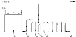
Referring to fig. 1, in order to provide an existing phosphogypsum recycling system, a phosphogypsum storage yard collects phosphogypsum and washing water output by a vacuum disc filter, the phosphogypsum and the washing water are dehumidified to obtain return water, the return water is sent to a phosphogypsum return water storage tank to be stored, and the return water is sent to a ball mill for utilization by the phosphogypsum return water storage tank.
The applicant, when using the aforementioned system, has found at least the following 3 problems:
1. the ball mill cannot utilize all backwater in time (fluctuation of capacity), and when the ball mill operates at low capacity, excessive backwater needs to be discharged;
2. the pH value of the return water is high, the corrosion to equipment (pipelines and pumps) is strong, and the service life of the equipment is short;
3. in the production of phosphoric acid, cooling water (an atmospheric condenser), washing water (a vacuum disc filter) and the like are used, and the water consumption is large.
SUMMERY OF THE UTILITY MODEL
In order to solve the problem, the embodiment of the utility model provides a comprehensive utilization system of ardealite return water is used for the cooling water of concentration process, the washing water and the water of grinding among the filtering process with the return water treatment. The technical scheme is as follows:
the embodiment of the utility model provides a comprehensive utilization system of ardealite return water, which comprises an ardealite return water storage tank, a neutralization reaction storage tank 1, a multistage neutralization reaction tank 5, a lime water storage tank, a settling tank 7, a filter press 12, a repulping tank 13 and a filtrate storage tank 17; a cooling water inlet and a cooling water outlet of the phosphoric acid atmospheric condenser are respectively connected with a phosphogypsum backwater storage tank and a neutralization reaction storage tank 1 through pipelines; the inlet of the multistage neutralization reaction tank 5 is connected with the neutralization reaction storage tank 1 and the lime water storage tank; the inlet of the settling tank 7 is connected with the outlet of the multistage neutralization reaction tank 5 through a pipeline, the slurry outlet of the settling tank is connected with the repulping tank 13 through a pipeline, and the clear liquid outlet of the settling tank is connected with the inlet of the filter press 12 and the ball mill through a pipeline; a filter residue outlet of the filter press 12 is connected with the repulping tank 13 through a pipeline, and a filtrate outlet of the filter press is connected with a filtrate storage tank 17 through a pipeline; the filtrate storage tank 17 is connected with a washing water inlet of the vacuum disc filter through a pipeline.
Specifically, the embodiment of the utility model provides an in the neutralization reaction storage tank 1 with multistage neutralization reaction tank 5 between the pipeline be equipped with for the return water pump 2, multistage neutralization reaction tank 5 is established ties by 4 reaction tanks 3 and forms, the lime wash storage tank is connected with first order reaction tank 3 through the pipeline, last order reaction tank 3 is through the pipeline of taking reaction slurry pump 6 and the access connection at settling tank 7 top; the reaction tank 3 is internally provided with a stirrer 4 which is provided with a heating jacket and/or a heating coil.
Specifically, the slurry outlet of the settling tank 7 in the embodiment of the present invention is arranged at the bottom thereof, the clarified liquid outlet thereof is arranged on the side wall thereof, the top thereof is provided with a flocculant adding port, and the clarified liquid outlet thereof is connected with the inlet of the filter press 12 and the ball mill through a pipeline with a valve group; a clear liquid pump 10 is arranged on a pipeline between the settling tank 7 and the ball mill, and a filter pressing feed pump 11 is arranged on a pipeline between the settling tank 7 and the filter press 12.
Further, the comprehensive utilization system in the embodiment of the utility model further comprises a slurry and slag collecting tank 8, wherein the slurry and slag collecting tank 8 is arranged between the settling tank 7 and the repulping tank 13; the slurry and slag collecting tank 8 is positioned below the settling tank 7, a stirrer 4 is arranged in the slurry and slag collecting tank, a feed inlet of the stirrer is connected with a slurry outlet of the settling tank 7 through a pipeline, and a discharge outlet of the stirrer is connected with a re-slurry tank 13 through a pipeline with a slurry and slag pump 9.
Further, the comprehensive utilization system in the embodiment of the present invention further includes a filtrate collecting tank 15, wherein the filtrate collecting tank 15 is disposed between a filtrate outlet of the filter press 12 and a filtrate storage tank 17; the filter press 12 is higher than the reslurry tank 13 and the filtrate collection tank 15; the repulping tank 13 is internally provided with a stirrer 4 which is connected with the slurry tank through a pipeline with a repulping pump 14; the filtrate collection tank 15 is connected to a filtrate storage tank 17 via a line with a filtrate pump 16.
Specifically, the filtrate storage tank 17 in the embodiment of the present invention is connected to the three washing water inlets of the vacuum disc filter through a pipeline with the filtrate delivery pump 18.
The embodiment of the utility model provides a beneficial effect that technical scheme brought is: the embodiment of the utility model provides a comprehensive utilization system of phosphogypsum backwater, the backwater is sent into a phosphoric acid atmosphere condenser to be used as cooling water; the heated backwater reacts with lime water, the pH value is reduced, and P is settled; then sending the slurry into a settling tank to react with a flocculating agent, sending the lower layer slurry into a slurry tank, and respectively sending the upper layer clear liquid into a filter press or a ball mill (main) according to the actual water use condition; sending filtrate obtained by filter pressing of the filter press to a vacuum disc type filter to be used as washing water (the last washing area), and sending filter residue to a repulping tank; and the slurry (with high phosphorus content) in the slurry tank is adjusted by the slurry tank and then is sent to the slurry tank. In conclusion, the system comprehensively utilizes the return water, saves water, reduces the discharge of acid wastewater and prolongs the service life of the recovery and conveying equipment.
Drawings
Fig. 1 is a schematic block diagram of an existing phosphogypsum recycling system;
FIG. 2 is a schematic block diagram of a comprehensive utilization system of phosphogypsum backwater provided by an embodiment of the utility model;
fig. 3 is a schematic view of a partial structure of the comprehensive utilization system of the phosphogypsum backwater provided by the embodiment;
fig. 4 is another part of the comprehensive utilization system of the phosphogypsum backwater provided by the embodiment of the utility model.
In the figure: 1 neutralization reaction storage tank, 2 water feeding and returning pumps, 3 reaction tanks, 4 stirrers, 5 multi-stage neutralization reaction tanks, 6 reaction slurry pumps, 7 settling tanks, 8 slurry and slag collecting tanks, 9 slurry pumps, 10 clarified liquid pumps, 11 filter pressing and feeding pumps, 12 filter presses, 13 repulping tanks, 14 repulping pumps, 15 filtrate collecting tanks, 16 filtrate pumps, 17 filtrate storage tanks and 18 filtrate delivery pumps.
Detailed Description
In order to make the objects, technical solutions and advantages of the present invention clearer, the present invention will be described in further detail with reference to the accompanying drawings.
Referring to fig. 2-4, the embodiment of the utility model provides a comprehensive utilization system of ardealite return water, this system includes ardealite return water storage tank, neutralization reaction storage tank 1, multistage neutralization reaction tank 5, lime wash storage tank, subsider 7, pressure filter 12, repulping groove 13 and filtrating storage tank 17 etc.. The phosphogypsum backwater storage tank is used for storing phosphogypsum backwater (P) collected from a phosphogypsum storage yard2O5About 0.8% and a pH value of about 3); the neutralization reaction storage tank 1 is used for reacting the backwater with the lime water and controlling the pH value of the reaction tank to be about 7 (the density is 1.1 g/cm)3Left and right); the settling tank 7 is used for settling the slurry after the neutralization reaction, and adding a flocculating agent (the flocculating agent for phosphoric acid from Wuhanjinpo environmental protection or Wuhanxinlun environmental protection, the dosage is 0.05-2%, and the time is 2-8 hours); the filter press 12 is used for carrying out filter pressing on the clear liquid in the settling tank 7, only a common plate-and-frame filter press is adopted, and the filtrate is not turbid by visual inspection; the repulping tank 13 is used for collecting the bottom layer slurry of the settling tank 7 and the filter residue of the filter press 12, and is adjusted to facilitate the pump delivery (the filtrate or the supernatant of the settling tank 7 can be added for adjustment, the two substances are basically directly mixed in the patent, and the density is preferably adjusted to 1.72-1.78g/cm3As dense as pulp); the filtrate storage tank 17 is for storing filtrate (P)2O5About 0.2% and pH valueAbout 6). The cooling water inlet and the cooling water outlet (retaining a water cooling tower, particularly being connected with a circulating groove at the bottom in the water cooling tower) of the phosphoric acid atmospheric condenser (the structure in the phosphoric acid concentration device, the existing atmospheric condenser which can adopt acid water as cooling water) are respectively connected with a phosphogypsum backwater storage tank and a neutralization reaction storage tank 1 through pipelines, so as to cool the phosphoric acid concentration device and heat the backwater to be beneficial to neutralization reaction. The inlet of the multistage neutralization reaction tank 5 is connected with the neutralization reaction tank 1 and the lime water tank to perform neutralization reaction. The inlet of the settling tank 7 is connected with the outlet of the multistage neutralization reaction tank 5 through a pipeline, the slurry outlet of the settling tank is connected with the repulping tank 13 through a pipeline, and the clear liquid outlet of the settling tank is connected with the inlet of the filter press 12 and the ball mill through a pipeline. The residue outlet of the filter press 12 (which is collected by a residue hopper and discharged by process water or recovery flushing) is connected to the reslurry tank 13 via a pipeline, and the filtrate outlet is connected to the filtrate storage tank 17 via a pipeline. The filtrate storage tank 17 is connected with a washing water inlet of the vacuum disc filter through a pipeline. And structures such as a pump, a valve and/or a flowmeter are arranged on a pipeline between the structures according to requirements.
Specifically, referring to fig. 3, the embodiment of the present invention provides a water supply and return pump 2 on the pipeline between the neutralization reaction tank 1 and the multi-stage neutralization reaction tank 5, the multi-stage neutralization reaction tank 5 is formed by connecting 4 reaction tanks 3 in series, the inlet and outlet of each reaction tank 3 are respectively located on the upper and lower parts, and the outlet of the upper stage and the inlet of the lower stage are both located on the upper part or are both located on the lower part. The lime water storage tank is connected with the first-stage reaction tank 3 through a pipeline, and the last-stage reaction tank 3 is provided with a reaction slurry pump 6 (the flow is 200 m)3About/h, the flow of the subsequent pump is matched with the pump) is connected with the inlet at the top of the settling tank 7. Be equipped with agitator 4 in the reaction tank 3, be equipped with heating jacket (locate outside reaction tank 3, be connected with the steam pipe network) and/or heating coil (locate in reaction tank 3, be connected with the steam pipe network) on it and be used for realizing the heating, its size specifically is phi 4500mm h4500mm (return water volume 80 m year/h is left and right sides), and the specification of agitator 4 in it is phi 1800mm, and the rotational speed is about 50 r/min.
Specifically, referring to fig. 3 and 4, the slurry outlet of the settling tank 7 in the embodiment of the present invention is disposed at the bottom (conical shape), the clarified liquid outlet thereof is disposed on the side wall thereof, the top thereof is provided with a flocculant adding port for adding a flocculant, and the clarified liquid outlet thereof is connected with the inlet of the filter press 12 and the ball mill through a pipeline with a valve group (which can be controlled to send the supernatant liquid into the ball mill completely, into the ball mill partially or not) by controlling the valve group. A clear liquid pump 10 is arranged on a pipeline between the settling tank 7 and the ball mill, and a filter pressing feeding pump 11 is arranged on a pipeline between the settling tank 7 and the filter press 12.
Further, referring to fig. 4, the comprehensive utilization system in the embodiment of the present invention further includes a slurry-slag collecting tank 8 (geosyncline), and the slurry-slag collecting tank 8 is disposed between the settling tank 7 and the reslurry tank 13; the slurry-residue collecting tank 8 is positioned below the settling tank 7, a stirrer 4 is arranged in the slurry-residue collecting tank, a feed inlet of the stirrer is connected with a slurry outlet of the settling tank 7 through a pipeline, and a discharge outlet of the stirrer is connected with a secondary slurry tank 13 (ground tank) through a pipeline with a slurry-residue pump 9.
Further, the utility model provides an in the embodiment of the comprehensive utilization system still include filtrating collecting vat 15 (less than filtrating storage tank 17, be close to pressure filter 12 and set up and be used for collecting the filtrating), filtrating collecting vat 15 is located between filtrating export and the filtrating storage tank 17 of pressure filter 12. The filter press 12 is higher than the reslurry tank 13 and the filtrate collection tank 15. The repulping tank 13 is internally provided with a stirrer 4 which is connected with the slurry tank through a pipeline with a repulping pump 14. The filtrate collection tank 15 is connected to a filtrate storage tank 17 via a line with a filtrate pump 16.
Specifically, the filtrate storage tank 17 in the embodiment of the present invention is connected to the three washing water inlets of the vacuum disc filter (the washing water inlet of the last washing zone (three washing zones), the washing water inlet of the previous washing zone and the washing water outlet of the adjacent and subsequent washing zone (e.g., the washing water inlet of the second washing zone is connected to the washing water outlet of the third washing zone)) through a pipeline with the filtrate delivery pump 18.
The above description is only for the preferred embodiment of the present invention, and is not intended to limit the present invention, and any modifications, equivalent replacements, improvements, etc. made within the spirit and principle of the present invention should be included within the protection scope of the present invention.
Claims (6)
1. The comprehensive phosphogypsum backwater utilization system comprises a phosphogypsum backwater storage tank; the system is characterized by also comprising a neutralization reaction storage tank (1), a multi-stage neutralization reaction tank (5), a lime water storage tank, a settling tank (7), a filter press (12), a repulping tank (13) and a filtrate storage tank (17); a cooling water inlet and a cooling water outlet of the phosphoric acid atmosphere condenser are respectively connected with a phosphogypsum backwater storage tank and a neutralization reaction storage tank (1) through pipelines; the inlet of the multistage neutralization reaction tank (5) is connected with the neutralization reaction storage tank (1) and the lime water storage tank; the inlet of the settling tank (7) is connected with the outlet of the multistage neutralization reaction tank (5) through a pipeline, the slurry outlet of the settling tank is connected with the repulping tank (13) through a pipeline, and the clear liquid outlet of the settling tank is connected with the inlet of the filter press (12) and the ball mill through a pipeline; a filter residue outlet of the filter press (12) is connected with the repulping tank (13) through a pipeline, and a filtrate outlet of the filter press is connected with a filtrate storage tank (17) through a pipeline; the filtrate storage tank (17) is connected with a washing water inlet of the vacuum disc filter through a pipeline.
2. The comprehensive utilization system of phosphogypsum backwater according to claim 1, characterized in that a water supply and return pump (2) is arranged on a pipeline between the neutralization reaction storage tank (1) and the multistage neutralization reaction tanks (5), the multistage neutralization reaction tanks (5) are formed by connecting 4 reaction tanks (3) in series, the lime water storage tank is connected with the first stage reaction tank (3) through a pipeline, and the last stage reaction tank (3) is connected with an inlet at the top of the settling tank (7) through a pipeline with a reaction slurry pump (6); a stirrer (4) is arranged in the reaction tank (3), and a heating jacket and/or a heating coil are/is arranged on the stirrer.
3. The comprehensive utilization system of phosphogypsum backwater according to claim 2, characterized in that the slurry outlet of the settling tank (7) is arranged at the bottom thereof, the clear liquid outlet thereof is arranged on the side wall thereof, the top thereof is provided with a flocculant adding port, and the clear liquid outlet thereof is connected with the inlet of the filter press (12) and the ball mill through a pipeline with a valve group; a clear liquid pump (10) is arranged on a pipeline between the settling tank (7) and the ball mill, and a filter pressing feed pump (11) is arranged on a pipeline between the settling tank (7) and the filter press (12).
4. The comprehensive utilization system of phosphogypsum backwater according to claim 3, characterized in that the system further comprises a slurry-slag collecting tank (8), wherein the slurry-slag collecting tank (8) is arranged between the settling tank (7) and the repulping tank (13); the slurry residue collecting tank (8) is positioned below the settling tank (7), a stirrer (4) is arranged in the slurry residue collecting tank, a feed inlet of the slurry residue collecting tank is connected with a slurry outlet of the settling tank (7) through a pipeline, and a discharge outlet of the slurry residue collecting tank is connected with a re-slurry tank (13) through a pipeline with a slurry residue pump (9).
5. The comprehensive utilization system of phosphogypsum backwater according to claim 4, characterized in that the system further comprises a filtrate collecting tank (15), wherein the filtrate collecting tank (15) is arranged between a filtrate outlet of the filter press (12) and a filtrate storage tank (17); the filter press (12) is higher than the reslurry tank (13) and the filtrate collecting tank (15); a stirrer (4) is arranged in the repulping tank (13) and is connected with the slurry tank through a pipeline with a repulping pump (14); the filtrate collecting tank (15) is connected with a filtrate storage tank (17) through a pipeline with a filtrate pump (16).
6. The comprehensive utilization system of phosphogypsum backwater according to claim 5, characterized in that the filtrate storage tank (17) is connected with a triple washing water inlet of a vacuum disc filter through a pipeline with a filtrate delivery pump (18).
Priority Applications (1)
| Application Number | Priority Date | Filing Date | Title |
|---|---|---|---|
| CN201921497866.2U CN210974194U (en) | 2019-09-10 | 2019-09-10 | Comprehensive utilization system for phosphogypsum backwater |
Applications Claiming Priority (1)
| Application Number | Priority Date | Filing Date | Title |
|---|---|---|---|
| CN201921497866.2U CN210974194U (en) | 2019-09-10 | 2019-09-10 | Comprehensive utilization system for phosphogypsum backwater |
Publications (1)
| Publication Number | Publication Date |
|---|---|
| CN210974194U true CN210974194U (en) | 2020-07-10 |
Family
ID=71419814
Family Applications (1)
| Application Number | Title | Priority Date | Filing Date |
|---|---|---|---|
| CN201921497866.2U Active CN210974194U (en) | 2019-09-10 | 2019-09-10 | Comprehensive utilization system for phosphogypsum backwater |
Country Status (1)
| Country | Link |
|---|---|
| CN (1) | CN210974194U (en) |
Cited By (2)
| Publication number | Priority date | Publication date | Assignee | Title |
|---|---|---|---|---|
| CN113800956A (en) * | 2021-10-27 | 2021-12-17 | 湖北祥云(集团)化工股份有限公司 | Method and device for producing calcium magnesium phosphate fertilizer by removing magnesium clear liquid |
| CN115557719A (en) * | 2022-08-16 | 2023-01-03 | 湖北祥云(集团)化工股份有限公司 | Comprehensive treatment method of phosphogypsum |
-
2019
- 2019-09-10 CN CN201921497866.2U patent/CN210974194U/en active Active
Cited By (3)
| Publication number | Priority date | Publication date | Assignee | Title |
|---|---|---|---|---|
| CN113800956A (en) * | 2021-10-27 | 2021-12-17 | 湖北祥云(集团)化工股份有限公司 | Method and device for producing calcium magnesium phosphate fertilizer by removing magnesium clear liquid |
| CN115557719A (en) * | 2022-08-16 | 2023-01-03 | 湖北祥云(集团)化工股份有限公司 | Comprehensive treatment method of phosphogypsum |
| CN115557719B (en) * | 2022-08-16 | 2023-08-15 | 湖北祥云(集团)化工股份有限公司 | Comprehensive treatment method of phosphogypsum |
Similar Documents
| Publication | Publication Date | Title |
|---|---|---|
| CN105000585B (en) | In ardealite and purification process technique | |
| CN210974194U (en) | Comprehensive utilization system for phosphogypsum backwater | |
| CN109824186B (en) | Process for lifting mineral sand circulation high-speed sedimentation tank through negative pressure | |
| CN204779369U (en) | In ardealite and purification treatment system | |
| CN203513348U (en) | Sludge water treatment and reuse system for settling pond | |
| CN110963654A (en) | Engineering slurry treatment system and method | |
| CN110845118A (en) | Ecological dredging system and method | |
| CN205501073U (en) | Papermaking wastewater treatment system | |
| CN101423203A (en) | Water-saving and emission-reducing wet method phosphoric acid manufacture process | |
| CN110510589A (en) | A kind of Wet-process Phosphoric Acid Production method and production system | |
| CN202576190U (en) | Combined sludge deep dehydration device | |
| CN101798768A (en) | Waste paper regeneration environmental protection device and method | |
| CN211226877U (en) | Ecological dredging system | |
| CN112028342A (en) | Converter steel slag hot-stewing turbid circulating water treatment device and process | |
| CN115625181A (en) | Phosphogypsum harmless treatment system | |
| CN109231684B (en) | Treatment method and system for purifying phosphogypsum storage yard penetrating fluid | |
| CN115557719A (en) | Comprehensive treatment method of phosphogypsum | |
| CN210964210U (en) | Phosphoric acid carousel vacuum filter equipment of difficult scale deposit | |
| CN215209078U (en) | Automatic recycling system for sludge dewatering of sewage system | |
| CN205110340U (en) | Responsibility is arranged all to ardealite | |
| CN210973888U (en) | Wet process phosphoric acid production system | |
| CN214880466U (en) | Automatic control device for hardness of neutralized water | |
| CN216377506U (en) | Recycling device for phosphogypsum backwater | |
| Young | Water treatment plant sludge disposal practices in the United Kingdom | |
| CN204689863U (en) | A kind of sludge condensation division box and system |
Legal Events
| Date | Code | Title | Description |
|---|---|---|---|
| GR01 | Patent grant | ||
| GR01 | Patent grant |