CN210964804U - Automatic chemical fertilizer mixer of pay-off - Google Patents
Automatic chemical fertilizer mixer of pay-off Download PDFInfo
- Publication number
- CN210964804U CN210964804U CN201921844945.6U CN201921844945U CN210964804U CN 210964804 U CN210964804 U CN 210964804U CN 201921844945 U CN201921844945 U CN 201921844945U CN 210964804 U CN210964804 U CN 210964804U
- Authority
- CN
- China
- Prior art keywords
- equipment box
- fixed
- fan
- plate
- driving
- Prior art date
- Legal status (The legal status is an assumption and is not a legal conclusion. Google has not performed a legal analysis and makes no representation as to the accuracy of the status listed.)
- Expired - Fee Related
Links
Images


Abstract
The utility model discloses an automatic feeding chemical fertilizer stirrer, which comprises an equipment box, a driving motor, a driving shaft, a driven shaft, a first stirring plate, a second stirring plate, a bottom plate, a connecting plate and a servo motor, wherein the equipment box is arranged above the bottom plate, the bottom of the equipment box is symmetrically fixed with the connecting plate, one end of the connecting plate far away from the equipment box is fixedly connected with the bottom plate, the top of the equipment box is fixed with a supporting plate, one side of the supporting plate is fixed with the driving motor, the outer side of an output shaft of the driving motor is sleeved and fixed with a driving gear, the inside of the equipment box is provided with the driving shaft and the driven shaft, one end of the driving shaft is rotatably connected with the inner wall at the bottom of the equipment box through a bearing, the other end of the driving shaft passes through the end part of the output shaft of the equipment box and is fixedly connected with, the device can stir the fertilizer, and the principle of the device is simple and convenient to operate.
Description
Technical Field
The utility model relates to a mixer technical field specifically is a chemical fertilizer mixer of autoloading.
Background
A stirrer is a construction engineering machine and is mainly used for stirring building materials such as cement, sand and stone, various dry-mixed mortar and the like. The mixer is a machine which rotates in a cylinder or a groove and is used for stirring and mixing a plurality of raw materials to form a mixture or a proper consistency, and the mixer is divided into various types, namely a forced mixer, a single horizontal shaft mixer, a double horizontal shaft mixer and the like.
The existing stirrer is high in feeding port, chemical fertilizers needing to be stirred are conveyed to the feeding port by manpower and then poured into an equipment box, the operation is labor-consuming, and therefore the chemical fertilizer stirrer capable of automatically feeding materials is provided.
Disclosure of Invention
An object of the utility model is to provide an autoloading's chemical fertilizer mixer to solve the problem that proposes among the above-mentioned background art.
In order to achieve the above object, the utility model provides a following technical scheme: an automatic chemical fertilizer mixer of pay-off, includes equipment box, driving motor, driving shaft, driven shaft, first stirring board, second stirring board, bottom plate, connecting plate and servo motor, the top of bottom plate is equipped with the equipment box, the bottom symmetry of equipment box is fixed with the connecting plate, the one end and the bottom plate fixed connection that the equipment box was kept away from to the connecting plate, the top of equipment box is fixed with the backup pad, one side of backup pad is fixed with driving motor, driving motor's the output shaft outside cup joints and is fixed with the driving gear, the inside of equipment box is equipped with driving shaft and driven shaft, the one end of driving shaft rotates through the bearing and is connected with the bottom inner wall of equipment box, the other end of driving shaft passes the equipment box and output shaft end fixed connection with driving motor, the one end of driven shaft rotates through the bottom inner wall of bearing and equipment box and is, the other end of the driven shaft penetrates through the top of the equipment box and is fixedly connected with the driven gear, the driven gear is meshed with the driving gear, a first stirring plate is fixedly sleeved on the outer surface of the lower section of the driving shaft in an equidistance manner, a second stirring plate is fixedly sleeved on the outer surface of the lower section of the driven shaft in an equidistance manner, the first stirring plate and the second stirring plate are mutually staggered, a feeding hole is formed in one side, close to the driving motor, of the equipment box, a discharging hole is formed in the bottom center of the equipment box, a fan-shaped fixing plate and a fan-shaped baffle are arranged in the discharging hole, the outer side of the fan-shaped fixing plate is fixedly connected with the side wall of the discharging hole, an arc-shaped through hole is formed in the upper surface of the fan-shaped fixing plate, the lower surface mounting of sector baffle has the handle, the one end that sector baffle was kept away from to the handle passes the arc through-hole and exposes in the air, one side symmetry that the equipment box is close to driving motor is fixed with the support arm, and is equipped with the premix bucket between two support arms, the spout has been seted up to one side of support arm, the drain hole of premix bucket is located between two support arms, and the drain hole contacts with the equipment box, the both sides that correspond of premix bucket all are fixed with the slider, slider sliding connection is in the spout, one side that driving motor was kept away from to the backup pad is equipped with servo motor, servo motor and the top fixed connection of two support arms, servo motor's output shaft fixed mounting has the kinking wheel, the surface winding of kinking wheel has the stay cord, and the one end and the premix.
Preferably, a shock pad is fixed to one side of the support plate.
Preferably, the sliding groove is internally coated with lubricating oil.
Preferably, a limiting block is fixed at the top end of the sliding chute.
Compared with the prior art, the beneficial effects of the utility model are that: pour into the chemical fertilizer that needs the stirring in the premix hopper in proportion, servo motor drives the premix hopper and rises, fertilizer can automatic entering into the equipment box when the discharge opening reachs the feed inlet in, driving motor passes through the driving gear and driven gear drives driving shaft and driven shaft rotation this moment, driving shaft and driven shaft rotation opposite direction, at this moment the first stirring board on the driving shaft and the second stirring board on the driven shaft stir the chemical fertilizer, alright take out with the chemical fertilizer that stirs when the anticlockwise rotation handle, the device principle simple operation is convenient.
Drawings
FIG. 1 is a schematic view of the overall structure of the present invention;
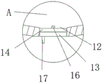
FIG. 2 is a schematic view of the A region structure of the present invention;
FIG. 3 is a schematic view of the structure of the support arm of the present invention;
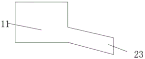
FIG. 4 is a schematic structural view of the premixing hopper of the present invention;
FIG. 5 is a schematic view of the fan-shaped fixing plate of the present invention;
fig. 6 is a schematic view of the structure of the fan-shaped baffle of the present invention.
In the figure: 1-equipment box; 2-a support plate; 3-driving a motor; 4-a drive gear; 5-driving shaft; 6-driven shaft; 7-a driven gear; 8-a first stirring plate; 9-a second stirring plate; 10-a feed inlet; 11-a premix hopper; 12-a discharge hole; 13-a sector fixing plate; 14-a sector baffle; 15-arc through holes; 16-a support bar; 17-a handle; 18-a shock pad; 19-a base plate; 20-a connecting plate; 21-a support arm; 22-a chute; 23-a discharge port; 24-a slide block; 25-a servo motor; 26-a wire winding wheel; 27-a pull rope; 28-a limiting block.
Detailed Description
The technical solutions in the embodiments of the present invention will be described clearly and completely with reference to the accompanying drawings in the embodiments of the present invention, and it is obvious that the described embodiments are only some embodiments of the present invention, not all embodiments. Based on the embodiments in the present invention, all other embodiments obtained by a person skilled in the art without creative work belong to the protection scope of the present invention.
Referring to fig. 1-6, the present invention provides a technical solution: the utility model provides an automatic chemical fertilizer mixer of pay-off, includes equipment box 1, driving motor 3, driving shaft 5, driven shaft 6, first stirring board 8, second stirring board 9, bottom plate 19, connecting plate 20 and servo motor 25, the top of bottom plate 19 is equipped with equipment box 1, the bottom symmetry of equipment box 1 is fixed with connecting plate 20, the one end and the bottom plate 19 fixed connection that equipment box 1 was kept away from to connecting plate 20, the top of equipment box 1 is fixed with backup pad 2, one side of backup pad 2 is fixed with driving motor 3, driving gear 4 is cup jointed and is fixed with in the output shaft outside of driving motor 3, the inside of equipment box 1 is equipped with driving shaft 5 and driven shaft 6, the one end of driving shaft 5 is passed through the bearing and is connected with the bottom inner wall rotation of equipment box 1, the other end of driving shaft 5 passes equipment box 1 with driving motor 3's output shaft tip fixed connection, one end of the driven shaft 6 is rotatably connected with the inner wall of the bottom of the equipment box 1 through a bearing, the other end of the driven shaft 6 penetrates through the top of the equipment box 1 and is fixedly connected with a driven gear 7, the driven gear 7 is meshed with a driving gear 4, a first stirring plate 8 is fixedly sleeved on the outer surface of the lower section of the driving shaft 5 in an equidistance manner, a second stirring plate 9 is fixedly sleeved on the outer surface of the lower section of the driven shaft 6 in an equidistance manner, the first stirring plate 8 and the second stirring plate 9 are mutually staggered, a feeding hole 10 is formed in one side, close to the driving motor 3, of the equipment box 1, a discharging hole 12 is formed in the center of the bottom of the equipment box 1, a fan-shaped fixed plate 13 and a fan-shaped baffle plate 14 are arranged in the discharging hole 12, the outer side of the fan-, a supporting rod 16 is fixed at the center of the upper surface of the fan-shaped fixing plate 13, one end of the supporting rod 16, far away from the fan-shaped fixing plate 13, penetrates through the fan-shaped baffle 14 and is rotationally connected with the fan-shaped baffle 14, a handle 17 is installed on the lower surface of the fan-shaped baffle 14, one end of the handle 17, far away from the fan-shaped baffle 14, penetrates through the arc-shaped through hole 15 and is exposed in the air, one side, close to the driving motor 3, of the equipment box 1 is symmetrically fixed with supporting arms 21, a premixing hopper 11 is arranged between the two supporting arms 21, a sliding groove 22 is formed in one side of each supporting arm 21, a discharging hole 23 of the premixing hopper 11 is positioned between the two supporting arms 21, the discharging hole 23 is in contact with the equipment box, sliding blocks 24 are fixed on two corresponding sides of the premixing hopper 11, the, the servo motor 25 is fixedly connected with the top ends of the two support arms 21, a winding wheel 26 is fixedly mounted on an output shaft of the servo motor 25, a pull rope 27 is wound on the surface of the winding wheel 26, and one end of the pull rope 27 is fixedly connected with the premixing hopper 11.
A shock absorbing pad 18 is fixed to one side of the support plate 2, so that the vibration of the driving motor 3 can be reduced.
Lubricating oil is coated in the sliding groove 22, so that friction can be reduced.
A stopper 28 is fixed to the top end of the chute 22 to prevent the premix hopper 11 from coming off the chute 22.
The working principle is as follows: pour into in the premix hopper 11 with the chemical fertilizer of needs stirring in proportion, servo motor 25 drives premix hopper 11 and rises, fertilizer can automatic entering into equipment box 1 when discharge opening 23 reachs feed inlet 10, driving motor 3 drives driving shaft 5 and driven shaft 6 through driving gear 4 and driven gear 7 this moment and rotates, driving shaft 5 and driven shaft 6 rotation opposite direction, at this moment first stirring board 8 on the driving shaft 5 and second stirring board 9 on the driven shaft 6 stir the chemical fertilizer, alright take out with the chemical fertilizer that stirs when anticlockwise rotation handle 17.
It is noted that, herein, relational terms such as first and second, and the like may be used solely to distinguish one entity or action from another entity or action without necessarily requiring or implying any actual such relationship or order between such entities or actions. Also, the terms "comprises," "comprising," or any other variation thereof, are intended to cover a non-exclusive inclusion, such that a process, method, article, or apparatus that comprises a list of elements does not include only those elements but may include other elements not expressly listed or inherent to such process, method, article, or apparatus.
Although embodiments of the present invention have been shown and described, it will be appreciated by those skilled in the art that changes, modifications, substitutions and alterations can be made in these embodiments without departing from the principles and spirit of the invention, the scope of which is defined in the appended claims and their equivalents.
Claims (4)
1. The utility model provides an autoloading's chemical fertilizer mixer, includes equipment box (1), driving motor (3), driving shaft (5), driven shaft (6), first stirring board (8), second stirring board (9), bottom plate (19), connecting plate (20) and servo motor (25), its characterized in that: the device is characterized in that an equipment box (1) is arranged above the bottom plate (19), connecting plates (20) are symmetrically fixed at the bottom of the equipment box (1), one end, far away from the equipment box (1), of each connecting plate (20) is fixedly connected with the bottom plate (19), a supporting plate (2) is fixed at the top of the equipment box (1), a driving motor (3) is fixed on one side of each supporting plate (2), a driving gear (4) is fixedly sleeved on the outer side of an output shaft of the driving motor (3), a driving shaft (5) and a driven shaft (6) are arranged inside the equipment box (1), one end of the driving shaft (5) is rotatably connected with the inner wall of the bottom of the equipment box (1) through a bearing, the other end of the driving shaft (5) penetrates through the output shaft end part of the equipment box (1) and is fixedly connected with the driving motor (3), one end of the driven shaft (6) is rotatably connected with the inner, the other end of driven shaft (6) passes equipment box (1) top and driven gear (7) fixed connection, and driven gear (7) meshes with driving gear (4) mutually, the surface equidistance of driving shaft (5) hypomere cup joints and is fixed with first stirring board (8), the surface equidistance of driven shaft (6) hypomere cup joints and is fixed with second stirring board (9), first stirring board (8) and second stirring board (9) staggered arrangement each other, feed inlet (10) have been seted up to one side that equipment box (1) is close to driving motor (3), discharge gate (12) have been seted up at the bottom center of equipment box (1), be equipped with fan-shaped fixed plate (13) and fan-shaped baffle (14) in discharge gate (12), the outside of fan-shaped fixed plate (13) and the lateral wall fixed connection of discharge gate (12), arc through-hole (15) have been seted up to the upper surface of fan-shaped fixed plate (13), the upper surface center of fan-shaped fixed plate (13) is fixed with bracing piece (16), the one end that fan-shaped fixed plate (13) was kept away from in bracing piece (16) passes fan-shaped baffle (14) and rotates with fan-shaped baffle (14) and be connected, the lower surface mounting of fan-shaped baffle (14) has handle (17), the one end that fan-shaped baffle (14) was kept away from in handle (17) passes arc through-hole (15) and exposes in the air, one side symmetry that equipment box (1) is close to driving motor (3) is fixed with support arm (21), and is equipped with premix hopper (11) between two support arms (21), spout (22) have been seted up to one side of support arm (21), the discharge opening (23) of premix hopper (11) is located between two support arms (21), and discharge opening (23) and equipment box contact, the both sides that correspond of premix hopper (11) all are fixed with slider (24), slider (24) sliding connection is in spout (22), one side that driving motor (3) were kept away from in backup pad (2) is equipped with servo motor (25), servo motor (25) and the top fixed connection of two support arms (21), the output shaft fixed mounting of servo motor (25) has kinking wheel (26), the surface winding of kinking wheel (26) has stay cord (27), and the one end and the pre-mixing hopper (11) fixed connection of stay cord (27).
2. The fertilizer mixer capable of automatically feeding fertilizer as claimed in claim 1, wherein: and a shock absorption pad (18) is fixed on one side of the supporting plate (2).
3. The fertilizer mixer capable of automatically feeding fertilizer as claimed in claim 1, wherein: lubricating oil is coated in the sliding groove (22).
4. The fertilizer mixer capable of automatically feeding fertilizer as claimed in claim 3, wherein: a limiting block (28) is fixed at the top end of the sliding chute (22).
Priority Applications (1)
| Application Number | Priority Date | Filing Date | Title |
|---|---|---|---|
| CN201921844945.6U CN210964804U (en) | 2019-10-30 | 2019-10-30 | Automatic chemical fertilizer mixer of pay-off |
Applications Claiming Priority (1)
| Application Number | Priority Date | Filing Date | Title |
|---|---|---|---|
| CN201921844945.6U CN210964804U (en) | 2019-10-30 | 2019-10-30 | Automatic chemical fertilizer mixer of pay-off |
Publications (1)
| Publication Number | Publication Date |
|---|---|
| CN210964804U true CN210964804U (en) | 2020-07-10 |
Family
ID=71445995
Family Applications (1)
| Application Number | Title | Priority Date | Filing Date |
|---|---|---|---|
| CN201921844945.6U Expired - Fee Related CN210964804U (en) | 2019-10-30 | 2019-10-30 | Automatic chemical fertilizer mixer of pay-off |
Country Status (1)
| Country | Link |
|---|---|
| CN (1) | CN210964804U (en) |
Cited By (1)
| Publication number | Priority date | Publication date | Assignee | Title |
|---|---|---|---|---|
| CN112075180A (en) * | 2020-09-10 | 2020-12-15 | 李云鹏 | Fertilizing equipment |
-
2019
- 2019-10-30 CN CN201921844945.6U patent/CN210964804U/en not_active Expired - Fee Related
Cited By (2)
| Publication number | Priority date | Publication date | Assignee | Title |
|---|---|---|---|---|
| CN112075180A (en) * | 2020-09-10 | 2020-12-15 | 李云鹏 | Fertilizing equipment |
| CN112075180B (en) * | 2020-09-10 | 2021-08-10 | 韩有国 | Fertilizing equipment |
Similar Documents
| Publication | Publication Date | Title |
|---|---|---|
| CN210964804U (en) | Automatic chemical fertilizer mixer of pay-off | |
| CN217568321U (en) | A mixing arrangement for alkali-free accelerator | |
| CN106669488A (en) | Chemical raw material mixing device | |
| CN211194455U (en) | Drum-type mixing equipment for concrete processing | |
| CN210045192U (en) | Planetary stirring device | |
| CN108437196A (en) | A kind of lime agitator stirred evenly | |
| CN211709677U (en) | Concrete mixing device is used in bridge construction | |
| CN212021180U (en) | Cement agitating unit for building engineering | |
| CN210171376U (en) | Raw material mixing device for chemical production | |
| CN217140054U (en) | Blendor with automatic feeding mechanism | |
| CN212492651U (en) | Compound fertilizer material mixes and uses device that sieves | |
| CN107415050B (en) | A kind of cement mixing part flow arrangement | |
| CN209155669U (en) | A kind of mechanical engineering agitating device | |
| CN107803929A (en) | A kind of energy quantity-produced concrete central mix plant | |
| CN207373440U (en) | One kind leaves formula concrete mixer | |
| CN207465535U (en) | It is a kind of to be not easy the concrete central mix plant adhered to convenient for cleaning | |
| CN207324646U (en) | A kind of fire-proof sealing material mixer | |
| CN108854652A (en) | A kind of device for mixing chemical powder | |
| CN206455811U (en) | A kind of build concrete mixer | |
| CN113878718B (en) | Building construction agitating unit | |
| CN210999395U (en) | Stirring's gravity formula concrete mixer | |
| CN217490497U (en) | Material stirring device for factory building construction | |
| CN220219097U (en) | Concrete stirring device | |
| CN219132745U (en) | Construction irrigation machine | |
| CN215790799U (en) | No water clock concrete mixer |
Legal Events
| Date | Code | Title | Description |
|---|---|---|---|
| GR01 | Patent grant | ||
| GR01 | Patent grant | ||
| CF01 | Termination of patent right due to non-payment of annual fee | ||
| CF01 | Termination of patent right due to non-payment of annual fee |
Granted publication date: 20200710 Termination date: 20211030 |