CN210961812U - Mop capable of being used by three sides alternately - Google Patents
Mop capable of being used by three sides alternately Download PDFInfo
- Publication number
- CN210961812U CN210961812U CN201920643768.9U CN201920643768U CN210961812U CN 210961812 U CN210961812 U CN 210961812U CN 201920643768 U CN201920643768 U CN 201920643768U CN 210961812 U CN210961812 U CN 210961812U
- Authority
- CN
- China
- Prior art keywords
- mop
- rod
- side plate
- inner prism
- fixing frame
- Prior art date
- Legal status (The legal status is an assumption and is not a legal conclusion. Google has not performed a legal analysis and makes no representation as to the accuracy of the status listed.)
- Expired - Fee Related
Links
Images


Abstract
The utility model discloses a mop which can be alternately used on three sides, which relates to the technical field of living appliances and mainly aims to solve the problem that the mop is frequently cleaned; the mop comprises a mop rod and a mop head, wherein the mop head is arranged at the bottom end of the mop rod through an installation fixing frame at two ends of the mop rod, the installation fixing frame comprises a connection fixing rod with one end fixed at the bottom of the mop rod and a connection side plate located at the end side of the mop rod, the connection side plate is of an isosceles trapezoid structure, the mop head comprises an inner prism with an equilateral triangle structure as a cross section and a mop sleeve brush wrapped on the outer side wall of the inner prism, support rod shafts are fixed at the centers of the two ends of the inner prism, the support rod shafts are rotatably arranged on the connection side plate on the same side with the support rod shafts, and a fastening assembly is further arranged. The utility model discloses simple structure can effectively reduce the washing number of times of mop, improves and drags ground efficiency, and the installation fastening, just has the operation, and the practicality is stronger.
Description
Technical Field
The utility model relates to the technical field of living appliances, in particular to a mop which can be alternately used on three sides.
Background
Mop, also known as mop cloth, refers to a long-handled cleaning tool for scrubbing the floor, and also refers to a long-handled cleaning tool in general. The mop is from rags, the most traditional mop is formed by bundling a bundle of cloth strips at one end of a long wooden rod, the mop is simple and cheap, and the working head is changed into a bundle of cloth strips from a rag block, so that the mop has strong dirt-removing capacity. Most of the existing mop heads are made into strips by using sponge or collodion to mop the floor, the collodion has good water absorption and dirt removal capabilities, the floor can not generate water collecting stain after mopping the floor, and the air drying efficiency is improved.
Only one surface of the strip-shaped collodion mop can be in contact with the ground to mop the ground, after the strip-shaped collodion mop is stained with dirt, the strip-shaped collodion mop needs to be cleaned by a mop head and then works again, and if the mopping effect is not good, the strip-shaped collodion mop can frequently clean the mop head, which is troublesome, and the mopping efficiency can be greatly influenced for mopping large-area ground.
SUMMERY OF THE UTILITY MODEL
An object of the utility model is to provide a mop that can three sides use by turns to solve the frequent abluent not problem of mop.
In order to achieve the above object, the utility model provides a following technical scheme:
the utility model provides a mop that can trilateral rotation uses, includes mop pole and the mop head of both ends through installation mount installation mop pole bottom, the installation mount includes that one end is fixed in the connection dead lever of mop pole bottom and is located the distolateral connection curb plate of mop pole, it is isosceles trapezoid structure and connects the dead lever bottom mounting and connect the curb plate top to connect the curb plate, the mop head includes that the cross-section is the interior prism of equilateral triangle structure and wraps up the mop brush cover on interior prism lateral wall, the both ends center of interior prism all is fixed with the support bar axle, the support bar axle rotates installs in the connection curb plate with it with one side, still be provided with fastening assembly between connection curb plate and the interior prism.
On the basis of the technical scheme, the utility model discloses still provide following optional technical scheme:
in one alternative: the fastening assembly comprises three limiting holes arranged on the inner prism and three through holes arranged on the connecting side plate, the three limiting holes correspond to the three through holes one by one, and limiting pin shafts are inserted into the limiting holes and the through holes corresponding to the limiting holes.
In one alternative: the end part of the support rod shaft is also provided with a turning knob for screwing the support rod shaft.
In one alternative: two outsides of mop head all are provided with the extrusion mechanism, the extrusion mechanism includes the mount and installs in the squeeze roll of mount bottom, and the squeeze roll avris supports the squeeze roll who presses at the mop head avris, two equal fixedly connected with catch bars in mount upper end, the mop pole is hollow structure and its internally mounted has accommodate the lead screw, installs equal screwed connection's first scroll cover and second scroll cover with it on the accommodate the lead screw, and two catch bar tops are passed the bar hole that sets up on the mop pole wall and are articulated on first scroll cover lateral wall, and the avris of first scroll cover and second scroll cover slides the cooperation with the mop pole interior wall, two the middle part of catch bar all through extrusion spring coupling on the lateral wall of second scroll cover.
In one alternative: and a rotating hand wheel is installed at the top end of the adjusting screw rod.
Compared with the prior art, the beneficial effects of the utility model are as follows:
1. the device can mop the floor with three side surfaces of the mop head facing downwards alternately through the inner prism, the mop sleeve brush and the rotation of the mounting fixing frame, and then only three surfaces can be cleaned after being full of dust, so that the cleaning times are reduced, the floor mopping efficiency is improved, and corners of a wall body can be cleaned at the corners of the mop head;
2. the utility model discloses simple structure can effectively reduce the washing number of times of mop, improves and drags ground efficiency, and the installation fastening, just has the operation, and the practicality is stronger.
Drawings
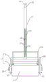
Fig. 1 is a schematic structural diagram of the present invention.
Fig. 2 is a schematic structural diagram of the side view of the present invention.
Fig. 3 is a schematic structural view of the mop head of the present invention.
Notations for reference numerals: the mop comprises a mop rod 1, a mop head 2, an installation fixing frame 3, a connection fixing rod 4, a connection side plate 5, an inner prism 6, a mop sleeve brush 7, a support rod shaft 8, a limiting hole 9, a turning knob 10, a limiting pin shaft 11, a through hole 12, an adjusting screw rod 13, a rotating hand wheel 14, a strip-shaped hole 15, a first spiral sleeve 16, a second spiral sleeve 17, a push rod 18, a fixing frame 19, an extrusion roller 20 and an extrusion spring 21.
Detailed Description
The present invention will be described in detail with reference to the following embodiments, wherein like or similar elements are designated by like reference numerals throughout the drawings or description, and wherein the shape, thickness or height of the various elements may be expanded or reduced in practical applications. The embodiments of the present invention are provided only for illustration, and not for limiting the scope of the present invention. Any obvious and obvious modifications or alterations to the present invention can be made without departing from the spirit and scope of the present invention.
Referring to fig. 1 to 3, in an embodiment of the present invention, a mop capable of being alternately used for three sides includes a mop rod 1 and a mop head 2 having two ends, the mop head 2 is mounted at the bottom end of the mop rod 1 through a mounting bracket 3, the mounting bracket 3 includes a connecting rod 4 having one end fixed to the bottom of the mop rod 1 and a connecting side plate 5 located at the end side of the mop rod 1, the connecting side plate 5 is an isosceles trapezoid structure, the bottom end of the connecting rod 4 is fixed to the top of the connecting side plate 5, the mop head 2 includes an inner prism 6 having an equilateral triangle structure in cross section and a mop brush 7 wrapped on the outer side wall of the inner prism 6, a support rod shaft 8 is fixed at the center of each of the two ends of the inner prism 6, the support rod shaft 8 is rotatably mounted on the connecting side plate 5 at the same side with the support rod shaft 8, a fastening assembly is further arranged between the connecting side plate 5 and the inner prism 6 and comprises three limiting holes 9 arranged on the inner prism 6 and three through holes 12 arranged on the connecting side plate 5, the three limiting holes 9 and the three through holes 12 are in one-to-one correspondence, and a limiting pin shaft 11 is inserted into each corresponding limiting hole 9 and each corresponding through hole 12, when the limiting pin shaft 11 is pulled out, the support shaft 8 is rotated to enable the mop head 2 to rotate, so that three side surfaces of the mop head 2 face downwards alternately to mop the ground, and only three surfaces are full of dust to clean the mop head, so that the number of times of cleaning is reduced, the efficiency of mopping the ground is improved, and corners of a wall body can be cleaned at the corners of the mop head 2;
two outsides of mop head 2 all are provided with squeezing mechanism, squeezing mechanism includes mount 19 and installs in the squeeze roll 20 of mount 19 bottom, and squeeze roll 20 avris supports presses the squeeze roll 20 at 2 avris of mop head, and the equal fixedly connected with catch bar 18 in two mount 19 upper ends, mop pole 1 is hollow structure and its internally mounted has accommodate the lead screw 13, installs first spiral shell 16 and second spiral shell 17 all screwed connection with it on accommodate the lead screw 13, and two bar holes 15 that set up on mop pole 1 pole wall are passed on two catch bar 18 tops articulate on first spiral shell 16 lateral wall, and the avris of first spiral shell 16 and second spiral shell 17 and mop pole 1 inner wall sliding fit, two the middle part of catch bar 18 all is connected on the lateral wall of second spiral shell 17 through extrusion spring 21, and then when accommodate the lead screw 13 and rotate, accessible and first spiral shell 16, The spiral cooperation of the second spiral sleeve 17 enables the push rod 18 to push the fixing frame 19 to move downwards and the squeezing roller 20 to squeeze the mop sleeve brush 7 under the elastic force action of the squeezing spring 21, so that water in the mop sleeve brush 7 is squeezed out, the mop head 2 can be further fastened, the operation is convenient and fast, and the rotating hand wheel 14 is installed at the top end of the adjusting screw rod 13.
The above description is only for the specific embodiments of the present disclosure, but the scope of the present disclosure is not limited thereto, and any person skilled in the art can easily conceive of the changes or substitutions within the technical scope of the present disclosure, and all the changes or substitutions should be covered within the scope of the present disclosure. Therefore, the protection scope of the present disclosure shall be subject to the protection scope of the claims.
Claims (5)
1. A mop capable of being alternately used on three sides comprises a mop rod (1) and a mop head (2) with two ends installed at the bottom end of the mop rod (1) through an installation fixing frame (3), and is characterized in that the installation fixing frame (3) comprises a connecting fixing rod (4) with one end fixed at the bottom of the mop rod (1) and a connecting side plate (5) located at the end side of the mop rod (1), the connecting side plate (5) is of an isosceles trapezoid structure, the bottom end of the connecting fixing rod (4) is fixed at the top of the connecting side plate (5), the mop head (2) comprises an inner prism (6) with an equilateral triangle structure in cross section and a mop sleeve brush (7) wrapped on the outer side wall of the inner prism (6), supporting rod shafts (8) are fixed at the centers of the two ends of the inner prism (6), and the supporting rod shafts (8) are rotatably installed on the connecting side plate (5, and a fastening assembly is also arranged between the connecting side plate (5) and the inner prism (6).
2. A mop usable in three-rotation according to claim 1, characterized in that said fastening assembly comprises three defining holes (9) provided on the inner prism (6) and three perforations (12) provided on the connecting side plate (5), the three defining holes (9) corresponding to the three perforations (12) one to one and each defining pin (11) being pierced in the corresponding defining hole (9) and perforation (12).
3. A mop usable as a three-way rotation according to claim 1, characterized in that the end of the support bar shaft (8) is also provided with a turning knob (10) for screwing the support bar shaft (8).
4. The mop capable of three-side alternate use according to claim 2, wherein the two outer sides of the mop head (2) are respectively provided with a squeezing mechanism, the squeezing mechanism comprises a fixing frame (19) and a squeezing roller (20) arranged at the bottom of the fixing frame (19), the side of the squeezing roller (20) is abutted against the squeezing roller (20) arranged at the side of the mop head (2), the upper ends of the two fixing frames (19) are respectively and fixedly connected with a push rod (18), the mop rod (1) is of a hollow structure, an adjusting screw rod (13) is arranged in the hollow structure, a first spiral sleeve (16) and a second spiral sleeve (17) which are respectively and spirally connected with the adjusting screw rod (13) are arranged on the adjusting screw rod (13), the top ends of the two push rods (18) penetrate through strip-shaped holes (15) arranged on the rod wall of the mop rod (1) and are hinged on the side wall of the first spiral sleeve (16), the side of the first spiral sleeve (16) and the second spiral sleeve (17) are, the middle parts of the two push rods (18) are connected to the side wall of the second spiral sleeve (17) through an extrusion spring (21).
5. A mop usable in three-dimensional alternation according to claim 4, wherein a rotating handwheel (14) is mounted on the top end of the adjusting screw (13).
Priority Applications (1)
| Application Number | Priority Date | Filing Date | Title |
|---|---|---|---|
| CN201920643768.9U CN210961812U (en) | 2019-05-07 | 2019-05-07 | Mop capable of being used by three sides alternately |
Applications Claiming Priority (1)
| Application Number | Priority Date | Filing Date | Title |
|---|---|---|---|
| CN201920643768.9U CN210961812U (en) | 2019-05-07 | 2019-05-07 | Mop capable of being used by three sides alternately |
Publications (1)
| Publication Number | Publication Date |
|---|---|
| CN210961812U true CN210961812U (en) | 2020-07-10 |
Family
ID=71455977
Family Applications (1)
| Application Number | Title | Priority Date | Filing Date |
|---|---|---|---|
| CN201920643768.9U Expired - Fee Related CN210961812U (en) | 2019-05-07 | 2019-05-07 | Mop capable of being used by three sides alternately |
Country Status (1)
| Country | Link |
|---|---|
| CN (1) | CN210961812U (en) |
Cited By (1)
| Publication number | Priority date | Publication date | Assignee | Title |
|---|---|---|---|---|
| CN111772546A (en) * | 2020-07-20 | 2020-10-16 | 常金华 | Four-side mixed mop |
-
2019
- 2019-05-07 CN CN201920643768.9U patent/CN210961812U/en not_active Expired - Fee Related
Cited By (2)
| Publication number | Priority date | Publication date | Assignee | Title |
|---|---|---|---|---|
| CN111772546A (en) * | 2020-07-20 | 2020-10-16 | 常金华 | Four-side mixed mop |
| CN111772546B (en) * | 2020-07-20 | 2021-06-22 | 常金华 | Four-side mixed mop |
Similar Documents
| Publication | Publication Date | Title |
|---|---|---|
| CN210961812U (en) | Mop capable of being used by three sides alternately | |
| CN208892433U (en) | A kind of dust collecting and floor mopping all-in-one machine | |
| CN203341677U (en) | Mop with multi-directional de-scaling property | |
| CN213345527U (en) | Mop is used in life convenient to it is clean | |
| CN209018639U (en) | One kind is exempted to hand-wash mop washing barrel | |
| CN203852315U (en) | Mop head capable of being folded and cleaned | |
| CN209661560U (en) | A kind of mop cleaning tool | |
| CN213309514U (en) | Mop with handle | |
| CN210408286U (en) | Novel washing-free electric mop | |
| CN214484432U (en) | Mop wringing device for cleaning toilet | |
| CN217659693U (en) | Novel handle of cleaning mop | |
| CN212186393U (en) | Integral type clearance ground ware | |
| CN215227320U (en) | Dirt-removing separating mop | |
| CN215424466U (en) | Hand-pulling hydraulic rebounding water-squeezing plate type mop | |
| CN209122101U (en) | A kind of double-faced flat-sheet mop cleaning tool with cleaning and dewatering structure | |
| CN211066451U (en) | Wide head water squeezing mop | |
| CN212234348U (en) | Mop head | |
| CN214527056U (en) | Clean collection device is used to earthworm hosepipe | |
| CN215738768U (en) | Double-roller broom made of washable viscous silica gel | |
| CN211022494U (en) | Water and dust absorption mop | |
| CN109567700A (en) | A kind of mop cleaning tool | |
| CN218247140U (en) | Non-washing mop | |
| CN211355273U (en) | Double-sided mopping mop | |
| CN201008541Y (en) | Water wringing pipe of colloidine mop head | |
| CN212755545U (en) | Environment-friendly cleaning barrel |
Legal Events
| Date | Code | Title | Description |
|---|---|---|---|
| GR01 | Patent grant | ||
| GR01 | Patent grant | ||
| CF01 | Termination of patent right due to non-payment of annual fee |
Granted publication date: 20200710 Termination date: 20210507 |
|
| CF01 | Termination of patent right due to non-payment of annual fee |