CN210940887U - CTP plate-making machine - Google Patents
CTP plate-making machine Download PDFInfo
- Publication number
- CN210940887U CN210940887U CN201921105303.4U CN201921105303U CN210940887U CN 210940887 U CN210940887 U CN 210940887U CN 201921105303 U CN201921105303 U CN 201921105303U CN 210940887 U CN210940887 U CN 210940887U
- Authority
- CN
- China
- Prior art keywords
- plate
- screw rod
- limiting
- version equipment
- flitch
- Prior art date
- Legal status (The legal status is an assumption and is not a legal conclusion. Google has not performed a legal analysis and makes no representation as to the accuracy of the status listed.)
- Expired - Fee Related
Links
Images


Landscapes
- Rotary Presses (AREA)
Abstract
The utility model relates to a CTP platemaking machine, including direct platemaking machine, dash version equipment and receive version equipment, the pan feeding end that dashes version equipment passes through the discharge end switch-on of conveyer belt and direct platemaking machine, it connects at the discharge end that dashes version equipment to receive version equipment, it is fixed with the receipts flitch that is used for collecting the printing plate to receive the version equipment including carrying tilting mechanism and receiving the work or material rest to receive the pan feeding end of version equipment, it is equipped with the spout on the receipts flitch, sliding connection has the slider in the spout, be fixed with the limiting plate on the slider, the figure of limiting plate and slider is two, two limiting plates are located the both sides of receiving the flitch, be equipped with on. The printing plate overturns through the roll-over stand and receives on the flitch, and the both sides of printing plate are located the holding tank, and the lateral wall of holding tank carries on spacingly to the printing plate, avoids the printing plate to drop from receiving the flitch.
Description
Technical Field
The utility model belongs to the technical field of lithography apparatus technique and specifically relates to a CTP plate-making machine is related to.
Background
The CTP plate-making machine is characterized in that after a plate is engraved by laser scanning, a latent image of an image is formed on a printing plate, and after the latent image is developed, the image information on a screen of an upper computer is restored on the printing plate and is directly printed by an offset printing machine. The plate-making machine is used for exposing a plate, the exposed plate is conveyed to the plate-making equipment by a mechanism for developing and cleaning, and the developed plate is received by the plate-receiving equipment.
Receive version equipment including carrying tilting mechanism and receipts flitch, the printing plate from dashing the version equipment back of coming out, on the flitch is received in the tilting of tilting mechanism, receive the flitch slope and place, because the printing plate has the washing liquid when coming out, it is heavier itself, do not have stop device on the receipts flitch, the printing plate upset is received and is dropped easily on the flitch, causes stained to the printing plate.
SUMMERY OF THE UTILITY MODEL
The utility model aims at providing a CTP plate-making machine is provided with stop device on its receipts flitch, can carry on spacingly to the printing plate, avoids the printing plate to drop from receiving the flitch.
The above object of the present invention can be achieved by the following technical solutions:
the utility model provides a CTP platemaking machine, includes direct platemaking machine, dashes version equipment and receives version equipment, the pan feeding end that dashes version equipment passes through the discharge end switch-on of conveyer belt and direct platemaking machine, receive version equipment and connect at the discharge end that dashes version equipment, receive version equipment including carrying tilting mechanism and receiving the work or material rest, it is fixed with the receipts flitch that is used for collecting the printing plate to slope on the work or material rest, be equipped with the spout on receiving the flitch, sliding connection has the slider in the spout, be fixed with the limiting plate on the slider, the figure of limiting plate and slider is two, and two limiting plates are located the both sides of receiving the flitch, are equipped with on receiving the flitch to be.
Through adopting above-mentioned technical scheme, the printing plate is from dashing the version equipment and coming out the back, on the flitch was received in the upset of flip structure, the both sides butt of limiting plate and printing plate, and the frictional force between limiting plate and the printing plate improves a holding power for the printing plate, makes the printing plate be difficult to drop from receiving the flitch, slides in the spout through driving piece adjusting block, and then adjusts the distance between the limiting plate, can carry on spacingly to not unidimensional printing plate.
The utility model discloses further set up to: the driving piece is a screw rod, positive and negative threads are arranged on the screw rod, the screw rod is rotatably connected with the material receiving plate, and the screw rod penetrates through the sliding block and is in threaded connection with the sliding block.
Through adopting above-mentioned technical scheme, have different screw threads on the lead screw, two sliders are connected with positive thread, reverse thread respectively, and when rotating the lead screw, two sliders are close to or keep away from simultaneously.
The utility model discloses further set up to: tilting mechanism includes upset motor, roll-over stand and support, the roll-over stand rotates through pivot and support to be connected, upset motor and support fixed connection, the output shaft and the pivot fixed connection of upset motor are equipped with first gear on the output shaft of upset motor, be equipped with the second gear on the lead screw, second gear and first gear engagement are connected, be equipped with the holding tank on the relative side of limiting plate, be formed with the passageway that supplies the printing plate business turn over between two limiting plates.
Through adopting above-mentioned technical scheme, the upset motor rotates and drives the pivot, and the pivot drives the roll-over stand upset for the roll-over stand is to receiving the flitch orientation upset with the printing plate on delivering to the flitch. When the roll-over stand is towards the direction of the material receiving plate, the first gear and the second gear drive the screw rod to rotate, the two sliding blocks are away from each other, the channel is enlarged, the printing plate enters the space between the limiting plates, and the two sides of the printing plate are positioned in the accommodating groove; when the material receiving plate direction was kept away from to the roll-over stand, two sliders were close to each other, and the passageway diminishes, and the width of passageway is less than the width of printing plate, and the printing plate can't come out from the passageway, and the lateral wall of holding tank carries on spacingly to the printing plate, avoids the printing plate to drop from receiving the material board.
The utility model discloses further set up to: and one end of the screw rod, which is far away from the second gear, is provided with a hand crank.
Through adopting above-mentioned technical scheme, when adjusting the distance between the slider, conveniently rotate the lead screw.
The utility model discloses further set up to: the second gear is provided with an installation barrel, the installation barrel is sleeved on the screw rod and is in sliding connection with the screw rod, and the installation barrel is provided with a fixing piece for fixing the position of the installation barrel.
Through adopting above-mentioned technical scheme, in the face of the printing plate of different specifications, need adjust the distance between the slider, pull down the second gear on the lead screw earlier, rotate the lead screw and just can adjust the distance of slider, can not influence upset motor and roll-over stand.
The utility model discloses further set up to: the fixing piece is a screw rod, a screw hole is formed in the installation barrel, the screw rod is in threaded connection with the screw hole, and the end portion of the screw rod is abutted to the screw rod.
Through adopting above-mentioned technical scheme, screw up the screw rod, the tip of screw rod supports tightly on the screw rod and makes the second gear fix on the lead screw, unscrews the screw rod and can dismantle the second gear.
The utility model discloses further set up to: the mounting barrel is provided with a limiting groove, the screw rod is provided with a limiting strip, and the limiting strip is matched and clamped with the limiting groove.
Through adopting above-mentioned technical scheme, the installation barrel drives the lead screw and rotates more stably, can not skid.
The utility model discloses further set up to: the screw rod is provided with a limiting piece, the limiting piece is abutted against the end part of the limiting strip, and the limiting piece is abutted against the end part of the installation barrel.
Through adopting above-mentioned technical scheme, when the installation second gear, spacing piece and the tip butt of installation barrel, second gear and first gear meshing connection, easy to assemble.
The utility model discloses further set up to: the vertical section of the material collecting plate is L-shaped, and a baffle is arranged at the bottom end of the material collecting plate.
Through adopting above-mentioned technical scheme, the baffle can provide the support for the printing plate, avoids the printing plate from receiving the bottom landing of material board.
To sum up, the utility model discloses following beneficial effect has: the printing plate overturns through the roll-over stand and receives on the flitch, and the both sides of printing plate are located the holding tank, and the lateral wall of holding tank carries on spacingly to the printing plate, avoids the printing plate to drop from receiving the flitch.
Drawings
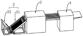
Fig. 1 is a schematic structural diagram of the present invention;
FIG. 2 is a schematic structural diagram of a plate receiving apparatus;
FIG. 3 is an enlarged schematic view of portion A of FIG. 2;
FIG. 4 is an enlarged schematic view of portion B of FIG. 2;
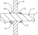
fig. 5 is a partial sectional view of the lead screw.
In the figure: 1. a direct platemaking machine; 2. a plate punching device; 3. plate receiving equipment; 31. conveying and turning mechanism; 311. turning over a motor; 312. a roll-over stand; 313. a support; 32. a material receiving frame; 4. a first gear; 5. a rotating shaft; 6. a material collecting plate; 61. a baffle plate; 62. a chute; 63. a slider; 64. a limiting plate; 65. accommodating grooves; 66. a channel; 7. a screw rod; 71. hand cranking; 72. a limiting strip; 73. a limiting sheet; 8. a second gear; 81. installing a cylinder body; 82. a limiting groove; 83. a screw hole; 9. a screw.
Detailed Description
The present invention will be described in further detail with reference to the accompanying drawings.
Referring to fig. 1, for the utility model discloses a CTP plate-making machine, including direct plate-making machine 1, towards version equipment 2 and receive version equipment 3, the pan feeding end that dashes version equipment 2 is put through the conveyer belt with the discharge end of direct plate-making machine 1, receives version equipment 3 and connects at the discharge end that dashes version equipment 2, and direct plate-making machine 1 exposes the printing plate, has exposed to carry again by the mechanism and has dashed version equipment 2 department and develop the washing, has developed to receive by receiving version equipment 3 and receive the material.
Referring to fig. 2 and 3, the plate receiving device 3 includes a conveying turnover mechanism 31 and a receiving rack 32, the turnover mechanism includes a turnover motor 311, a turnover frame 312 and a support 313, the turnover frame 312 is rotatably connected with the support 313 through a rotating shaft 5, the turnover motor 311 is a servo motor, the turnover motor 311 is fixedly connected with the support 313, an output shaft of the turnover motor 311 is fixedly connected with an end of the rotating shaft 5, and a first gear 4 is fixed on an output shaft of the turnover motor 311.
Referring to fig. 2 and 4, the material receiving rack 32 is obliquely fixed with a material receiving plate 6 for collecting printing plates, the vertical section of the material receiving plate 6 is L-shaped, and the bottom end of the material receiving plate 6 is fixed with a baffle 61. Receive and be provided with spout 62 on the flitch 6, sliding connection has slider 63 in the spout 62, is fixed with limiting plate 64 on the slider 63, and limiting plate 64 and slider 63's figure is two, and two limiting plates 64 are located the both sides of receiving flitch 6, and two limiting plates 64 and the surperficial sliding connection who receives flitch 6, two limiting plate 64 parallel arrangement are on receiving flitch 6, and the length of limiting plate 64 is less than the length of receiving flitch 6. The opposite side surfaces of the two limit plates 64 are provided with accommodating grooves 65, the accommodating grooves 65 are arranged along the length direction of the limit plates 64, a channel 66 for the printing plate to enter and exit is formed between the two limit plates 64, and the material receiving frame 32 is provided with a driving piece for driving the sliding block 63 to slide in the sliding groove 62.
Referring to fig. 4 and 5, the driving member is a screw rod 7, the middle of the screw rod 7 is a node, the two sides of the screw rod 7 are respectively provided with a positive thread and a negative thread, the screw rod 7 penetrates through the two sliding blocks 63, and the two sliding blocks 63 are respectively in threaded connection with the positive thread and the negative thread in a matching manner. The screw rod 7 is rotated, and the two sliding blocks 63 simultaneously move close to or away from each other in the sliding groove 62. The threaded part of the screw rod 7 is positioned in the chute 62, and two ends of the screw rod 7 extend out of the material collecting plate 6 and are rotationally connected with the material collecting plate 6. The end part of the screw rod 7 close to the overturning motor 311 is provided with a second gear 8, the second gear 8 is meshed with the first gear 4, the radiuses of the second gear 8 and the first gear 4 are the same, and a hand crank 71 is fixed at one end of the screw rod 7 far away from the second gear 8.
The second gear 8 is provided with an installation barrel 81, the installation barrel 81 is sleeved on the screw rod 7, the installation barrel 81 is connected with the screw rod 7 in a sliding mode, the inner side wall of the installation barrel 81 is provided with a limiting groove 82, the screw rod 7 is provided with a limiting strip 72, and the limiting strip 72 is matched with the limiting groove 82 in a clamping mode. The screw 7 is provided with a limiting sheet 73, the limiting sheet 73 is abutted against the end part of the limiting strip 72, and the limiting sheet 73 is abutted against the end part of the mounting cylinder 81. The mounting cylinder 81 is provided with a fixing piece for fixing the position of the mounting cylinder 81, the fixing piece is a screw 9, the mounting cylinder 81 is provided with a screw hole 83, the screw 9 is in threaded connection with the screw hole 83, and the end part of the screw 9 is abutted to the screw rod 7.
The implementation principle of the embodiment is as follows: after the printing plate is exposed through the direct plate-making machine 1 and is developed at the position of the plate-punching equipment 2, the printing plate is conveyed to the turnover frame 312 through the conveying belt, the turnover motor 311 is started, the turnover motor 311 drives the turnover frame 312 to turn over towards the direction of the material receiving plate 6, the turnover motor 311 drives the screw rod 7 to rotate simultaneously, the two limiting plates 64 are mutually far away, the channel 66 is enlarged, and the printing plate enters the material receiving plate 6. The reversing motor 311 reversely rotates, the reversing frame 312 reverses to the direction away from the material receiving plate 6 to return to the support 313, the screw rod 7 reversely rotates, the two limiting plates 64 are close to each other, the channel 66 is reduced, the two sides of the printing plate are located in the accommodating groove 65, the printing plate cannot come out from the channel 66 due to the fact that the width of the channel 66 is smaller than the width of the printing plate, and the situation that the printing plate drops from the material receiving plate 6 is avoided. When the distance between the limiting plates 64 is required to be adjusted for printing plates of different specifications, the second gear 8 is detached, the screw rod 7 is rotated, the distance between the limiting plates 64 is adjusted properly, then the second gear 8 is installed, and the second gear 8 and the first gear 4 are in aligned meshed connection. When the printing plate is taken out, the printing plate is pulled out in the extending direction of the housing tank 65.
The embodiment of this specific implementation mode is the preferred embodiment of the present invention, not limit according to this the utility model discloses a protection scope, so: all equivalent changes made according to the structure, shape and principle of the utility model are covered within the protection scope of the utility model.
Claims (9)
1. The utility model provides a CTP platemaking machine, includes direct platemaking machine (1), dashes version equipment (2) and receives version equipment (3), the pan feeding end that dashes version equipment (2) is put through the discharge end of conveyer belt with direct platemaking machine (1), receive version equipment (3) and connect the discharge end that dashes version equipment (2), receive version equipment (3) including carrying tilting mechanism (31) and receiving work or material rest (32), it is fixed with receipts material board (6) that are used for collecting the printing plate to slope in receiving work or material rest (32), its characterized in that: be equipped with spout (62) on receipts flitch (6), sliding connection has slider (63) in spout (62), be fixed with limiting plate (64) on slider (63), the figure of limiting plate (64) and slider (63) is two, and two limiting plate (64) are located the both sides of receiving flitch (6), are equipped with on receiving flitch (6) to be used for driving slider (63) gliding driving piece in spout (62).
2. The CTP plate-making machine according to claim 1, wherein: the driving piece is a screw rod (7), positive and negative threads are arranged on the screw rod (7), the screw rod (7) is rotatably connected with the material receiving plate (6), and the screw rod (7) penetrates through the sliding block (63) and is in threaded connection with the sliding block (63).
3. The CTP plate-making machine according to claim 2, wherein: turnover mechanism includes upset motor (311), roll-over stand (312) and support (313), roll-over stand (312) rotates through pivot (5) and support (313) and is connected, upset motor (311) and support (313) fixed connection, the output shaft and pivot (5) fixed connection of upset motor (311), be equipped with first gear (4) on the output shaft of upset motor (311), be equipped with second gear (8) on lead screw (7), second gear (8) and first gear (4) meshing are connected, be equipped with holding tank (65) on the relative side of limiting plate (64), be formed with passageway (66) that supply the printing plate business turn over between two limiting plate (64).
4. The CTP plate-making machine according to claim 3, wherein: and a hand crank (71) is arranged at one end of the screw rod (7) far away from the second gear (8).
5. The CTP plate-making machine according to claim 3, wherein: be equipped with installation barrel (81) on second gear (8), on lead screw (7) was located to installation barrel (81) cover, installation barrel (81) and lead screw (7) sliding connection, be equipped with the mounting that is used for fixed mounting barrel (81) position on installation barrel (81).
6. The CTP plate-making machine of claim 5, wherein: the fixing piece is a screw rod (9), a screw hole (83) is formed in the installation barrel (81), the screw rod (9) is in threaded connection with the screw hole (83), and the end portion of the screw rod (9) is abutted to the screw rod (7).
7. The CTP plate-making machine of claim 5, wherein: the mounting barrel is characterized in that a limiting groove (82) is formed in the mounting barrel (81), a limiting strip (72) is arranged on the screw rod (7), and the limiting strip (72) is in fit joint with the limiting groove (82).
8. The CTP plate-making machine according to claim 7, wherein: the screw rod (7) is provided with a limiting piece (73), the limiting piece (73) is abutted against the end part of the limiting strip (72), and the limiting piece (73) is abutted against the end part of the mounting cylinder (81).
9. The CTP plate-making machine according to claim 1, wherein: the vertical section of the material receiving plate (6) is L-shaped, and a baffle (61) is arranged at the bottom end of the material receiving plate (6).
Priority Applications (1)
| Application Number | Priority Date | Filing Date | Title |
|---|---|---|---|
| CN201921105303.4U CN210940887U (en) | 2019-07-13 | 2019-07-13 | CTP plate-making machine |
Applications Claiming Priority (1)
| Application Number | Priority Date | Filing Date | Title |
|---|---|---|---|
| CN201921105303.4U CN210940887U (en) | 2019-07-13 | 2019-07-13 | CTP plate-making machine |
Publications (1)
| Publication Number | Publication Date |
|---|---|
| CN210940887U true CN210940887U (en) | 2020-07-07 |
Family
ID=71371545
Family Applications (1)
| Application Number | Title | Priority Date | Filing Date |
|---|---|---|---|
| CN201921105303.4U Expired - Fee Related CN210940887U (en) | 2019-07-13 | 2019-07-13 | CTP plate-making machine |
Country Status (1)
| Country | Link |
|---|---|
| CN (1) | CN210940887U (en) |
Cited By (1)
| Publication number | Priority date | Publication date | Assignee | Title |
|---|---|---|---|---|
| CN111977416A (en) * | 2020-09-07 | 2020-11-24 | 杭州海洋电脑制版印刷有限公司 | CTP plate-making machine |
-
2019
- 2019-07-13 CN CN201921105303.4U patent/CN210940887U/en not_active Expired - Fee Related
Cited By (1)
| Publication number | Priority date | Publication date | Assignee | Title |
|---|---|---|---|---|
| CN111977416A (en) * | 2020-09-07 | 2020-11-24 | 杭州海洋电脑制版印刷有限公司 | CTP plate-making machine |
Similar Documents
| Publication | Publication Date | Title |
|---|---|---|
| DE69736452T2 (en) | Electrophotographic image forming apparatus with detachably mountable document reading device | |
| CN105050822B (en) | printer | |
| CN102794999B (en) | Printing equipment and Method of printing | |
| CN210940887U (en) | CTP plate-making machine | |
| CN205651812U (en) | Paper feed mechanism for receipt printer | |
| ATE277772T1 (en) | PRINTER UNIT FOR TRANSACTION DEVICE | |
| CN209813397U (en) | Printing machine | |
| EP0658822A3 (en) | Printing device duplexing mechanism and method therefor | |
| CN211684125U (en) | Stylus printer | |
| CN219859609U (en) | Printer capable of preventing printing deviation | |
| GB2175854A (en) | Supporting plate arrangement for document printers | |
| CN211617031U (en) | Limiting device of full-automatic laser holographic printing machine | |
| CN220009150U (en) | Board printing alignment auxiliary device | |
| JP2001083610A (en) | Negative carrier positioning device | |
| JP2008201068A (en) | Stamping equipment | |
| CN221873513U (en) | Screen printing equipment | |
| CN209938036U (en) | Novel printing device of digital printing machine | |
| KR101547068B1 (en) | Screen printer | |
| CN108749317B (en) | Multifunctional printing equipment | |
| JPH0138590Y2 (en) | ||
| JP2505414Y2 (en) | Film inversion guide structure for photo printing equipment | |
| CN209566654U (en) | A kind of Quick cleaning device for cylinders of printing press | |
| US9033490B2 (en) | Ink-jet recording apparatus | |
| JP2005308853A (en) | Image forming apparatus | |
| US10308045B2 (en) | Sheet conveyor and ink-jet recording apparatus |
Legal Events
| Date | Code | Title | Description |
|---|---|---|---|
| GR01 | Patent grant | ||
| GR01 | Patent grant | ||
| CF01 | Termination of patent right due to non-payment of annual fee | ||
| CF01 | Termination of patent right due to non-payment of annual fee |
Granted publication date: 20200707 |