CN210928419U - A communication data information processing device with dust-proof structure - Google Patents
A communication data information processing device with dust-proof structure Download PDFInfo
- Publication number
- CN210928419U CN210928419U CN201921677486.7U CN201921677486U CN210928419U CN 210928419 U CN210928419 U CN 210928419U CN 201921677486 U CN201921677486 U CN 201921677486U CN 210928419 U CN210928419 U CN 210928419U
- Authority
- CN
- China
- Prior art keywords
- frame
- dust
- slider
- information processing
- data information
- Prior art date
- Legal status (The legal status is an assumption and is not a legal conclusion. Google has not performed a legal analysis and makes no representation as to the accuracy of the status listed.)
- Expired - Fee Related
Links
Images


Landscapes
- Cooling Or The Like Of Electrical Apparatus (AREA)
Abstract
本实用新型公开了一种具有防尘结构的通信数据信息处理设备,包括外壳组件和散热组件,所述外壳组件包括工作架、连接架、丝杆、滑块、固定架和轴承,所述固定架设于所述工作架的一端,且与所述工作架焊接固定,所述丝杆设于所述固定架的下表面,且与所述固定架转动连接,所述滑块设于所述丝杆的外侧壁,电机带动丝杆转动,使得滑块沿着丝杆上下滑动,滑块带动通风架上下滑动,达到将冷风吹至工作架内的效果,使得工作架内的温度降低,达到散热的效果,在滑块上固定有吸尘板,滑块可以带动吸尘板上下滑动,吸尘板带动吸尘管滑动,使得吸尘机可以将工作架内的灰尘吸出,使得工作架保持干净,避免灰尘污染工作架内的通信数据信息处理设备。

The utility model discloses a communication data information processing device with a dust-proof structure, comprising a casing assembly and a heat dissipation assembly. The casing assembly includes a working frame, a connecting frame, a screw rod, a sliding block, a fixing frame and a bearing. It is erected on one end of the work frame and fixed by welding with the work frame. The screw rod is arranged on the lower surface of the fixing frame and is rotatably connected with the fixing frame. The slider is arranged on the wire On the outer side wall of the rod, the motor drives the screw rod to rotate, so that the slider slides up and down along the screw rod, and the slider drives the ventilation frame to slide up and down, so as to achieve the effect of blowing cold air into the work frame, which reduces the temperature in the work frame and achieves heat dissipation. There is a vacuum plate fixed on the slider, the slider can drive the vacuum plate to slide up and down, and the vacuum plate drives the vacuum pipe to slide, so that the vacuum cleaner can suck out the dust in the work frame and keep the work frame clean , to avoid dust contamination of the communication data information processing equipment in the work frame.
Description
技术领域technical field
本实用新型属于通信数据信息处理设备技术领域,具体涉及一种具有防尘结构的通信数据信息处理设备。The utility model belongs to the technical field of communication data information processing equipment, in particular to a communication data information processing equipment with a dustproof structure.
背景技术Background technique
目前现有的通信数据信息处理设备在使用时还有一些不足之处,例如,现有的通信数据信息处理设备在工作时,防尘除尘效果较差,灰尘难以清理会导致设备处理速度变慢,老化快,而且设备在工作时会产生大量的热量,使得设备处于高温的环境,高温会对设备内部的元件造成损害,降低了设备的使用寿命。At present, the existing communication data information processing equipment still has some shortcomings in use. For example, when the existing communication data information processing equipment is working, the dust and dust removal effect is poor, and the dust is difficult to clean, which will cause the equipment processing speed to slow down. , the aging is fast, and the equipment will generate a lot of heat during operation, making the equipment in a high temperature environment, and the high temperature will cause damage to the components inside the equipment and reduce the service life of the equipment.
实用新型内容Utility model content
本实用新型的目的在于提供一种具有防尘结构的通信数据信息处理设备,以解决上述背景技术中提出现有的通信数据信息处理设备在工作时,防尘除尘效果较差,灰尘难以清理会导致设备处理速度变慢,老化快,而且设备在工作时会产生大量的热量,使得设备处于高温的环境,高温会对设备内部的元件造成损害,降低了设备的使用寿命的问题。The purpose of this utility model is to provide a communication data information processing device with a dust-proof structure, so as to solve the problem that the existing communication data information processing device proposed in the above-mentioned background art has poor dust-proof and dust-removal effect, and the dust is difficult to clean. As a result, the processing speed of the equipment becomes slower, the aging is fast, and the equipment generates a lot of heat during operation, which makes the equipment in a high-temperature environment. The high temperature will cause damage to the components inside the equipment and reduce the service life of the equipment.
为实现上述目的,本实用新型提供如下技术方案:一种具有防尘结构的通信数据信息处理设备,包括外壳组件和散热组件,所述外壳组件包括工作架、连接架、丝杆、滑块、固定架和轴承,所述固定架设于所述工作架的一端,且与所述工作架焊接固定,所述丝杆设于所述固定架的下表面,且与所述固定架转动连接,所述滑块设于所述丝杆的外侧壁,且与所述丝杆滑动连接,所述连接架设于所述丝杆的下端,且与所述丝杆转动连接,所述轴承设于所述连接架的内部,且与所述轴承固定连接,所述散热组件包括支撑板、冷风机、通风管、通风架和电机,所述电机位于所述固定架的内部,且与所述固定架固定连接,所述支撑板设于所述工作架的一端,且靠近所述固定架远离所述工作架的一端,所述支撑板和所述工作架固定连接,所述冷风机设于所述支撑板的上表面,且与所述支撑板可拆卸连接,所述通风管的一端和所述冷风机固定连接,所述通风管的另一端和所述滑块固定连接,所述通风架位于所述滑块的内部,且与所述滑块固定连接,所述冷风机和所述电机均与外部电源电性连接。In order to achieve the above purpose, the present utility model provides the following technical solutions: a communication data information processing device with a dust-proof structure, comprising a shell assembly and a heat dissipation assembly, the shell assembly includes a working frame, a connecting frame, a screw rod, a slider, A fixing frame and a bearing, the fixing frame is installed on one end of the working frame and is welded and fixed with the working frame, and the screw rod is arranged on the lower surface of the fixing frame and is rotatably connected with the fixing frame, so The slider is arranged on the outer side wall of the screw rod and is slidably connected with the screw rod. The connection is erected on the lower end of the screw rod and is rotatably connected with the screw rod. The inside of the connecting frame is fixedly connected with the bearing, the heat dissipation assembly includes a support plate, a cooling fan, a ventilation pipe, a ventilation frame and a motor, and the motor is located inside the fixing frame and is fixed with the fixing frame The support plate is arranged at one end of the work frame, and is close to the end of the fixing frame away from the work frame, the support plate and the work frame are fixedly connected, and the cooling fan is arranged on the support The upper surface of the plate is detachably connected to the support plate, one end of the ventilation pipe is fixedly connected to the cooling fan, the other end of the ventilation pipe is fixedly connected to the slider, and the ventilation frame is located at the The inside of the slider is fixedly connected with the slider, and the air cooler and the motor are both electrically connected to an external power source.
优选的,所述外壳组件还包括吸尘板和连接板,所述连接板设于所述滑块的前表面,且与所述滑块固定连接,所述吸尘板设于所述连接板的内侧壁,且与所述连接板螺栓固定,所述散热组件还包括吸尘管和吸尘机,所述吸尘机设于所述工作架的前表面,且与所述工作架可拆卸连接,所述吸尘管的一端和所述吸尘机固定连接,所述吸尘管的另一端和所述吸尘板固定连接,所述吸尘机和外部电源电性连接。Preferably, the housing assembly further comprises a dust collecting plate and a connecting plate, the connecting plate is provided on the front surface of the slider and is fixedly connected with the sliding block, and the dust collecting plate is provided on the connecting plate The inner side wall of the frame is bolted and fixed with the connecting plate. The heat dissipation assembly also includes a vacuum pipe and a vacuum cleaner. The vacuum cleaner is arranged on the front surface of the work frame and is detachable from the work frame. One end of the vacuum cleaner is fixedly connected to the vacuum cleaner, the other end of the vacuum cleaner is fixedly connected to the vacuum cleaner, and the vacuum cleaner is electrically connected to an external power supply.
优选的,所述丝杆的数量为两个,且两个所述丝杆均分布于所述工作架的两端。Preferably, the number of the screw rods is two, and the two screw rods are distributed at both ends of the work frame.
优选的,所述通风架贯穿所述滑块,且与所述通风管固定连接。Preferably, the ventilation frame penetrates through the sliding block and is fixedly connected with the ventilation pipe.
优选的,所述吸尘管的数量为若干个,且若干个所述吸尘管均安装于所述吸尘板的内部。Preferably, the number of the dust suction pipes is several, and the plurality of the dust suction pipes are all installed inside the dust suction plate.
优选的,所述丝杆和所述电机的输出端固定连接。Preferably, the lead screw is fixedly connected to the output end of the motor.
优选的,所述轴承安装于所述丝杆的外侧壁,且与所述丝杆固定连接。Preferably, the bearing is mounted on the outer side wall of the screw rod and is fixedly connected with the screw rod.
与现有技术相比,本实用新型的有益效果是:本实用新型结构科学合理,使用安全方便,电机带动丝杆转动,使得滑块沿着丝杆上下滑动,滑块带动通风架上下滑动,达到将冷风吹至工作架内的效果,使得工作架内的温度降低,达到散热的效果,在滑块上固定有吸尘板,滑块可以带动吸尘板上下滑动,吸尘板带动吸尘管滑动,使得吸尘机可以将工作架内的灰尘吸出,使得工作架保持干净,避免灰尘污染工作架内的通信数据信息处理设备。Compared with the prior art, the beneficial effects of the utility model are as follows: the utility model has a scientific and reasonable structure, is safe and convenient to use, the motor drives the screw rod to rotate, the slider slides up and down along the screw rod, and the slider drives the ventilation frame to slide up and down, To achieve the effect of blowing cold air into the work frame, the temperature in the work frame is reduced, and the effect of heat dissipation is achieved. A vacuum plate is fixed on the slider, the slider can drive the vacuum plate to slide up and down, and the vacuum plate drives the vacuum. The tube slides, so that the vacuum cleaner can suck out the dust in the work frame, so that the work frame is kept clean, and the communication data information processing equipment in the work frame is prevented from being polluted by dust.
附图说明Description of drawings
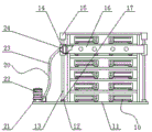
图1为本实用新型的正面结构示意图;Fig. 1 is the front structure schematic diagram of the present utility model;
图2为本实用新型的固定架内部结构意图;2 is a schematic diagram of the internal structure of the fixture of the present invention;
图3为本实用新型的吸尘机放大结构示意图;3 is a schematic view of the enlarged structure of the vacuum cleaner of the present invention;
图中:10、外壳组件;11、工作架;12、连接架;13、丝杆;14、滑块;15、固定架;16、吸尘板;17、轴承;18、连接板;20、散热组件;21、支撑板;22、冷风机;23、通风管;24、通风架;25、电机;26、吸尘管;27、吸尘机。In the figure: 10, shell assembly; 11, work frame; 12, connecting frame; 13, screw rod; 14, sliding block; 15, fixing frame; 16, dust collector; 17, bearing; 18, connecting plate; 20, Cooling assembly; 21, support plate; 22, air cooler; 23, ventilation pipe; 24, ventilation frame; 25, motor; 26, dust pipe; 27, vacuum cleaner.
具体实施方式Detailed ways
下面将结合本实用新型实施例中的附图,对本实用新型实施例中的技术方案进行清楚、完整地描述,显然,所描述的实施例仅仅是本实用新型一部分实施例,而不是全部的实施例。基于本实用新型中的实施例,本领域普通技术人员在没有做出创造性劳动前提下所获得的所有其他实施例,都属于本实用新型保护的范围。The technical solutions in the embodiments of the present utility model will be clearly and completely described below with reference to the accompanying drawings in the embodiments of the present utility model. Obviously, the described embodiments are only a part of the embodiments of the present utility model, rather than all the implementations. example. Based on the embodiments of the present invention, all other embodiments obtained by those of ordinary skill in the art without creative work fall within the protection scope of the present invention.
请参阅图1-图3,本实用新型提供一种具有防尘结构的通信数据信息处理设备技术方案:包括外壳组件10和散热组件20,外壳组件10包括工作架11、连接架12、丝杆13、滑块14、固定架15和轴承17,固定架15设于工作架11的一端,且与工作架11焊接固定,丝杆13设于固定架15的下表面,且与固定架15转动连接,滑块14设于丝杆13的外侧壁,且与丝杆13滑动连接,连接架12设于丝杆13的下端,且与丝杆13转动连接,轴承17设于连接架12的内部,且与轴承17固定连接,散热组件20包括支撑板21、冷风机22、通风管23、通风架24和电机25,电机25位于固定架15的内部,且与固定架15固定连接,支撑板21设于工作架11的一端,且靠近固定架15远离工作架11的一端,支撑板21和工作架11固定连接,冷风机22设于支撑板21的上表面,且与支撑板21可拆卸连接,通风管23的一端和冷风机22固定连接,通风管23的另一端和滑块14固定连接,通风架24位于滑块14的内部,且与滑块14固定连接,冷风机22和电机25均与外部电源电性连接。Please refer to FIG. 1 to FIG. 3 , the present utility model provides a technical solution of a communication data information processing device with a dust-proof structure: including a
为了使得吸尘板16和滑块14通过连接板18固定在一起,使得滑块14可以带动吸尘板16上下滑动,将吸尘机27接通外部电源,吸尘板16带动吸尘管26滑动,使得吸尘机27可以将工作架11内的灰尘吸出,使得工作架11保持干净,避免灰尘污染,本实施例中,优选的外壳组件10还包括吸尘板16和连接板18,连接板18设于滑块14的前表面,且与滑块14固定连接,吸尘板16设于连接板18的内侧壁,且与连接板18螺栓固定,散热组件20还包括吸尘管26和吸尘机27,吸尘机27设于工作架11的前表面,且与工作架11可拆卸连接,吸尘管26的一端和吸尘机27固定连接,吸尘管26的另一端和吸尘板16固定连接,吸尘机27和外部电源电性连接。In order to fix the
为了使得两个丝杆13上均设置有滑块14,两个滑块14同时下上滑动,保持同等的水平高度,两个滑块14对吸尘板16起到了支撑的作用,方便吸尘板16带动吸尘管26,达到吸收灰尘的效果,本实施例中,优选的丝杆13的数量为两个,且两个丝杆13均分布于工作架11的两端。In order to set the
为了使得冷风机22将冷风通过通风管23和通风架24吹至工作架11的内部,达到降低工作架11内的温度的效果,本实施例中,优选的通风架24贯穿滑块14,且与通风管23固定连接。In order to make the
为了使得达到充分吸尘的效果,多个吸尘机27带动吸尘管26进行吸收灰尘,多个吸尘管26均匀分布于吸尘板16的内部,本实施例中,优选的吸尘管26的数量为若干个,且若干个吸尘管26均安装于吸尘板16的内部。In order to achieve a sufficient effect of vacuuming, a plurality of
为了使得电机25带动丝杆13转动,使得滑块14沿着丝杆13上下滑动,滑块14带动通风架24上下滑动,本实施例中,优选的丝杆13和电机25的输出端固定连接。In order to make the
为了使得丝杆13和连接架12通过轴承17转动,方便丝杆13转动,达到带动滑块14上下滑动的效果,本实施例中,优选的轴承17安装于丝杆13的外侧壁,且与丝杆13固定连接。In order to make the
本实用新型的工作原理及使用流程:本实用新型安装好过后,工作人员将电机25接通外部电源,电机25带动丝杆13转动,使得滑块14沿着丝杆13上下滑动,滑块14带动通风架24上下滑动,将冷风机22接通外部电源,开启冷风机22,冷风机22将冷风通过通风管23和通风架24吹至工作架11的内部,达到降低工作架11内的温度的效果,吸尘板16和滑块14通过连接板18固定在一起,使得滑块14可以带动吸尘板16上下滑动,将吸尘机27接通外部电源,吸尘板16带动吸尘管26滑动,使得吸尘机27可以将工作架11内的灰尘吸出,使得工作架11保持干净,避免灰尘污染工作架11内。The working principle and use process of the utility model: after the utility model is installed, the staff connects the
尽管已经示出和描述了本实用新型的实施例,对于本领域的普通技术人员而言,可以理解在不脱离本实用新型的原理和精神的情况下可以对这些实施例进行多种变化、修改、替换和变型,本实用新型的范围由所附权利要求及其等同物限定。Although the embodiments of the present invention have been shown and described, it will be understood by those skilled in the art that various changes and modifications can be made to these embodiments without departing from the principles and spirit of the present invention , alternatives and modifications, the scope of the present invention is defined by the appended claims and their equivalents.
Claims (7)
Priority Applications (1)
| Application Number | Priority Date | Filing Date | Title |
|---|---|---|---|
| CN201921677486.7U CN210928419U (en) | 2019-10-09 | 2019-10-09 | A communication data information processing device with dust-proof structure |
Applications Claiming Priority (1)
| Application Number | Priority Date | Filing Date | Title |
|---|---|---|---|
| CN201921677486.7U CN210928419U (en) | 2019-10-09 | 2019-10-09 | A communication data information processing device with dust-proof structure |
Publications (1)
| Publication Number | Publication Date |
|---|---|
| CN210928419U true CN210928419U (en) | 2020-07-03 |
Family
ID=71368161
Family Applications (1)
| Application Number | Title | Priority Date | Filing Date |
|---|---|---|---|
| CN201921677486.7U Expired - Fee Related CN210928419U (en) | 2019-10-09 | 2019-10-09 | A communication data information processing device with dust-proof structure |
Country Status (1)
| Country | Link |
|---|---|
| CN (1) | CN210928419U (en) |
-
2019
- 2019-10-09 CN CN201921677486.7U patent/CN210928419U/en not_active Expired - Fee Related
Similar Documents
| Publication | Publication Date | Title |
|---|---|---|
| CN211513810U (en) | Heat dissipation dust collector for electromechanical device | |
| CN218426155U (en) | Metal product processing electric welding heat radiation structure | |
| CN211267328U (en) | An energy-saving outdoor communication air-cooled cabinet | |
| CN210137566U (en) | Heat dissipation device for power supply cabinet | |
| CN211454467U (en) | Computer machine case dust collector | |
| CN220585756U (en) | A dust-proof heat dissipation structure | |
| CN213578208U (en) | Adjustable titanium condenser | |
| CN211926221U (en) | Air cooling device for machining workpiece production | |
| CN211860898U (en) | Radiator convenient to clean | |
| CN210693216U (en) | A protection peripheral for power marketing power metering equipment | |
| CN120315550A (en) | A GPU group automatic cleaning mechanism | |
| CN219351680U (en) | Solar photovoltaic panel with good heat dissipation performance | |
| CN218017426U (en) | Noise treatment and heat dissipation device for high-precision machining center | |
| CN217656902U (en) | Quick dust collector of switch board | |
| CN118736980A (en) | Ultra-thin touch-controlled liquid crystal display screen | |
| CN118409640A (en) | Heat dissipation device for Internet data server and heat dissipation method thereof | |
| CN210878569U (en) | Drilling device for aluminum alloy plate of radiator | |
| CN209728629U (en) | A kind of air channel structure and the electronic equipment using the air duct | |
| CN211857385U (en) | A removable computer case | |
| CN218735677U (en) | Electrical equipment dust collector | |
| CN220873083U (en) | A voice safety reminder for water conservancy construction sites | |
| CN118659208B (en) | Electric power cabinet based on thing networking | |
| CN224165002U (en) | Thing networking case with heat radiation structure | |
| CN221434201U (en) | Server clearance mechanism | |
| CN223908419U (en) | Centrifugal fan with adjustable impeller external diameter |
Legal Events
| Date | Code | Title | Description |
|---|---|---|---|
| GR01 | Patent grant | ||
| GR01 | Patent grant | ||
| CF01 | Termination of patent right due to non-payment of annual fee | ||
| CF01 | Termination of patent right due to non-payment of annual fee |
Granted publication date: 20200703 |