CN210920456U - Sealing structure for water supply and drainage pipe fitting - Google Patents
Sealing structure for water supply and drainage pipe fitting Download PDFInfo
- Publication number
- CN210920456U CN210920456U CN201922186697.7U CN201922186697U CN210920456U CN 210920456 U CN210920456 U CN 210920456U CN 201922186697 U CN201922186697 U CN 201922186697U CN 210920456 U CN210920456 U CN 210920456U
- Authority
- CN
- China
- Prior art keywords
- sleeve
- pipe
- water supply
- screw holes
- drainage pipe
- Prior art date
- Legal status (The legal status is an assumption and is not a legal conclusion. Google has not performed a legal analysis and makes no representation as to the accuracy of the status listed.)
- Active
Links
Images


Abstract
The utility model discloses a seal structure for giving drainage pipe fitting, including adapter sleeve and tube head cover, the adapter sleeve includes ring sleeve board, outer tube housing and inner tube housing, and the middle part of ring sleeve board one side terminal surface link up and has seted up logical groove, the periphery welding that leads to the groove on the ring sleeve board both sides terminal surface has the inner tube housing, and the periphery welding cover of inner tube housing is equipped with outer tube housing on the ring sleeve board both sides terminal surface, and it has the tube head cover to peg graft between the outside of the inside of outer tube housing and inner tube housing, the one end welding of tube head cover has the retaining ring, and retaining ring and drainage pipe port welded fastening. The utility model discloses can improve the leakproofness of pipeline, make things convenient for the later stage to use the installation, and then improve the sealed effect of pipe connection and the compactness of connection.
Description
Technical Field
The utility model relates to a water drainage pipe spare seals technical field, especially relates to a seal structure for giving water drainage pipe spare.
Background
Water supply and drainage pipeline engineering is the pipe-line system engineering of carrying and distributing industry feedwater and domestic drinking water and collection, carry and discharge industrial waste water, domestic sewage and rainwater, current water supply and drainage pipeline is for the inside rivers of control pipeline, set up the control valve in water supply and drainage pipeline usually, the break-make that is arranged in controlling water supply and drainage pipeline for rivers, two ports of rivers control valve, be connected with water supply and drainage pipeline through the ring flange usually, in order to guarantee water supply and drainage pipeline's leakproofness during the connection, be used for keeping connecting the leakproofness through setting up sealed rubber pad between the ring flange, but because the rubber pad passes through the ring flange extrusion realization sealed, expose outside for a long time and rivers wash down the rubber pad easy ageing, sealed effect can descend.
Therefore, a sealing structure for water supply and drainage pipe fittings is needed, which can improve the sealing performance of the pipeline, facilitate later use and installation, and further improve the sealing effect of pipeline connection and the connection tightness.
SUMMERY OF THE UTILITY MODEL
An object of the utility model is to provide a seal structure for giving water drainage pipe fitting aims at improving current ring flange and giving water drainage pipe connection, in order to guarantee for water drainage pipe's leakproofness during the connection, is used for keeping connecting the leakproofness through setting up sealing rubber pad between the ring flange, but because the rubber pad passes through the ring flange extrusion and realizes sealing, exposes for a long time outside and rivers erode down the easy ageing of rubber pad, problem that sealed effect can descend.
The utility model discloses a realize like this:
the utility model provides a seal structure for giving drainage pipe fitting, including adapter sleeve and tube head cover, the adapter sleeve includes ring sleeve board, outer pipe box and inner pipe box, and the middle part of ring sleeve board one side end face link up and has seted up logical groove, the periphery welding that leads to the groove on the ring sleeve board both sides end face has interior pipe box, and the periphery welding cover of interior pipe box on the ring sleeve board both sides end face is equipped with outer pipe box, and it has the tube head cover to peg graft between the outside of the inside of outer pipe box and inner pipe box, the one end welding of tube head cover has the catch ring, and catch ring and drainage pipe port welded fastening.
Furthermore, the outer circumferential surface of the pipe head sleeve uniformly penetrates through the inner wall along the circumferential direction to be provided with limiting screw holes, the outer diameter of the pipe head sleeve is smaller than the inner diameter of the outer pipe sleeve, and the inner diameter of the pipe head sleeve is larger than the outer diameter of the inner pipe sleeve.
And then evenly run through the inner wall along the circumferencial direction on the outside periphery of pipe head cover and seted up spacing screw for spacing connecting pipe head cover and adapter sleeve, the external diameter of pipe head cover is less than the internal diameter of outer pipe box simultaneously, and the internal diameter of pipe head cover is greater than the external diameter of inner tube box, conveniently pegs graft and fix between outer pipe box and inner pipe box.
Furthermore, the outer circumferential surface of the outer sleeve uniformly penetrates through the inner wall along the circumferential direction and is provided with connecting screw holes, and locking screw rods are arranged in the connecting screw holes in a threaded mode.
And then evenly run through the inner wall and seted up the connection screw on the outer periphery of outer pipe box along the circumferencial direction to equal threaded installation has the locking screw in the connection screw, thereby installation connection outer pipe box and tube head cover.
Furthermore, the outer circumferential surface of the inner pipe sleeve uniformly penetrates through the inner wall along the circumferential direction and is provided with a locking screw hole, and the locking screw hole is opposite to the connecting screw hole and the limiting screw hole.
And then evenly run through the inner wall and seted up the locking screw on the outside periphery through inner tube cover along the circumferencial direction, and the locking screw sets up with connecting screw and spacing screw relatively for the installation is connected outer pipe cover and pipe headgear.
Furthermore, the pipe head sleeve is connected and fastened with the outer pipe sleeve and the inner pipe sleeve through a locking screw penetrating connection screw hole, a limiting screw hole and a locking screw hole.
And then pass through locking screw through connection screw, spacing screw and locking screw through pipe headgear and outer pipe box and inner tube cover and be connected the fastening to guarantee the stability of installation use.
Further, rubber sleeves are bonded on the inner wall of the outer pipe sleeve and the outer wall of the inner pipe sleeve.
And then all bond rubber sleeve on the inner wall through outer pipe sleeve and the inner pipe sleeve outer wall for improve the compactness of being connected with drainage pipe port department and valve port department pipe cap.
Compared with the prior art, the beneficial effects of the utility model are that: when the sealing structure of the water supply and drainage pipe fitting is used for connecting a water pipe and a sealing valve or two pipelines in butt joint, firstly, a pipe head sleeve is welded at the port part of the drainage pipe and the port part of the valve which need to be in butt joint or be connected, then, the pipe head sleeves at the port part of the drainage pipe and the port part of the valve are arranged between the two pipe head sleeves, inner pipe sleeves are welded at the through groove port parts at the two ends of the connecting sleeve, the outer pipe sleeves are welded at the periphery of the inner pipe sleeves on the end surfaces of the two sides of a ring sleeve plate, the outer diameter of the pipe head sleeves is smaller than the inner diameter of the outer pipe sleeves, the inner diameter of the pipe head sleeves is larger than the outer diameter of the inner pipe sleeves, the pipe head sleeves are inserted between the inside of the outer pipe sleeves and the outside of the inner pipe sleeves, then, and then can improve the leakproofness of pipeline, make things convenient for the later stage to use the installation, and then improve the sealed effect of tube coupling and the compactness of connecting.
Drawings
In order to more clearly illustrate the technical solutions of the embodiments of the present invention, the drawings that are required to be used in the embodiments will be briefly described below, it should be understood that the following drawings only illustrate some embodiments of the present invention, and therefore should not be considered as limiting the scope, and for those skilled in the art, other related drawings can be obtained according to the drawings without inventive efforts.
Fig. 1 is a schematic view of the overall structure of the present invention;
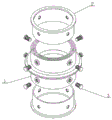
FIG. 2 is a schematic view of the exploded structure of the present invention;
fig. 3 is an explosion structure diagram of the connecting sleeve in the embodiment of the present invention;
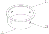
FIG. 4 is a schematic structural view of a sleeve pipe according to an embodiment of the present invention;
fig. 5 is a schematic view of the connection structure of the connection sleeve, the outer sleeve and the inner sleeve in the embodiment of the present invention.
In the figure: 1. connecting sleeves; 11. a ring sleeve plate; 12. an outer pipe sleeve; 13. an inner pipe sleeve; 14. a connecting screw hole; 15. a rubber sleeve; 111. a through groove; 131. locking screw holes; 2. a pipe head sleeve; 21. a baffle ring; 22. a limiting screw hole; 3. and locking the screw rod.
Detailed Description
To make the objects, technical solutions and advantages of the embodiments of the present invention clearer, the drawings of the embodiments of the present invention are combined to clearly and completely describe the technical solutions of the embodiments of the present invention, and obviously, the described embodiments are some embodiments of the present invention, not all embodiments. Based on the embodiments in the present invention, all other embodiments obtained by a person skilled in the art without creative work belong to the protection scope of the present invention. Thus, the following detailed description of the embodiments of the present invention, presented in the accompanying drawings, is not intended to limit the scope of the invention, as claimed, but is merely representative of selected embodiments of the invention. Based on the embodiments in the present invention, all other embodiments obtained by a person skilled in the art without creative work belong to the protection scope of the present invention.
Referring to fig. 1, 2, 3, 4 and 5, a sealing structure for water supply and drainage pipe fittings comprises a connecting sleeve 1 and a pipe head sleeve 2, wherein the connecting sleeve 1 comprises a ring sleeve plate 11, an outer pipe sleeve 12 and an inner pipe sleeve 13, a through groove 111 is formed in the middle of one side end face of the ring sleeve plate 11 in a penetrating manner, the inner pipe sleeve 13 is welded on the periphery of the through groove 111 on the two side end faces of the ring sleeve plate 11, the outer pipe sleeve 12 is welded on the periphery of the inner pipe sleeve 13 on the two side end faces of the ring sleeve plate 11 in a welding manner, the pipe head sleeve 2 is inserted between the inside of the outer pipe sleeve 12 and the outside of the inner pipe sleeve 13, a retaining ring 21 is welded at one end of the pipe head sleeve 2, and the retaining.
When the sealing structure of the water supply and drainage pipe fitting is used for connecting a water pipe and a sealing valve or two pipelines in butt joint, firstly, a pipe head sleeve 2 is welded at the port of a drainage pipeline and the port of the valve, which need to be in butt joint or connected with the valve, then a connecting sleeve 1 is arranged between the pipe head sleeves 2 at the port of the drainage pipeline and the port of the valve, inner pipe sleeves 13 are welded at the port of through grooves 111 at the two ends of the connecting sleeve 1, an outer pipe sleeve 12 is welded on the periphery of the inner pipe sleeve 13 on the end surfaces at the two sides of a ring sleeve plate 11, the outer diameter of the pipe head sleeve 2 is smaller than the inner diameter of the outer pipe sleeve 12, the inner diameter of the pipe head sleeve 2 is larger than the outer diameter of the inner pipe sleeve 13, the pipe head sleeve 2 is inserted between the inner part of the outer pipe sleeve 12 and the outer part of the inner pipe sleeve 13, and then the locking, thereby the installation of accomplishing the pipeline is sealed, and then can improve the leakproofness of pipeline, makes things convenient for the later stage to use the installation, and then improves the sealed effect of pipe connection and the compactness of connection.
Referring to fig. 4, the outer circumferential surface of the tube head sleeve 2 is provided with limit screw holes 22 uniformly penetrating the inner wall along the circumferential direction, the outer diameter of the tube head sleeve 2 is smaller than the inner diameter of the outer tube sleeve 12, and the inner diameter of the tube head sleeve 2 is larger than the outer diameter of the inner tube sleeve 13.
And then evenly run through the inner wall along the circumferencial direction on the outside periphery of pipe head cover 2 and seted up spacing screw 22 for spacing connecting pipe head cover 2 and adapter sleeve 1, the external diameter of pipe head cover 2 is less than the internal diameter of outer pipe sleeve 12 simultaneously, and the internal diameter of pipe head cover 2 is greater than the external diameter of inner pipe sleeve 13, conveniently pegs graft and fix between outer pipe sleeve 12 and inner pipe sleeve 13.
Referring to fig. 3, the outer circumferential surface of the outer jacket 12 is uniformly penetrated through the inner wall along the circumferential direction to form connection screw holes 14, and locking screws 3 are threadedly mounted in the connection screw holes 14.
And then evenly run through the inner wall and seted up connection screw 14 along the circumferencial direction on the outer periphery of outer pipe sleeve 12 to equal threaded mounting has locking screw 3 in the connection screw 14, thereby installation connection outer pipe sleeve 12 and tube head cover 2.
Referring to fig. 5, the outer circumferential surface of the inner sleeve 13 is uniformly penetrated through the inner wall along the circumferential direction to form locking screw holes 131, and the locking screw holes 131 are disposed opposite to the connecting screw holes 14 and the limiting screw holes 22.
And then evenly run through the inner wall and seted up locking screw 131 along the circumferencial direction on the outside periphery through inner tube cover 13, and locking screw 131 sets up with connecting screw 14 and spacing screw 22 relatively for the installation is connected outer pipe cover 12 and tube head cover 2.
Referring to fig. 5, the tube head sleeve 2 is fixedly connected to the outer tube sleeve 12 and the inner tube sleeve 13 through the locking screw 3 passing through the connecting screw hole 14, the limiting screw hole 22 and the locking screw hole 131.
And then through the pipe headgear 2 with outer pipe casing 12 and inner pipe casing 13 through locking screw 3 through connection screw 14, spacing screw 22 and locking screw 131 be connected the fastening to guarantee the stability of installation use.
Referring to fig. 3, rubber sleeves 15 are adhered to the inner wall of the outer jacket 12 and the outer wall of the inner jacket 13.
And then all bond rubber sleeve 15 on the inner wall through outer pipe casing 12 and the outer wall of inner pipe casing 13 for improve the compactness of being connected with drainage pipe port department and valve port department pipe end cover 2.
The working principle is as follows: when the sealing structure of the water supply and drainage pipe fitting is used for connecting a water pipe and a sealing valve or two pipelines in butt joint, firstly, a pipe head sleeve 2 is welded at the port part of a drainage pipeline and the port part of the valve, which need to be in butt joint or connected with the valve, then a connecting sleeve 1 is arranged between the pipe head sleeves 2 at the port part of the drainage pipeline and the port part of the valve, inner pipe sleeves 13 are welded at the port parts of through grooves 111 at two ends of the connecting sleeve 1, an outer pipe sleeve 12 is welded on the periphery of the inner pipe sleeve 13 on the end surfaces at two sides of a ring sleeve plate 11, the outer diameter of the pipe head sleeve 2 is smaller than the inner diameter of the outer pipe sleeve 12, the inner diameter of the pipe head sleeve 2 is larger than the outer diameter of the inner pipe sleeve 13, the pipe head sleeve 2 is inserted between the inner part of the outer pipe sleeve 12 and the outer part of the inner pipe sleeve 13, thereby the installation of accomplishing the pipeline is sealed, and then can improve the leakproofness of pipeline, makes things convenient for the later stage to use the installation, and then improves the sealed effect of pipe connection and the compactness of connection.
The device obtained through the design can basically meet the requirements of improving the sealing property of a pipeline, facilitating later-stage use and installation, further improving the sealing effect of pipeline connection and the tightness of connection, and further improving the purpose of further improving the functions of the sealing structure of the water supply and drainage pipe fitting.
The above description is only a preferred embodiment of the present invention and is not intended to limit the present invention, and various modifications and changes may be made by those skilled in the art. Any modification, equivalent replacement, or improvement made within the spirit and principle of the present invention should be included in the protection scope of the present invention.
Claims (6)
1. The utility model provides a seal structure for plumbing pipe fitting, includes adapter sleeve (1) and tube head cover (2), its characterized in that: adapter sleeve (1) is including ring cover board (11), outer tube sleeve (12) and inner tube sleeve (13), and link up the middle part of ring cover board (11) one side terminal surface and seted up logical groove (111), the periphery welding that leads to groove (111) on ring cover board (11) both sides terminal surface has inner tube sleeve (13), and the periphery welding cover of inner tube sleeve (13) is equipped with outer tube sleeve (12) on ring cover board (11) both sides terminal surface, and pegs graft between the outside of the inside of outer tube sleeve (12) and inner tube sleeve (13) has pipe cover (2), the one end welding of pipe cover (2) has fender ring (21), and keeps off ring (21) and drainage pipe port welded fastening.
2. A sealing structure for water supply and drainage pipe fittings according to claim 1, wherein the outer circumferential surface of the pipe head sleeve (2) is provided with limit screw holes (22) uniformly penetrating through the inner wall along the circumferential direction, the outer diameter of the pipe head sleeve (2) is smaller than the inner diameter of the outer pipe sleeve (12), and the inner diameter of the pipe head sleeve (2) is larger than the outer diameter of the inner pipe sleeve (13).
3. A sealing structure for a water supply and drainage pipe fitting according to claim 2, wherein the outer circumferential surface of the outer sleeve (12) is provided with connecting screw holes (14) uniformly penetrating through the inner wall along the circumferential direction, and the locking screws (3) are threadedly mounted in the connecting screw holes (14).
4. A sealing structure for a water supply and drainage pipe fitting according to claim 3, wherein the outer circumferential surface of the inner pipe sleeve (13) is provided with locking screw holes (131) uniformly penetrating the inner wall along the circumferential direction, and the locking screw holes (131) are arranged opposite to the connecting screw holes (14) and the limit screw holes (22).
5. A sealing structure for a water supply and drainage pipe fitting as claimed in claim 4, characterized in that the pipe head sleeve (2) is fixedly connected with the outer pipe sleeve (12) and the inner pipe sleeve (13) through a locking screw (3) through a connecting screw hole (14), a limiting screw hole (22) and a locking screw hole (131).
6. A sealing structure for a water supply and drainage pipe as claimed in claim 5, wherein rubber sleeves (15) are adhered to the inner wall of the outer pipe sleeve (12) and the outer wall of the inner pipe sleeve (13).
Priority Applications (1)
| Application Number | Priority Date | Filing Date | Title |
|---|---|---|---|
| CN201922186697.7U CN210920456U (en) | 2019-12-09 | 2019-12-09 | Sealing structure for water supply and drainage pipe fitting |
Applications Claiming Priority (1)
| Application Number | Priority Date | Filing Date | Title |
|---|---|---|---|
| CN201922186697.7U CN210920456U (en) | 2019-12-09 | 2019-12-09 | Sealing structure for water supply and drainage pipe fitting |
Publications (1)
| Publication Number | Publication Date |
|---|---|
| CN210920456U true CN210920456U (en) | 2020-07-03 |
Family
ID=71350855
Family Applications (1)
| Application Number | Title | Priority Date | Filing Date |
|---|---|---|---|
| CN201922186697.7U Active CN210920456U (en) | 2019-12-09 | 2019-12-09 | Sealing structure for water supply and drainage pipe fitting |
Country Status (1)
| Country | Link |
|---|---|
| CN (1) | CN210920456U (en) |
-
2019
- 2019-12-09 CN CN201922186697.7U patent/CN210920456U/en active Active
Similar Documents
| Publication | Publication Date | Title |
|---|---|---|
| CN210920456U (en) | Sealing structure for water supply and drainage pipe fitting | |
| CN207921556U (en) | The quick sealing rubber ring of circular hole take over road spigot-and-socket | |
| CN215000013U (en) | Anticorrosion chemical industry high pressure line connects | |
| CN213236436U (en) | Connecting device for municipal drainage pipeline | |
| CN213206855U (en) | Large-diameter reinforced concrete drain pipe connecting structure | |
| CN212537058U (en) | Building drainage pipe connects adjusting device | |
| CN212480418U (en) | Novel pipeline structure of plugging into | |
| CN205048059U (en) | External seal formula PE pipe connection | |
| CN209943726U (en) | Corrosion-proof leak-proof hydraulic pipe joint | |
| CN207018719U (en) | A kind of plastic union pipe head seal | |
| CN205745739U (en) | A kind of pipe fitting carrying sealing device | |
| CN216867793U (en) | Pressure pipe connecting device | |
| CN211203234U (en) | Valve pipeline connecting device with good sealing performance | |
| CN220688369U (en) | Quick-inserting PE drain pipe | |
| CN210950326U (en) | Flexible composite lining pipe connecting device | |
| CN210687344U (en) | Water supply and drainage engineering sewage pipes | |
| CN215371502U (en) | 90-degree elbow pipe fitting with side inspection port | |
| CN205534699U (en) | Circumscribed buckle structure | |
| CN212776073U (en) | Connecting assembly for stainless steel water pipe | |
| CN212960345U (en) | A pipeline for blowdown for environmental protection engineering | |
| CN214618284U (en) | Combined pipe joint with good sealing effect | |
| CN216843554U (en) | Device for repairing cement pipe socket | |
| CN212178164U (en) | Metal pipeline convenient to connect | |
| CN214662685U (en) | Water supply and drainage pipeline connector | |
| CN211288915U (en) | Metal elastic sealing butterfly valve with multi-layer sealing |
Legal Events
| Date | Code | Title | Description |
|---|---|---|---|
| GR01 | Patent grant | ||
| GR01 | Patent grant |