CN210907633U - Punching device of chain plate - Google Patents
Punching device of chain plate Download PDFInfo
- Publication number
- CN210907633U CN210907633U CN201921637350.3U CN201921637350U CN210907633U CN 210907633 U CN210907633 U CN 210907633U CN 201921637350 U CN201921637350 U CN 201921637350U CN 210907633 U CN210907633 U CN 210907633U
- Authority
- CN
- China
- Prior art keywords
- plate
- push
- chain
- punching
- chain plate
- Prior art date
- Legal status (The legal status is an assumption and is not a legal conclusion. Google has not performed a legal analysis and makes no representation as to the accuracy of the status listed.)
- Active
Links
Images


Landscapes
- Perforating, Stamping-Out Or Severing By Means Other Than Cutting (AREA)
Abstract
The utility model relates to a link joint processingequipment especially relates to a punching device to link joint. The utility model provides a punching device of link joint, includes the frame, is equipped with the workstation in the frame, is equipped with the link joint on the workstation and deposits the mechanism, and the link joint in the mechanism is deposited to the link joint is carried to punching press mechanism below by feed mechanism, and punching press mechanism includes drift, cope match-plate pattern and lower bolster, and the cope match-plate pattern is located the lower bolster top, and the drift pegs graft in the guiding hole in the cope match-plate pattern, is equipped with the waste material export in the below of lower bolster, and the drift is in the guiding hole all the time at the motion in. The utility model provides a punching device of a chain plate, which has simple structure, good punching effect of the chain plate, smooth punched hole without burr and high punching verticality precision of the chain plate; the technical problems that the equipment structure is complex, the chain plate punching effect is poor, burrs exist in punching, and the precision is not enough in the prior art are solved.
Description
Technical Field
The utility model relates to a link joint processingequipment especially relates to a device that punches a hole to the link joint.
Background
Chain transmission is a transmission mode frequently used in the existing transmission mechanism, a chain is used as a main component of the chain transmission, and the molding structure of each component can influence the operation condition of the final chain. The chain is composed of chain plates, rollers and pin shafts. Two parallel through holes are needed to be processed on the chain plate, and a pin shaft is connected in the through holes in a penetrating mode, so that one joint of the chain is assembled, and then all the joints are connected into a complete chain. After a punch on a punch presses a pin hole, the punched pin hole is often burred, a good bright belt cannot be obtained, the quality of chain sheet punching is influenced, and the vertical matching degree of a chain shaft of a chain and the chain sheet pin hole is also influenced. In the machining of mechanical parts, in order to improve the bright strip of the punched hole, there are generally two ways: one is to modify the blank by using a file and the like after blanking, the mode has low efficiency and large labor intensity, and the precision cannot be ensured; the other method is to change the punch into a combined type, namely, the lower end of the punch is a punching part and the upper end of the punching part is a trimming part, but the combined type punch needs to correspondingly improve the dimensions of the depth and the like of a female die of a stamping die, the time for modifying the power consumption of the die is longer, the cost is higher, in addition, because the thickness and the shape of the chain sheet of the chain are smaller, the whole strength of the chain sheet can be influenced by adopting the mode for blanking, and the precision and the quality of the chain sheet blanking are poorer. When current link joint punches a hole, generally need the manual work to place the link joint and carry out manual fixing on the lower die, then punch a hole, its inefficiency, the hand labor is big moreover, and degree of automation is low, need adopt fluid lubrication when the link joint punches a hole moreover, and the lubrication needs other fluid pipe to refuel to the link joint, and its external oil pipe and liquid outlet are used troublesome.
Disclosure of Invention
The utility model provides a punching device of a chain plate, which has simple structure, good punching effect of the chain plate, smooth punched hole without burr and high punching verticality precision of the chain plate; the technical problems that the equipment structure is complex, the chain plate punching effect is poor, burrs exist in punching, and the precision is not enough in the prior art are solved.
The above technical problem of the present invention is solved by the following technical solutions: the utility model provides a punching device of link joint, includes the frame, is equipped with the workstation in the frame, is equipped with the link joint on the workstation and deposits the mechanism, and the link joint in the mechanism is deposited to the link joint is carried to punching press mechanism below by feed mechanism, and punching press mechanism includes drift, cope match-plate pattern and lower bolster, and the cope match-plate pattern is located the lower bolster top, and the drift pegs graft in the guiding hole in the cope match-plate pattern, is equipped with the waste material export in the below of lower bolster, and the drift is in the guiding hole all the time at the motion in. The whole movement stroke of the punch moves in the holes communicated with the upper template and the lower template, the radial swing offset of the punch is limited, and the movement axial direction of the punch is ensured, so that the punching precision is improved, and the punching verticality on the chain plate is better. The feeding mechanism pushes the chain plates in the chain plate storage mechanism to move towards the chain plate channel between the upper template and the lower template, and meanwhile, the processed chain plates are pushed forwards again, the chain plates are connected one by one, the processed chain plates are conveyed to the discharge hole along with the pushing of the feeding mechanism, and the punched waste materials fall out from the waste material outlet of the lower template. The whole mechanism is simple in structure and convenient to operate. The feeding and the discharging are convenient.
Preferably, the end surfaces of the upper template and the lower template are connected, a chain plate channel is formed in the lower bottom surface of the upper template, the chain plate storage mechanism is connected with the chain plate channel, the feeding mechanism comprises a push plate, the push plate is located at one end of the chain plate channel, and the other end of the chain plate channel is connected with a chain plate outlet. The chain plate channel is a through groove formed in the bottom surface of the upper die plate, the chain plate storage mechanism is located at one end of the upper die plate, the chain plate falls into the chain plate channel due to self gravity, then the push plate pushes the chain plate to move in the chain plate channel and convey the chain plate to the lower side of the punch, and the punch punches the hole downwards.
Preferably, the side surface of the upper template is provided with a chain plate positioning mechanism, the chain plate positioning mechanism comprises a positioning support, the positioning support is mounted on the upper template, the positioning support is provided with a positioning plate, the positioning plate is positioned in the upper template, one side of the positioning plate is provided with an arc-shaped positioning surface, the arc-shaped positioning surface is the same as the arc line of the side surface of the chain plate in shape, and the other side of the positioning plate is provided with a pressing piece. The radian curves of the positioning plates and the chain plates are matched, the chain plates in the chain plate channels are directly positioned and pressed, the positioning mechanisms are located at the joint of the punch and the upper die plate, the punch is convenient to punch, and the punching effect is guaranteed.
More preferably, the pressing piece comprises an ejector rod, one end of the ejector rod is connected with the side face of the positioning plate, a spring is sleeved on the ejector rod, one end of the spring abuts against the positioning support, the other end of the spring abuts against the pressing plate, the pressing plate is installed on the side face of the upper template, and the spring is always in a compressed state. The ejector rod always props against the positioning plate to position the chain plate in the channel, when the chain plate moves forward, the chain plate at the rear pushes the chain plate at the front side to move, the spring pressure is overcome, the chain plate moves forward to the arc-shaped positioning surface of the positioning plate, then the chain plate is fixed through positioning of the positioning plate, and then punching is carried out.
Preferably, the feeding mechanism comprises a push plate, one end of the push plate is positioned in a chain plate channel between the upper template and the lower template, and the other end of the push plate is connected with a driving part. The driving part drives the push plate to move, and feeding and discharging of the cord fabric are completed.
More preferably, the driving part comprises a fixing plate, the fixing plate is connected with a mounting plate of the punch, a push-pull part is arranged below the fixing plate, the push-pull part is in an inverted W shape, one end of the push-pull part is fixed on a bedplate of the frame, the other end of the push-pull part is connected with the push plate, two hinged points at the upper end of the push-pull part are connected with the fixing plate, and a roller is arranged on a hinged shaft at one hinged point at the lower end of the push-pull part. The hinge structure has good movement performance, when the fixed plate is pressed downwards, one end of the push-pull piece is fixed, and the other end moves back and forth due to the hinge, so that the push plate at the other end of the push-pull piece is driven to move back and forth, and the push plate in the chain plate storage mechanism is pushed to enter a chain plate channel, and the chain plate is punched and discharged in sequence.
Preferably, the chain plate storage mechanism is composed of two baffle plates, the shape between the two baffle plates is the same as that of the chain plate, a feed inlet in the same shape as that of the chain plate is formed in the upper die plate, and the end parts of the two baffle plates are fixed in the feed inlet. The link joint is deposited the mechanism and is directly located the cope match-plate pattern, makes things convenient for the link joint directly to enter into the link joint passageway in, and the forward motion of push pedal impels a link joint after, the push pedal backward motion, and the link joint is deposited next link joint in the mechanism and is fallen into the link joint passageway, then the push pedal is forward again, so reciprocal, constantly impels the link joint.
Preferably, the forming mechanism formed by the upper template, the lower template and the punch is positioned on the front side of the workbench, the feeding mechanism is positioned on the rear side of the workbench, the forming mechanism and the feeding mechanism are parallel to each other, the feeding mechanism comprises a push plate, the push plate is U-shaped, one end of the push plate is connected with a driving part in the feeding mechanism, and the other end of the push plate is positioned in a chain plate channel between the upper template and the lower template to push the chain plate to advance. The forming mechanism and the feeding mechanism are arranged in the front and back, the space is saved, and the U-shaped push plate can push the chain plates in the channel to complete the operations of feeding, punching and discharging.
Preferably, the frame is provided with an eccentric wheel as a driving source of the punch, a swing rod is sleeved on an eccentric wheel shaft, the end part of the swing rod is provided with an upper plate, an installation plate for installing the punch is fixed on the upper plate, and a fixing plate for installing a driving part of the feeding mechanism is also fixed on the upper plate. The punching and feeding synchronicity is good, and the effect is high.
Preferably, a spray header is arranged above the guide hole of the upper template. Cooling is carried out to ensure the processing effect.
Preferably, the distance from the starting end of the chain plate to the punching position of the chain plate is integral multiple of the length of the chain plate.
Therefore, the utility model discloses a punching device of link joint possesses following advantage: the structure is simple, the forming mechanism and the feeding mechanism are arranged in parallel, and the space is saved; the punch is always positioned in the upper template, so that radial deviation is avoided, and the perpendicularity and the machining precision of the punched through hole are ensured; the positioning mechanism is utilized to position the chain plate to be processed, so that the punching accuracy is ensured, and the processing effect is improved.
Drawings
Fig. 1 is a front view of a punching apparatus of a link plate of the present invention.
Fig. 2 is an enlarged cross-sectional view of the upper and lower die plates in fig. 1.
Fig. 3 is a perspective view of the inner link plate positioning mechanism of fig. 1.
Fig. 4 is a top view of the upper die plate of fig. 1 engaged with a flight positioning mechanism.
Fig. 5 is a perspective view of the feed mechanism of fig. 1.
Fig. 6 is a front view of the feed mechanism in fig. 1.
Detailed Description
The technical solution of the present invention is further specifically described below by way of examples and with reference to the accompanying drawings.
Example (b):
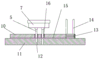
as shown in fig. 1, a punching device for a chain plate comprises a frame 1, wherein a motor is arranged above the frame 1, and the motor drives an eccentric wheel 6 to rotate to serve as a driving source. The eccentric wheel shaft is sleeved with a swing rod, the end part of the swing rod is provided with an upper plate 26, an installation plate 7 for installing a punch is fixed on the upper plate 26, and the punch 5 is installed on the installation plate 7. A mounting plate 24 for mounting the drive components of the feed mechanism is also secured to the upper plate 26.
The machine frame 1 is also provided with a workbench 2, the workbench 2 is fixed with an upper template 10 and a lower template 11, the upper template 10 is provided with two through holes 21, and the distance between the axes of the two through holes 21 is equal to the distance between the through holes on the chain plate 13 to be punched on the chain plate. A guide post 16 is installed in the through hole of the upper die plate 10, and a guide hole is formed on the guide post 16. The punch 5 moves up and down in the guide hole along with the rotation of the eccentric wheel, but the punch 5 is always positioned in the guide hole. A spray header 8 is arranged above the guide hole of the upper template 10. As shown in fig. 2, a scrap outlet 12 is provided in the lower die plate 11, the scrap outlet 12 communicates with the guide hole, and the scrap punched by the punch falls out of the scrap outlet. The bottom surface of the upper template 10 is provided with a chain plate channel 15, the chain plate channel 15 is a through groove arranged on the bottom surface, and the groove width is the same as the width of the chain plate 13 to be processed. A feed inlet 4 is formed in one end of the upper end face of the upper die plate 10, the shape of the feed inlet is the same as that of a chain plate to be processed, two baffle plates 14 are fixed in the feed inlet 4, and a cavity between the two baffle plates 14 is filled with the chain plate 13 to be processed. The other end of the upper template is connected with a discharge hole 9, and the processed chain plate falls into the receiving hopper.
As shown in fig. 3 and 4, a link plate positioning mechanism is disposed at a side surface of the upper die plate 10 where the guide posts are installed. The chain plate positioning mechanism comprises a positioning support 17, the positioning support 17 is U-shaped, and two support legs of the positioning support 17 are fixed on the side surface of the upper template 10. A through hole is arranged on the transverse connecting rod of the positioning bracket 17, a mandril 18 penetrates through the through hole, a compression spring 19 is sleeved on the mandril 18, one end of the mandril 18 is fixed on the transverse connecting rod of the positioning bracket 17, and the other end of the mandril 18 is abutted on a positioning plate 22. One end of the pressing spring 19 abuts against the positioning bracket 17, the other end of the pressing spring 19 abuts against the pressing plate 20, the pressing plate 20 is installed on the side surface of the upper die plate 10, and the pressing spring 19 is always in a compressed state. The positioning plate 22 is positioned in the upper template 10, one side of the positioning plate 22 is provided with an arc-shaped positioning surface, and the arc-shaped positioning surface has the same shape as the arc line of the side surface of the chain plate 13.
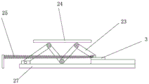
As shown in fig. 5 and 6, the feeding mechanism located at the rear side of the upper template 10 and the lower template 11 includes a push plate 3, the push plate 3 is U-shaped, one end of the push plate 3 is located in a chain plate channel 15 between the upper template and the lower template, and the other end of the push plate 3 is connected with a driving part. The driving part comprises a fixing plate 24, the fixing plate 24 is connected with the mounting plate 7 of the punch, a push-pull part 23 is arranged below the fixing plate 24, the push-pull part 23 is in an inverted W shape, one end of the push-pull part 23 is fixed on a bedplate 27 of the frame, the other end of the push-pull part 23 is connected with the push plate 3, two hinged points at the upper end of the push-pull part 23 are connected with the fixing plate, and a roller is arranged on a hinged shaft of a hinged point at the lower end of the push-pull part. One end of the push plate connected with the push-pull piece is provided with one end of a return spring 25, and the other end of the return spring is fixed on the rack. When the fixed plate 24 is lifted up, the push-pull piece 23 is pulled back by the return spring 25, and the push plate 3 is pulled to move forwards.
When the punching machine works, the motor drives the eccentric wheel to rotate, the eccentric shaft rotates to drive the fixing plate to move up and down, and therefore the punching head and the push-pull piece are driven to move up and down. The chain plates to be processed are sequentially placed into the chain plate storage mechanism between the two baffle plates, and the lowermost chain plate is directly positioned at the starting end of the chain plate channel. When the eccentric shaft moves, two hinged points of the push-pull part move downwards to press the push-pull part supporting rods which are hinged with each other to move, so that one end of the push plate is driven to move back and forth, the other end of the push plate, which is positioned in the chain plate channel, also moves along with the other end of the push plate, which is positioned below the chain plate storage mechanism, the thickness of the push plate is the same as that of the chain plates, when the push plate moves forwards, one of the chain plates is pushed forwards, when the push plate moves backwards, the push plate exits below the chain plate storage mechanism, the other chain plate falls into the starting end of the chain plate channel through gravity, then the push plate moves forwards again, the steps are repeated, one chain plate is pushed forwards, the distance from the starting end of the chain plate to the punching position of the chain plate is integral multiple of the length of the chain plate, therefore, after the repeated pushing, the foremost chain plate, the waste material flows out from the waste material outlet of the lower template, and the processed chain plate flows out from the discharge hole at the other end of the chain plate channel under the pushing of the back chain plate.
Claims (10)
1. The utility model provides a punching device of link joint, includes the frame, its characterized in that: the punching machine is characterized in that a workbench is arranged on the rack, a chain plate storage mechanism is arranged on the workbench, chain plates in the chain plate storage mechanism are conveyed to the lower side of the punching mechanism through a feeding mechanism, the punching mechanism comprises a punch, an upper template and a lower template, the upper template is positioned above the lower template, the punch is inserted into a guide hole in the upper template, a waste outlet is arranged below the lower template, and the punch is always positioned in the guide hole in the moving process.
2. The punching device of a link plate according to claim 1, wherein: the end surfaces of the upper template and the lower template are connected, a chain plate channel is formed in the lower bottom surface of the upper template, the chain plate storage mechanism is connected with the chain plate channel, the feeding mechanism comprises a push plate, the push plate is located at one end of the chain plate channel, and the other end of the chain plate channel is connected with a chain plate outlet.
3. The punching device of a link plate according to claim 1, wherein: the side of cope match-plate pattern be equipped with link joint positioning mechanism, link joint positioning mechanism include the locating support, the locating support is installed on the cope match-plate pattern, be equipped with the locating plate on the locating support, the locating plate is located the cope match-plate pattern, one side of locating plate is equipped with the arc locating surface, the arc locating surface is the same with the side arc line shape of link joint, the opposite side of locating plate is equipped with compresses tightly the piece.
4. The punching device of a link plate according to claim 3, wherein: the pressing piece comprises an ejector rod, one end of the ejector rod is connected with the side face of the positioning plate, a spring is sleeved on the ejector rod, one end of the spring abuts against the positioning support, the other end of the spring abuts against the pressing plate, the pressing plate is installed on the side face of the upper template, and the spring is always in a compressed state.
5. The punching apparatus of a link plate according to any one of claims 1 to 4, wherein: the feeding mechanism comprises a push plate, one end of the push plate is positioned in a chain plate channel between the upper template and the lower template, and the other end of the push plate is connected with a driving part.
6. The punching device of a link plate according to claim 5, wherein: the driving part comprises a fixed plate, the fixed plate is connected with the mounting plate of the punch, a push-pull piece is arranged below the fixed plate, the push-pull piece is inverted W-shaped, one end of the push-pull piece is fixed on the bedplate of the frame, the other end of the push-pull piece is connected with a push plate, two hinged points at the upper end of the push-pull piece are connected with the fixed plate, and a roller is arranged on a hinged shaft of a hinged point at the lower end of the push-pull piece.
7. The punching apparatus of a link plate according to any one of claims 1 to 4, wherein: the chain plate storage mechanism is composed of two baffle plates, the shape between the two baffle plates is the same as that of the chain plate, a feed inlet in the same shape as that of the chain plate is formed in the upper template, and the end parts of the two baffle plates are fixed in the feed inlet.
8. The punching apparatus of a link plate according to any one of claims 1 to 4, wherein: the forming mechanism that cope match-plate pattern, lower bolster and drift formed be located the workstation front side, feed mechanism is located the workstation rear side, forming mechanism is parallel to each other with feed mechanism, feed mechanism includes the push pedal, the push pedal is the U-shaped, the one end of push pedal links to each other with the driver part in the feed mechanism, the other end of push pedal is located the link joint passageway between cope match-plate pattern and the lower bolster, promotes the link joint and advances.
9. The punching apparatus of a link plate according to any one of claims 1 to 4, wherein: the machine frame is provided with an eccentric wheel serving as a driving source of the punch, a swing rod is sleeved on an eccentric wheel shaft, an upper plate is arranged at the end part of the swing rod, a mounting plate for mounting the punch is fixed on the upper plate, and a fixing plate for mounting a driving part of the feeding mechanism is fixed on the upper plate.
10. The punching apparatus of a link plate according to any one of claims 1 to 4, wherein: and a spray header is arranged above the guide hole of the upper template.
Priority Applications (1)
| Application Number | Priority Date | Filing Date | Title |
|---|---|---|---|
| CN201921637350.3U CN210907633U (en) | 2019-09-29 | 2019-09-29 | Punching device of chain plate |
Applications Claiming Priority (1)
| Application Number | Priority Date | Filing Date | Title |
|---|---|---|---|
| CN201921637350.3U CN210907633U (en) | 2019-09-29 | 2019-09-29 | Punching device of chain plate |
Publications (1)
| Publication Number | Publication Date |
|---|---|
| CN210907633U true CN210907633U (en) | 2020-07-03 |
Family
ID=71354539
Family Applications (1)
| Application Number | Title | Priority Date | Filing Date |
|---|---|---|---|
| CN201921637350.3U Active CN210907633U (en) | 2019-09-29 | 2019-09-29 | Punching device of chain plate |
Country Status (1)
| Country | Link |
|---|---|
| CN (1) | CN210907633U (en) |
Cited By (1)
| Publication number | Priority date | Publication date | Assignee | Title |
|---|---|---|---|---|
| CN110624996A (en) * | 2019-09-29 | 2019-12-31 | 杭州萧山万隆链条制造有限公司 | Punching device of chain plate |
-
2019
- 2019-09-29 CN CN201921637350.3U patent/CN210907633U/en active Active
Cited By (1)
| Publication number | Priority date | Publication date | Assignee | Title |
|---|---|---|---|---|
| CN110624996A (en) * | 2019-09-29 | 2019-12-31 | 杭州萧山万隆链条制造有限公司 | Punching device of chain plate |
Similar Documents
| Publication | Publication Date | Title |
|---|---|---|
| CN111390008A (en) | Metal gasket stamping device for machining | |
| CN113263094A (en) | Metal stamping forming device | |
| CN220295638U (en) | Punch press of waste material clearance of being convenient for | |
| CN210907633U (en) | Punching device of chain plate | |
| CN212682340U (en) | Automatic stamping and bending equipment of material loading | |
| CN110624996A (en) | Punching device of chain plate | |
| CN210816933U (en) | Positioning structure of chain plate punching device | |
| CN111360287A (en) | Full-automatic positioning and punching device and working method thereof | |
| CN215392066U (en) | Continuous stamping die is used in seat processing | |
| CN214517131U (en) | Stamping die is used in forging processing | |
| CN213530339U (en) | Die punching machine | |
| CN210045909U (en) | Steel wire rope and rivet riveting and steel wire rope cutting mechanism | |
| CN211990668U (en) | Punch forming device | |
| CN213559369U (en) | Stamping device for automobile fastener | |
| CN209736419U (en) | Stamping die for processing lug plate | |
| CN210280554U (en) | Hinge riveting machine | |
| CN210754566U (en) | Plate stamping device | |
| CN113198904A (en) | Automobile steering knuckle casting punching device without tool withdrawal resistance and punching method thereof | |
| CN110711815A (en) | Punching positioning mechanism for machining fastener | |
| CN214601265U (en) | Punching machine with scoring function | |
| CN212976880U (en) | Waste material cutting device of punching machine | |
| CN219402187U (en) | Automatic change link joint and compound hole equipment | |
| CN220992644U (en) | Bearing retainer ring stamping device | |
| CN221109679U (en) | Automatic blade punching machine of ejection of compact | |
| CN213224019U (en) | Pipe flaring and punching machine |
Legal Events
| Date | Code | Title | Description |
|---|---|---|---|
| GR01 | Patent grant | ||
| GR01 | Patent grant |