CN210887272U - Assembled steel mould for foundation bearing platform of house building engineering - Google Patents
Assembled steel mould for foundation bearing platform of house building engineering Download PDFInfo
- Publication number
- CN210887272U CN210887272U CN201921700343.3U CN201921700343U CN210887272U CN 210887272 U CN210887272 U CN 210887272U CN 201921700343 U CN201921700343 U CN 201921700343U CN 210887272 U CN210887272 U CN 210887272U
- Authority
- CN
- China
- Prior art keywords
- steel mould
- rods
- left end
- diaphragm
- square frame
- Prior art date
- Legal status (The legal status is an assumption and is not a legal conclusion. Google has not performed a legal analysis and makes no representation as to the accuracy of the status listed.)
- Expired - Fee Related
Links
Images


Abstract
The utility model discloses an assembled steel mould for house building engineering basis cushion cap, including the steel mould, the right-hand member processing of steel mould is fluted, the outer wall of rack and the left end clearance fit of recess, the front processing of pole has the hexagonal hole, the inside of square frame is equipped with the screens subassembly, the bottom of diaphragm is equipped with adjusting part. This an assembled steel mould for house building engineering basis cushion cap, through the recess, the cooperation of screens subassembly and draw-in groove, make two steel moulds can aim at fast and splice when the installation, through the gear, the cooperation of rack and hexagonal hole, make two steel moulds can realize the quickly separating dismantlement, and then realize quick assembly disassembly, promote dismouting efficiency, shorten the engineering cycle, and the greatly reduced dismouting degree of difficulty, through adjusting part, the cooperation of diaphragm and steel mould, make the bearing area of diaphragm can adjust according to the use needs, and then enlarge application scope, promote practicality and stability.
Description
Technical Field
The utility model relates to an assembled steel mould technical field for house building engineering basis cushion cap specifically is an assembled steel mould for house building engineering basis cushion cap.
Background
The building steel mould belongs to one of steel mould, and the classification is often carried out by the usage of steel mould, and common classification has: high-speed railway roof beam body steel form, high-speed railway pier stud steel form, highway bridge template, harbour worker shipping steel form, water conservancy water and electricity steel form and building steel mould, the assembled steel mould that is used for house building engineering basis cushion cap among the prior art, can't realize aim at fast and the concatenation when two steel mould installations, and can't realize the quickly separating dismantlement, and then can't realize quick assembly disassembly, reduce dismouting efficiency, increase engineering cycle, and the greatly increased dismouting degree of difficulty, and bearing area can not adjust according to the use needs, and then reduce application scope, reduce practicality and stability, inconvenient people use.
SUMMERY OF THE UTILITY MODEL
An object of the utility model is to provide an assembled steel mould for house building engineering basis cushion cap, an assembled steel mould for house building engineering basis cushion cap among the prior art is proposed in solving above-mentioned background art, can't realize aiming at fast and the concatenation when two steel mould installations, and can't realize the quickly separating dismantlement, and then can't realize quick assembly disassembly, reduce dismouting efficiency, increase engineering cycle, and the greatly increased dismouting degree of difficulty, and bearing area can not adjust according to the use needs, and then reduce application scope, reduce practicality and stability, the problem of inconvenient people's use.
In order to achieve the above object, the utility model provides a following technical scheme: the utility model provides an assembled steel mould for house building engineering basis cushion cap, includes the steel mould, the right-hand member processing of steel mould is fluted, the equal rigid coupling in upper and lower both ends of recess has the draw-in groove, the internal rotation of recess is connected with the round bar, the outer wall rigid coupling of round bar has the gear, the top meshing of gear is connected with the rack, the outer wall of rack and the left end clearance fit of recess, the positive processing of round bar has the hexagonal hole, the left end rigid coupling of steel mould has the square frame, the inside of square frame is equipped with the screens subassembly, the positive top rigid coupling of steel mould has the diaphragm, the bottom of diaphragm is equipped with adjusting part.
Preferably, the groove is arranged corresponding to the square frame.
Preferably, the screens subassembly includes branch, montant, fixture block, down tube, extension board, horizontal pole, spout and spring, two the left end of branch all with the inner wall left end rigid coupling of square frame together, the equal clearance fit in inside of branch has the montant, the outer end rigid coupling of montant has the fixture block, the outer wall of fixture block and the upper and lower both ends clearance fit of square frame, the inner of montant all rotates and is connected with the down tube, the inner of down tube all rotates and is connected with the extension board, the right-hand member rigid coupling of extension board has the horizontal pole, the outer wall of horizontal pole passes through the left end clearance fit of spout and steel mould, the spring has been cup jointed to the outer wall of horizontal pole, both ends are fixed continuous with extension board and steel mould respectively about the spring.
Preferably, the axis of the cross bar coincides with the axis of the square frame.
Preferably, the adjusting part includes roof, riser, bolt and bearing, the right-hand member of roof and the left end clearance fit of diaphragm, the bottom rigid coupling of roof has the riser, the inside below bolted connection of riser has the bolt, the right-hand member of bolt passes through the bearing and rotates with the left end below of diaphragm and links to each other.
Preferably, the top plate and the transverse plate form a sliding structure.
Compared with the prior art, the beneficial effects of the utility model are that: this an assembled steel mould for house building engineering basis cushion cap, through the recess, the cooperation of screens subassembly and draw-in groove, make two steel moulds can aim at fast and splice when the installation, through the gear, the cooperation of rack and hexagonal hole, make two steel moulds can realize the quickly separating dismantlement, and then realize quick assembly disassembly, promote dismouting efficiency, shorten the engineering cycle, and the greatly reduced dismouting degree of difficulty, through adjusting part, the cooperation of diaphragm and steel mould, make the bearing area of diaphragm can adjust according to the use needs, and then enlarge application scope, promote practicality and stability, make things convenient for people to use.
Drawings
FIG. 1 is a schematic structural view of the present invention;
FIG. 2 is a schematic diagram of a right-view partial connection of FIG. 1;
FIG. 3 is a schematic view showing the connection relationship between the square frame, the sliding groove and the vertical rod in FIG. 1;
fig. 4 is a schematic view showing the connection relationship between the groove, the steel die and the gear in fig. 1.
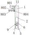
In the figure: 1. the steel mould, 2, recess, 3, draw-in groove, 4, round bar, 5, gear, 6, rack, 7, screens subassembly, 701, branch, 702, montant, 703, fixture block, 704, down tube, 705, extension board, 706, horizontal pole, 707, spout, 708, spring, 8, adjusting part, 801, roof, 802, riser, 803, bolt, 804, bearing, 9, hexagonal hole, 10, square frame, 11, diaphragm.
Detailed Description
The technical solutions in the embodiments of the present invention will be described clearly and completely with reference to the accompanying drawings in the embodiments of the present invention, and it is obvious that the described embodiments are only some embodiments of the present invention, not all embodiments. Based on the embodiments in the present invention, all other embodiments obtained by a person skilled in the art without creative work belong to the protection scope of the present invention.
Referring to fig. 1-4, the present invention provides a technical solution: an assembled steel mould for a foundation bearing platform of house building engineering comprises a steel mould 1, a groove 2 is processed at the right end of the steel mould 1, clamping grooves 3 are fixedly connected to the upper end and the lower end of the groove 2, the clamping grooves 3 are symmetrically distributed about the axis of the groove 2, a round rod 4 is rotatably connected inside the groove 2, a gear 5 is fixedly connected to the outer wall of the round rod 4, the gear 5 can rotate when being stressed due to the round rod 4, a rack 6 is meshed and connected to the top of the gear 5, the outer wall of the rack 6 is in clearance fit with the left end of the groove 2, the groove 2 plays a guiding role on the rack 6, a hexagonal hole 9 is processed on the front side of the round rod 4, the hexagonal hole 9 is used for rotating the round rod 4, a square frame 10 is fixedly connected to the left end of the steel mould 1, the groove 2 corresponds to the square frame 10, the square frame 10 can be inserted into the groove 2, a clamping component 7 is arranged inside the square frame 10, a transverse plate 11 is fixedly connected to the front top, the bottom of diaphragm 11 is equipped with adjusting part 8.
The clamping component 7 comprises supporting rods 701, vertical rods 702, clamping blocks 703, inclined rods 704, supporting plates 705, cross rods 706, sliding grooves 707 and springs 708, the left ends of the two supporting rods 701 are fixedly connected with the left end of the inner wall of the square frame 10, the supporting rods 701 are symmetrically distributed around the axis of the square frame 10, the vertical rods 702 are in clearance fit in the supporting rods 701, the supporting rods 701 play a guiding role for the vertical rods 702, the clamping blocks 703 are fixedly connected with the outer ends of the vertical rods 702, the clamping blocks 703 and the clamping grooves 3 can be clamped when the square frame 10 is inserted into the grooves 2, the outer walls of the clamping blocks 703 are in clearance fit with the upper end and the lower end of the square frame 10, the inner ends of the vertical rods 702 are rotatably connected with the inclined rods 704, the inner ends of the inclined rods 704 are rotatably connected with the supporting plates, the inclined rods 704 are symmetrically distributed around the axis of the supporting plates 705, the right ends of the supporting plates 705 are fixedly connected with the cross rods 706, the axis, the outer wall of the cross rod 706 is in clearance fit with the left end of the steel die 1 through the sliding groove 707, the spring 708 is sleeved on the outer wall of the cross rod 706, the spring 708 provides limiting force for the cross rod 706, the inner end of the inclined plane of the clamping block 704 is flush with the outer wall of the square frame 10 when the clamping block is not stressed, and the left end and the right end of the spring 708 are fixedly connected with the support plate 705 and the steel die 1 respectively.
Adjusting part 8 includes roof 801, riser 802, bolt 803 and bearing 804, the right-hand member of roof 801 and the left end clearance fit of diaphragm 11, roof 801 and diaphragm 11 constitute sliding construction, diaphragm 11 plays the guide effect to roof 801, the bottom rigid coupling of roof 801 has riser 802, the inside below bolted connection of riser 802 has bolt 803, can drive roof 801 side-to-side movement when bolt 803 is twisted, the right-hand member of bolt 803 passes through bearing 804 and rotates the link to each other with the left end below of diaphragm 11, but bearing 804 makes bolt 803 free rotation when the atress.
In this embodiment, when the assembly type steel form for the foundation bearing platform of the building construction engineering is used, the square frame 10 can be inserted into the groove 2 by the corresponding arrangement of the square frame 10 and the groove 2, when the fixture block 703 is in contact with the inner wall of the groove 2, the fixture block 703 can move inwards by overcoming the elastic force of the spring 708 through the inclined surface at the left end of the fixture block 703 and the clearance fit of the support rod 701 and the vertical rod 702, so that the cross rod 706 slides to the right side of the chute 707, when the fixture block 703 moves to the position of the clamping groove 3, the spring 708 gives a leftward force to the support plate 705, so that the fixture block 703 returns to the initial position, and the clamping groove 3 is clamped and connected, so that the splicing speed of the two steel forms 1 is higher, the installation difficulty is reduced, the round rod 4 is rotatably connected with the groove 2, and the round rod 4 can be rotated clockwise by the action of the hexagonal hole 9, and is connected with the rack, make rack 6 move to the right, and then rack 6 gives the right power of extension board 705, make fixture block 703 shrink inwards, and then to the separation of draw-in groove 3 joint, make two steel mould 1 quick separation dismantlements, and then realize quick assembly disassembly, through rotating bolt 803, it is continuous with riser 802 screw thread through bolt 803 to and bolt 803 links to each other with the rotation of diaphragm 11, make roof 801 side to side motion, and then enlarge the bearing area of diaphragm 11, and then make things convenient for people to use.
In the description of the present invention, it is to be understood that the terms "coaxial", "bottom", "one end", "top", "middle", "other end", "upper", "one side", "top", "inner", "front", "center", "both ends", and the like, indicate orientations or positional relationships based on the orientations or positional relationships shown in the drawings, and are only for convenience of description and simplicity of description, and do not indicate or imply that the device or element referred to must have a particular orientation, be constructed and operated in a particular orientation, and therefore, should not be construed as limiting the present invention.
In the present invention, unless otherwise expressly stated or limited, the terms "mounted," "disposed," "connected," "fixed," "screwed" and the like are to be construed broadly, e.g., as meaning fixedly connected, detachably connected, or integrally formed; can be mechanically or electrically connected; they may be directly connected or indirectly connected through an intermediate medium, and may be connected through the inside of two elements or in an interaction relationship between two elements, unless otherwise specifically defined, and the specific meaning of the above terms in the present invention will be understood by those skilled in the art according to specific situations.
Although embodiments of the present invention have been shown and described, it will be appreciated by those skilled in the art that changes, modifications, substitutions and alterations can be made in these embodiments without departing from the principles and spirit of the invention, the scope of which is defined in the appended claims and their equivalents.
Claims (6)
1. The utility model provides an assembled steel mould for house building engineering basis cushion cap, includes steel mould (1), its characterized in that: the right-hand member of steel mould (1) is processed there are recess (2), the equal rigid coupling in upper and lower both ends of recess (2) has draw-in groove (3), the internal rotation of recess (2) is connected with round bar (4), the outer wall rigid coupling of round bar (4) has gear (5), the top meshing of gear (5) is connected with rack (6), the outer wall of rack (6) and the left end clearance fit of recess (2), the positive processing of round bar (4) has hexagonal hole (9), the left end rigid coupling of steel mould (1) has square frame (10), the inside of square frame (10) is equipped with screens subassembly (7), the positive top rigid coupling of steel mould (1) has diaphragm (11), the bottom of diaphragm (11) is equipped with adjusting part (8).
2. The fabricated steel form for a foundation cap of housing construction work according to claim 1, wherein: the groove (2) is arranged corresponding to the square frame (10).
3. The fabricated steel form for a foundation cap of housing construction work according to claim 1, wherein: the clamping component (7) comprises supporting rods (701), vertical rods (702), clamping blocks (703), inclined rods (704), supporting plates (705), transverse rods (706), sliding grooves (707) and springs (708), the left ends of the two supporting rods (701) are fixedly connected with the left end of the inner wall of the square frame (10), the vertical rods (702) are uniformly in clearance fit in the supporting rods (701), the clamping blocks (703) are fixedly connected with the outer ends of the vertical rods (702), the outer walls of the clamping blocks (703) are in clearance fit with the upper end and the lower end of the square frame (10), the inner ends of the vertical rods (702) are rotatably connected with the inclined rods (704), the inner ends of the inclined rods (704) are rotatably connected with the supporting plates (705), the right ends of the supporting plates (705) are fixedly connected with the transverse rods (706), the outer walls of the transverse rods (706) are in clearance fit with the left end of the steel die (1) through the sliding grooves (707), and the springs (708) are sleeved on, the left end and the right end of the spring (708) are respectively fixedly connected with the support plate (705) and the steel die (1).
4. The fabricated steel form for a foundation cap of housing construction work according to claim 3, wherein: the axis of the cross rod (706) is coincident with the axis of the square frame (10).
5. The fabricated steel form for a foundation cap of housing construction work according to claim 1, wherein: adjusting part (8) include roof (801), riser (802), bolt (803) and bearing (804), the right-hand member of roof (801) and the left end clearance fit of diaphragm (11), the bottom rigid coupling of roof (801) has riser (802), the inside below bolted connection of riser (802) has bolt (803), the right-hand member of bolt (803) passes through bearing (804) and rotates continuously with the left end below of diaphragm (11).
6. The fabricated steel form for a foundation cap of housing construction work according to claim 5, wherein: the top plate (801) and the transverse plate (11) form a sliding structure.
Priority Applications (1)
| Application Number | Priority Date | Filing Date | Title |
|---|---|---|---|
| CN201921700343.3U CN210887272U (en) | 2019-10-12 | 2019-10-12 | Assembled steel mould for foundation bearing platform of house building engineering |
Applications Claiming Priority (1)
| Application Number | Priority Date | Filing Date | Title |
|---|---|---|---|
| CN201921700343.3U CN210887272U (en) | 2019-10-12 | 2019-10-12 | Assembled steel mould for foundation bearing platform of house building engineering |
Publications (1)
| Publication Number | Publication Date |
|---|---|
| CN210887272U true CN210887272U (en) | 2020-06-30 |
Family
ID=71324183
Family Applications (1)
| Application Number | Title | Priority Date | Filing Date |
|---|---|---|---|
| CN201921700343.3U Expired - Fee Related CN210887272U (en) | 2019-10-12 | 2019-10-12 | Assembled steel mould for foundation bearing platform of house building engineering |
Country Status (1)
| Country | Link |
|---|---|
| CN (1) | CN210887272U (en) |
Cited By (1)
| Publication number | Priority date | Publication date | Assignee | Title |
|---|---|---|---|---|
| CN113482320A (en) * | 2021-07-21 | 2021-10-08 | 曹成朋 | Assembled building templates |
-
2019
- 2019-10-12 CN CN201921700343.3U patent/CN210887272U/en not_active Expired - Fee Related
Cited By (1)
| Publication number | Priority date | Publication date | Assignee | Title |
|---|---|---|---|---|
| CN113482320A (en) * | 2021-07-21 | 2021-10-08 | 曹成朋 | Assembled building templates |
Similar Documents
| Publication | Publication Date | Title |
|---|---|---|
| CN210887272U (en) | Assembled steel mould for foundation bearing platform of house building engineering | |
| CN210510117U (en) | Buffer gear for electromechanical device maintenance | |
| CN211057837U (en) | Assembled steel mould for foundation bearing platform of house building engineering | |
| CN210942883U (en) | Solar glass plate placing device with good fixing effect | |
| CN110670797B (en) | Assembled concrete prefabricated plate | |
| CN201772229U (en) | Wall hung TV movable frame | |
| CN209800450U (en) | Portable steel support convenient to concatenation is built | |
| CN212783656U (en) | Battery bottom plate for new energy automobile battery pack | |
| CN210949415U (en) | Splicing structure of aluminum profiles | |
| CN209190246U (en) | A kind of mold hard rail of machining center | |
| CN211312577U (en) | Pile cap steel formwork | |
| CN213329667U (en) | Adjustable steel supporting beam structure for construction of waste incineration pool | |
| CN208533710U (en) | A kind of novel fabricated steel structure node | |
| CN209394188U (en) | A kind of welding equipment for aluminum alloy mould plate processing | |
| CN212292935U (en) | Acidic oxidation potential water generating device | |
| CN215166949U (en) | Adjustable curtain connecting piece of assembled building | |
| CN215848244U (en) | Manipulator clamping structure | |
| CN212251927U (en) | Scalable solar energy control pole of control angularly adjustable | |
| CN213391223U (en) | Building templates link for civil engineering | |
| CN214399702U (en) | Safety guarantee equipment for electric power operation site | |
| CN209799017U (en) | Connection structure of light gauge steel | |
| CN211571386U (en) | Guardrail is used in bridge construction | |
| CN216565343U (en) | High definition industry camera position adjustment structure | |
| CN219750103U (en) | Course push rod limiting assembly for ship | |
| CN219881575U (en) | Fiber laser pipe cutting machine with supporting structure |
Legal Events
| Date | Code | Title | Description |
|---|---|---|---|
| GR01 | Patent grant | ||
| GR01 | Patent grant | ||
| CF01 | Termination of patent right due to non-payment of annual fee |
Granted publication date: 20200630 Termination date: 20211012 |
|
| CF01 | Termination of patent right due to non-payment of annual fee |