CN210857992U - A consolidate bearing structure for building engineering - Google Patents
A consolidate bearing structure for building engineering Download PDFInfo
- Publication number
- CN210857992U CN210857992U CN201921562390.6U CN201921562390U CN210857992U CN 210857992 U CN210857992 U CN 210857992U CN 201921562390 U CN201921562390 U CN 201921562390U CN 210857992 U CN210857992 U CN 210857992U
- Authority
- CN
- China
- Prior art keywords
- fixed
- buffer
- plate
- block
- column
- Prior art date
- Legal status (The legal status is an assumption and is not a legal conclusion. Google has not performed a legal analysis and makes no representation as to the accuracy of the status listed.)
- Active
Links
Images



Landscapes
- Buildings Adapted To Withstand Abnormal External Influences (AREA)
Abstract
The utility model discloses a consolidate bearing structure for building engineering, include: the buffer structure comprises a sleeve, a support column, a buffer block and a bottom plate, wherein a convex cavity is arranged in the buffer block, the lower end of the support column is arranged in the buffer block and is connected with a buffer plate, a connecting column is fixed in the middle of the bottom surface of the buffer plate, a corrugated rubber pad is embedded and connected on the connecting column, and the bottom of the corrugated rubber pad is fixedly connected with the bottom plate; the support column surface is provided with helicitic texture one, and the support column surface just is located the vertical recess of seting up in the middle part of helicitic texture one, and the equal bottom in support column both sides all is provided with the fixed block, and the fixed block middle part is inlayed and is connected with the regulation pole. The supporting column of the utility model is connected with the corrugated rubber pad and the spring inside the buffer block, has certain damping and buffering capacity, and increases the anti-seismic performance of the supporting structure; the support column surface is seted up the recess, inlays the fixture block through rotating the regulation pole and is connected with the recess, can take place pivoted phenomenon in the use sleeve pipe of support on the surface, guarantees its normal use.
Description
Technical Field
The utility model relates to a building engineering technical field, more specifically are a reinforced support structure for building engineering.
Background
As the existing house buildings all require to reach a certain quakeproof level, the common buildings all adopt cast-in-place floors and shear wall structures, so that the building template supporting structure is widely applied, the national wood is increasingly poor, the forest cutting is limited in the south and north China, and the steel building template support will become a trend of the future cast-in-place concrete supporting frame. Chinese patent document CN209082985U discloses a reinforced support structure for building engineering, which includes a bottom plate, a support column is vertically and fixedly connected to the middle position of the top of the bottom plate, two thirds of the upper portion of the support column is provided with fastening threads, the support column is sleeved with a support sleeve, and the lower portions of the left and right sides of the support sleeve are horizontally and fixedly connected with a splicing pipe.
Above-mentioned a consolidate bearing structure for building engineering, though can realize the activity and go up and down and reach simple support, this bearing structure's shock resistance is relatively poor, does not possess the absorbing effect of buffering when supporting, and it carries out altitude mixture control through the screw thread, can produce certain vibrations in the construction, and the screw thread easily slides and makes the sleeve pipe move down, influences its supporting effect.
SUMMERY OF THE UTILITY MODEL
An object of the utility model is to provide a consolidate bearing structure for building engineering has solved the problem that proposes in the background art, satisfies the in-service use demand.
In order to achieve the above object, the utility model provides a following technical scheme: a reinforced support structure for construction work, comprising: the buffer structure comprises a sleeve, a support column, a buffer block and a bottom plate, wherein a convex cavity is arranged in the buffer block, the lower end of the support column is arranged in the buffer block and is connected with a buffer plate, a connecting column is fixed in the middle of the bottom surface of the buffer plate, a corrugated rubber pad is embedded and connected on the connecting column, and the bottom of the corrugated rubber pad is fixedly connected with the bottom plate; the utility model discloses a support post, including support post, fixed block, regulation pole, handle, fixture block and recess, the support post surface is provided with helicitic texture one, the vertical recess of seting up in the middle part that just is located helicitic texture one on support post surface, the equal bottom in support post both sides all is provided with the fixed block, the fixed block middle part is inlayed and is connected with the regulation pole, it is provided with the fixture block to adjust pole one.
As an optimal implementation mode of the utility model, spread groove and kerve have been seted up in the ripple rubber pad, the spacing groove has still been seted up on the spread groove inner wall, the spliced pole activity sets up in the spread groove and the spliced pole outer wall is fixed with the limiting plate, the limiting plate is inlayed and is connected in the spacing groove.
As an optimal implementation mode of the utility model, be provided with connecting plate and spring two in the kerve, the connecting plate is fixed in two upper ends of spring, the vertical a plurality of buffering branch that is fixed with in the column bottom, buffering branch lower extreme extend to the kerve in and with connecting plate fixed connection.
As an optimal implementation mode, the symmetry is provided with the regulating plate on the support column, the buffer block is fixed at bottom plate top surface middle part, and the bottom plate top surface is located the vertical telescopic link that is fixed with in buffer block both sides, telescopic link upper end and regulating plate fixed connection, inside still symmetry of buffer block and vertical buffer column of being fixed with, buffer column and buffer board swing joint, the buffer column surface just is located the buffer board below and has cup jointed spring one.
As the utility model discloses a preferred embodiment, set up on the fixed block and inlayed the hole, it is downthehole that regulation pole swing joint inlays, the fixed orifices has been seted up to the sleeve pipe lower extreme, the fixed orifices with inlay the vertical nut that is fixed with in hole intercommunication and the fixed orifices, be provided with helicitic texture two on the regulation pole.
As an optimal implementation mode of the utility model, set up the internal thread on the cover intraductal wall, sleeve pipe upper end still is connected with the roof, the inside hollow structure and the installation bearing that is of roof, sleeve pipe upper end is fixed with the regulation post and rotates with the bearing through adjusting the post and be connected.
Compared with the prior art, the beneficial effects of the utility model are as follows:
(1) this bearing structure has set up the buffer block in the bottom, and the support column has certain shock attenuation buffer capacity with inside ripple rubber pad and the spring coupling of buffer block, increases bearing structure's anti-seismic performance.
(2) This bearing structure, the recess is seted up on the support column surface, inlays fixture block and recess through rotating the regulation pole and is connected, and the pivoted phenomenon takes place for the sleeve pipe in the use that can the surface support, guarantees its normal use.
Drawings
Fig. 1 is a front view of a reinforced support structure for construction work according to the present invention;
fig. 2 is a cross-sectional view of the reinforced support structure for construction engineering of the present invention;
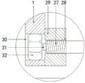
FIG. 3 is an enlarged view of A in FIG. 1;
fig. 4 is an enlarged view of B in fig. 1.
In the figure, a sleeve 1; a top plate 2; an adjusting rod 3; a support column 4; a bottom plate 5; a buffer block 6; a telescopic rod 7; an adjusting plate 8; an adjusting column 9; a bearing 10; an internal thread 11; a first thread structure 12; a groove 13; a handle 14; a buffer column 15; a buffer plate 16; a first spring 17; a corrugated rubber mat 18; a connecting column 19; a position limiting plate 20; a limit groove 21; a connecting groove 22; a buffer strut 23; a bottom groove 24; a second spring 25; a connecting plate 26; a second thread structure 27; a mosaic hole 28; a fixed block 29; a fixing hole 30; a latch 31; a nut 32.
Detailed Description
The technical solutions in the embodiments of the present invention will be described clearly and completely with reference to the accompanying drawings in the embodiments of the present invention, and it is obvious that the described embodiments are only some embodiments of the present invention, not all embodiments. Based on the embodiments in the present invention, all other embodiments obtained by a person skilled in the art without creative work belong to the protection scope of the present invention.
Referring to fig. 1-4, the present invention provides a technical solution: a reinforced support structure for construction work, comprising: the damping device comprises a sleeve 1, a supporting column 4, a buffer block 6 and a bottom plate 5, wherein a convex cavity is arranged inside the buffer block 6, the lower end of the supporting column 4 is arranged in the buffer block 6 and is connected with a buffer plate 16, a connecting column 19 is fixed in the middle of the bottom surface of the buffer plate 16, a corrugated rubber pad 18 is embedded and connected onto the connecting column 19, the bottom of the corrugated rubber pad 18 is fixedly connected with the bottom plate 5, and the damping and the buffering are carried out through a spring inside the buffer block 6 and the corrugated rubber pad 18; 4 surfaces of support column are provided with screw-thread structure 12, 4 surfaces of support column and the vertical recess 13 of seting up in middle part that is located screw-thread structure 12, 4 both sides of support column all bottom is provided with fixed block 29, fixed block 29 middle part is inlayed and is connected with regulation pole 3, 3 one end of regulation pole are provided with fixture block 31, the handle 14 has been cup jointed to the other end, fixture block 31 is inlayed with recess 13 and is connected, inlay when recess 13 when fixture block 31, support column 4 can't rotate, can also set up the scale in the recess 13, the height is looked over in the convenience.
Further improved, as shown in fig. 2: connecting groove 22 and kerve 24 have been seted up in corrugated rubber pad 18, spacing groove 21 has still been seted up on the connecting groove 22 inner wall, and the activity of spliced pole 19 sets up in connecting groove 22 and the outer wall of spliced pole 19 is fixed with limiting plate 20, and limiting plate 20 inlays the connection in spacing groove 21, plays limiting displacement, has also played the effect of dispersed pressure simultaneously.
Further improved, as shown in fig. 4: be provided with connecting plate 26 and second spring 25 in the kerve 24, connecting plate 26 is fixed in second spring 25 upper end, and the vertical a plurality of buffering branch 23 that is fixed with in spliced pole 19 bottom, buffering branch 23 lower extreme extend to the kerve 24 in and with connecting plate 26 fixed connection, seted up the through-hole of inlaying buffering branch in the ripple rubber pad, buffering branch 23 has played the effect of dispersion vibrations.
Further improved, as shown in fig. 2: the symmetry is provided with regulating plate 8 on support column 4, buffer block 6 is fixed at 5 top surfaces of bottom plate middle part, and 5 top surfaces of bottom plate are located the vertical telescopic link 7 that is fixed with in 6 both sides of buffer block, 7 upper ends of telescopic link and 8 fixed connection of regulating plate, the inside symmetry and the vertical buffer column 15 that are fixed with of buffer block 6, buffer column 15 and buffer plate 16 swing joint, buffer column 15 surface just is located buffer plate 16 below cover and has connect spring 17, telescopic link 7 and 8 cooperation use of regulating plate can play certain limiting displacement to support column 15, buffer column 15 dish cooperation spring 17 uses and plays absorbing effect.
In a further improvement, as shown in fig. 3: seted up on fixed block 29 and inlayed hole 28, adjust pole 3 swing joint in inlaying hole 28, the fixed orifices 30 have been seted up to sleeve pipe 1 lower extreme, fixed orifices 30 with inlay in hole 28 intercommunication and the fixed orifices 30 vertical nut 32 that is fixed with, be provided with two 27 of helicitic texture on adjusting pole 3, when adjusting 3 cooperation nuts 32 uses of pole, adjust pole 3 and carry out horizontal displacement when rotating and adjusting pole 3, it is convenient to adjust.
Specifically, internal thread 11 has been seted up on the sleeve pipe 1 inner wall, and sleeve pipe 1 upper end still is connected with roof 2, and roof 2 is inside to be hollow structure and to install bearing 10, and sleeve pipe 1 upper end is fixed with adjusts post 9 and rotates with bearing 10 through adjusting post 9 to be connected, and bearing connecting sleeve 1 makes sleeve pipe 1 rotate steadily.
The utility model discloses when using, place the place that needs the installation in bearing structure, then will adjust pole 3 and insert and inlay in hole 28, then promote and adjust pole 3, make sleeve pipe 1 rotate, sleeve pipe 1 is through internal thread effect rebound in the pivoted, make after the installation is accomplished and inlay hole 28 and recess 13 to it, then rotate and adjust pole 3, make fixture block 31 inlay in recess 13, can avoid sleeve pipe 1 to take place the mistake and change, come to disperse the buffering to vibrations through spring and ripple rubber pad 18 in the buffer block 6, reduce the damage that vibrations caused bearing structure.
The product protected by the scheme is put into practical production and application at present, and particularly achieves certain success in the application field of building engineering, so that the technical scheme of the product is obviously proved to be beneficial, meets social requirements, and is suitable for batch production and popularization and use.
Finally, it should be noted that: although the present invention has been described in detail with reference to the foregoing embodiments, it will be apparent to those skilled in the art that modifications may be made to the embodiments described in the foregoing embodiments, or equivalents may be substituted for elements thereof. Any modification, equivalent replacement, or improvement made within the spirit and principle of the present invention should be included in the protection scope of the present invention.
Claims (6)
1. A reinforced support structure for construction work, comprising: sleeve pipe (1), support column (4), buffer block (6) and bottom plate (5), its characterized in that: a convex cavity is arranged in the buffer block (6), the lower end of the supporting column (4) is arranged in the buffer block (6) and is connected with a buffer plate (16), a connecting column (19) is fixed in the middle of the bottom surface of the buffer plate (16), a corrugated rubber pad (18) is embedded and connected on the connecting column (19), and the bottom of the corrugated rubber pad (18) is fixedly connected with the bottom plate (5);
support column (4) surface is provided with helicitic texture (12), support column (4) surface just is located the vertical recess (13) of seting up in middle part of helicitic texture (12), the equal bottom in support column (4) both sides all is provided with fixed block (29), fixed block (29) middle part is inlayed and is connected with regulation pole (3), it is provided with fixture block (31) to adjust pole (3) one end, the other end has cup jointed handle (14), fixture block (31) are inlayed with recess (13) and are connected.
2. A reinforced support structure for construction work according to claim 1, wherein: seted up spread groove (22) and kerve (24) in ripple rubber pad (18), spacing groove (21) have still been seted up on spread groove (22) inner wall, spliced pole (19) activity sets up in spread groove (22) and spliced pole (19) outer wall is fixed with limiting plate (20), limiting plate (20) are inlayed and are connected in spacing groove (21).
3. A reinforced support structure for construction work, as claimed in claim 2, wherein: be provided with connecting plate (26) and spring two (25) in kerve (24), connecting plate (26) are fixed in spring two (25) upper end, spliced pole (19) bottom is vertical to be fixed with a plurality of buffering branch (23), buffering branch (23) lower extreme extend to in kerve (24) and with connecting plate (26) fixed connection.
4. A reinforced support structure for construction work according to claim 1, wherein: the symmetry is provided with regulating plate (8) on support column (4), buffer block (6) are fixed at bottom plate (5) top surface middle part, and bottom plate (5) top surface is located the vertical telescopic link (7) that is fixed with in buffer block (6) both sides, telescopic link (7) upper end and regulating plate (8) fixed connection, inside still symmetry and the vertical buffering post (15) of being fixed with of buffer block (6), buffering post (15) and buffer board (16) swing joint, buffering post (15) surface just is located buffer board (16) below cover and has connect spring (17).
5. A reinforced support structure for construction work according to claim 1, wherein: seted up on fixed block (29) and inlayed hole (28), adjust pole (3) swing joint in inlaying hole (28), fixed orifices (30) have been seted up to sleeve pipe (1) lower extreme, fixed orifices (30) with inlay hole (28) intercommunication and fixed orifices (30) interior vertical nut (32) that is fixed with, be provided with helicitic texture two (27) on adjusting pole (3).
6. A reinforced support structure for construction work according to claim 1, wherein: internal threads (11) are formed in the inner wall of the sleeve (1), the top plate (2) is further connected to the upper end of the sleeve (1), the top plate (2) is of a hollow structure and is provided with a bearing (10), and the upper end of the sleeve (1) is fixed with an adjusting column (9) and is rotatably connected with the bearing (10) through the adjusting column (9).
Priority Applications (1)
| Application Number | Priority Date | Filing Date | Title |
|---|---|---|---|
| CN201921562390.6U CN210857992U (en) | 2019-09-19 | 2019-09-19 | A consolidate bearing structure for building engineering |
Applications Claiming Priority (1)
| Application Number | Priority Date | Filing Date | Title |
|---|---|---|---|
| CN201921562390.6U CN210857992U (en) | 2019-09-19 | 2019-09-19 | A consolidate bearing structure for building engineering |
Publications (1)
| Publication Number | Publication Date |
|---|---|
| CN210857992U true CN210857992U (en) | 2020-06-26 |
Family
ID=71304203
Family Applications (1)
| Application Number | Title | Priority Date | Filing Date |
|---|---|---|---|
| CN201921562390.6U Active CN210857992U (en) | 2019-09-19 | 2019-09-19 | A consolidate bearing structure for building engineering |
Country Status (1)
| Country | Link |
|---|---|
| CN (1) | CN210857992U (en) |
Cited By (1)
| Publication number | Priority date | Publication date | Assignee | Title |
|---|---|---|---|---|
| CN115929077A (en) * | 2023-02-01 | 2023-04-07 | 南通四建集团有限公司 | Reinforcement beam assembly for building construction external wall |
-
2019
- 2019-09-19 CN CN201921562390.6U patent/CN210857992U/en active Active
Cited By (2)
| Publication number | Priority date | Publication date | Assignee | Title |
|---|---|---|---|---|
| CN115929077A (en) * | 2023-02-01 | 2023-04-07 | 南通四建集团有限公司 | Reinforcement beam assembly for building construction external wall |
| CN115929077B (en) * | 2023-02-01 | 2023-09-15 | 南通四建集团有限公司 | Reinforcing beam assembly for building construction outer wall |
Similar Documents
| Publication | Publication Date | Title |
|---|---|---|
| CN208039525U (en) | A kind of assembled wall with shock-absorbing function | |
| CN210857992U (en) | A consolidate bearing structure for building engineering | |
| CN108916297B (en) | Notch cuttype electromechanical device damping device | |
| CN113653193B (en) | Building steel structure supporting device | |
| CN212534604U (en) | Assembled building damping device | |
| CN216974271U (en) | Building antidetonation supporting construction | |
| CN209082751U (en) | A kind of high-rise construction earthquake resistance frame | |
| CN219973647U (en) | Suspended ceiling structure is built in shockproof room | |
| CN214739078U (en) | Building curtain wall mounting and fixing support | |
| CN214171254U (en) | Threaded rod supporting seat convenient to adjust | |
| CN211257279U (en) | A assembled building supporting seat for among building engineering | |
| CN212001222U (en) | Anti-seismic building pile for building construction | |
| CN110984617B (en) | Building structure's reinforcement connecting device | |
| CN114016796A (en) | Anti-seismic pressure dividing device for steel pipe concrete column for house design | |
| CN211007203U (en) | Large glass plate clamping plate hidden frame combined rib type curtain wall system | |
| CN208950287U (en) | A kind of building scaffold support base | |
| CN207130943U (en) | A kind of ceramic plate curtain wall structure for being easily installed combination | |
| CN207160533U (en) | A kind of scaffold of construction extends frame | |
| CN207892068U (en) | A kind of anti-fall device that collapses of structures with interlayer seismic isolation overturn-preventing | |
| CN217000271U (en) | Steel construction antidetonation buffering base for building engineering | |
| CN206971457U (en) | A kind of steel structure support with damping device | |
| CN206512906U (en) | A kind of ceiling joist with damping and sound absorption function | |
| CN213774002U (en) | Glass curtain wall production connecting piece structure | |
| CN217399403U (en) | Basin type support with inhaul cable | |
| CN217108020U (en) | Accuse damping device that shakes in aggregate production |
Legal Events
| Date | Code | Title | Description |
|---|---|---|---|
| GR01 | Patent grant | ||
| GR01 | Patent grant |