CN210854181U - Air flow conveying device for powder material - Google Patents
Air flow conveying device for powder material Download PDFInfo
- Publication number
- CN210854181U CN210854181U CN201921413846.2U CN201921413846U CN210854181U CN 210854181 U CN210854181 U CN 210854181U CN 201921413846 U CN201921413846 U CN 201921413846U CN 210854181 U CN210854181 U CN 210854181U
- Authority
- CN
- China
- Prior art keywords
- fixed mounting
- shell body
- powder material
- outer shell
- servo motor
- Prior art date
- Legal status (The legal status is an assumption and is not a legal conclusion. Google has not performed a legal analysis and makes no representation as to the accuracy of the status listed.)
- Active
Links
Images

Abstract
The utility model provides an air current conveyor for powder material, including shell body and feed inlet, the upper left corner embedding of shell body is provided with the feed inlet, the upper right corner fixed mounting of shell body has the air pump, the middle part top of shell body is connected with through the rotate bracket and rotates the wheel, the outside fixedly connected with closing plate of rotation wheel, the other end of closing plate is connected with the telescopic bar through the hinge rotation, the equal fixed mounting in telescopic bar side both sides has spacing spring, the inside upper right side fixed mounting of shell body has servo motor, servo motor passes through the belt and rotates and is connected between the wheel, the inside middle-end fixed mounting of shell body has the deflector, the bottom fixed mounting of shell body has the filter stand, the top outside fixed mounting of filter stand has the screen cloth, the inner wall fixed. The utility model discloses carry the effect better, can smash the powder material of conglomeration, the device during operation raise dust volume still less simultaneously, further operational environment who has optimized the device.
Description
Technical Field
The utility model relates to a powder preparation technical field especially relates to a pneumatic conveyor for powder material.
Background
With the development of industry, during the mining process of mineral resources, many dry powder particle materials with particle diameters not larger than 0.1mm, such as fly ash, cement ash, lime powder, mineral powder, granular alkali and the like, can be conveyed, and the pneumatic conveying of the materials depends on a pneumatic conveying device; the pneumatic conveying of powder materials is divided into dilute phase conveying and dense phase conveying. When transporting powder materials among the prior art, can not separate some conglomerated powder materials, lead to conglomerated powder material velocity of flow too slow, carry the effect poor, and can produce a large amount of raise dusts among the transportation.
SUMMERY OF THE UTILITY MODEL
The utility model aims at solving the defects existing in the prior art and providing an airflow conveying device for powder materials.
In order to achieve the above purpose, the utility model adopts the following technical scheme:
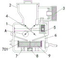
an air flow conveying device for powder materials comprises an outer shell and a feed inlet, wherein the feed inlet is embedded in the upper left corner of the outer shell, an air pump is fixedly installed at the upper right corner of the outer shell, a rotating wheel is connected to the upper middle of the outer shell in a rotating manner through a support, a sealing plate is fixedly connected to the outer side of the rotating wheel, the other end of the sealing plate is connected with a telescopic strip in a rotating manner through a hinge, limiting springs are fixedly installed on two sides of the side of the telescopic strip, a servo motor is fixedly installed at the upper right side inside the outer shell and is rotatably connected with the rotating wheel through a belt, a guide plate is fixedly installed at the middle end inside the outer shell, a filter frame is fixedly installed at the bottom end of the outer shell, a screen is fixedly installed at the outer side above the filter frame, a crushing needle is fixedly, the outer side of the upper portion of the driving motor is fixedly provided with an impeller plate, the outer side of the impeller plate is fixedly provided with bristles, and the outer side of the upper portion of the driving motor is fixedly provided with a scraper.
As a further description of the above technical solution: the outer side of the scraper blade and the bristles of the impeller plate are tightly attached to the inner wall of the screen.
As a further description of the above technical solution: the inside of scraper blade is provided with the draw-in groove, smash the needle and be in same horizontal plane with the draw-in groove in the scraper blade.
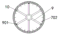
As a further description of the above technical solution: the crushing needles are arranged in a circular ring shape around the inner wall of the screen.
As a further description of the above technical solution: the distance between the two telescopic strips is larger than the opening width of the bottom of the feed inlet.
As a further description of the above technical solution: when the limiting spring is in an initial state, the telescopic strip and the sealing plate are on the same horizontal plane.
As a further description of the above technical solution: the left side fixed mounting of shell body has control switch, air pump, servo motor and driving motor all through electric connection between control switch and the external power source.
To sum up, owing to adopted above-mentioned technical scheme, the beneficial effects of the utility model are that:
1. the utility model discloses in, through installing impeller plate and scraper blade, when carrying powder material, pivoted impeller plate and scraper blade rotate, pass the screen cloth with the powder material whipping and discharge from the right side below of shell body, the powder material of reunion is when being filtered out by the screen cloth, the scraper blade can promote the powder material of reunion at screen cloth inner wall surface slip, smash with smashing after the needle contact, the brush hair of impeller plate can clean inside the screen cloth simultaneously, prevent screen cloth jam, further improvement the transport effect of device.
2. The utility model discloses in, through installing the closing plate for when the device is carrying out the in-process of reinforced transportation to powder material, servo motor can drive the closing plate and rotate, makes the pivoted closing plate carry the powder material that will drop to the device when inside, and the left and right sides of feed inlet bottom can be hugged closely to the telescopic bar on the opposite side closing plate, seals up the feed inlet bottom, prevents to produce a large amount of dusts in the transportation, further optimization operational environment.
Drawings
FIG. 1 is a schematic view of the overall structure of the present invention;
FIG. 2 is a schematic top view of a partial structure of a screen according to the present invention;
fig. 3 is an enlarged schematic structural view of fig. 1A of the present invention;
fig. 4 is a schematic sectional view of a partial structure of the middle scraper according to the present invention.
Illustration of the drawings:
1. an outer housing; 2. a feed inlet; 3. an air pump; 4. a rotating wheel; 401. a sealing plate; 402. a telescopic bar; 403. a limiting spring; 5. a servo motor; 6. a guide plate; 7. a filter frame; 701. screening a screen; 702. a pulverizing needle; 8. a drive motor; 9. an impeller plate; 901. brushing; 10. a scraper.
Detailed Description
The technical solutions in the embodiments of the present invention will be described clearly and completely with reference to the accompanying drawings in the embodiments of the present invention, and it is obvious that the described embodiments are only some embodiments of the present invention, not all embodiments. Based on the embodiments of the present invention, all other embodiments obtained by a person of ordinary skill in the art without creative efforts belong to the protection scope of the present invention.
Referring to fig. 1-4, an air flow conveying device for powder materials comprises an outer shell 1 and a feed inlet 2, the feed inlet 2 is embedded in the upper left corner of the outer shell 1, an air pump 3 is fixedly installed on the upper right corner of the outer shell 1, a rotating wheel 4 is rotatably connected above the middle of the outer shell 1 through a support, a sealing plate 401 is fixedly connected to the outer side of the rotating wheel 4, the other end of the sealing plate 401 is rotatably connected with a telescopic strip 402 through a hinge, a limiting spring 403 is fixedly installed on both sides of the telescopic strip 402, a servo motor 5 is fixedly installed on the upper right side inside the outer shell 1, the servo motor 5 is rotatably connected with the rotating wheel 4 through a belt, a guide plate 6 is fixedly installed at the middle inside end of the outer shell 1, a filter frame 7 is fixedly installed at the bottom of the outer shell 1, a screen 701 is fixedly, the bottom end of the middle part of the outer shell 1 is fixedly provided with a driving motor 8, the outer side above the driving motor 8 is fixedly provided with an impeller plate 9, the outer side of the impeller plate 9 is fixedly provided with bristles 901, and the outer side above the driving motor 8 is fixedly provided with a scraper 10.
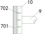
Furthermore, the outer side of the scraper 10 and the bristles 901 of the impeller plate 9 are tightly attached to the inner wall of the screen 701, so that when the agglomerated powder materials are filtered out by the screen 701, the scraper 10 pushes the agglomerated powder materials to slide on the surface of the inner wall of the screen 701, the agglomerated powder materials are in contact with the crushing needles 702 on the screen 701 and then crushed, meanwhile, the bristles 901 of the impeller plate 9 can clean the inside of the screen 701, the screen is prevented from being blocked, and the conveying effect of the device is further improved.
Furthermore, the inside of the scraper 10 is provided with a clamping groove, and the crushing needle 702 and the clamping groove in the scraper 10 are located on the same horizontal plane, so that when the scraper 10 rotates, the crushing needle 702 does not affect the normal rotation of the scraper 10.
Furthermore, the pulverizing needles 702 are arranged in a circular ring shape around the inner wall of the screen 701, so that when the agglomerated powder material is filtered out by the screen 701, the scraper 10 pushes the agglomerated powder material to slide on the inner wall surface of the screen 701, and the agglomerated powder material is pulverized by the pulverizing needles 702 after contacting with the pulverizing needles 702 on the screen 701, and the conveying effect is better.
Further, the opening width of interval ratio feed inlet 2 bottom between two telescopic strips 402 is big, carry out the in-process of reinforced transportation to powder material when the device, servo motor 5 can drive closing plate 401 and rotate, make pivoted closing plate 401 carry to the device inside with the powder material that drops, and the left and right sides of feed inlet 2 bottom can be hugged closely to telescopic strip 402 on the closing plate 401 of opposite side this moment, seal the feed inlet bottom, prevent to produce a large amount of dusts in the transportation, further operational environment has been optimized.
Further, when spacing spring 403 was in initial condition, telescopic bar 402 was in same horizontal plane with closing plate 401 for pivoted closing plate 401 is being carried to the device inside the powder material that will drop, and telescopic bar 402 on the closing plate 401 of opposite side can be through the compression of spacing spring 403 in the extrusion outside and extension, makes telescopic bar 402 hug closely the left and right sides of 2 bottoms of feed inlets just in time, seals the feed inlet bottom, prevents to produce a large amount of dusts in the transportation.
Further, the left side fixed mounting of shell body 1 has control switch, and air pump 3, servo motor 5 and driving motor 8 are all through electric connection between control switch and the external power source, are convenient for more cut off or connect the power of air pump 3, servo motor 5 and driving motor 8 through control switch, control air pump 3, servo motor 5 and driving motor 8.
The working principle is as follows: when the device is used, the device is placed on a stable ground in advance and is connected with an external power supply, when the device transports powder materials, the powder materials are poured into the feed port 2 in advance, the control switch is pressed, the servo motor 5 drives the sealing plate 401 to rotate at the moment, the rotating sealing plate 401 conveys the dropped powder materials into the device, the telescopic strips on the sealing plate on the other side are compressed by the extrusion limiting springs 403 to be tightly attached to the left side and the right side of the bottom of the feed port 2 to seal the bottom of the feed port 2 and prevent the powder materials from upwelling, the air pump 3 generates air flow to blow the powder materials into the filter frame 7, the driving motor 8 drives the impeller plate 9 and the scraper 10 to rotate, the powder materials pass through the screen 701 and are discharged from the lower right of the outer shell 1, and when the agglomerated powder materials are filtered by the screen 701, the scraper 10 pushes the agglomerated powder materials to slide on the inner wall surface of the screen 701, the agglomerated powder material is crushed after contacting with the crushing needle 702, and the brush 901 of the impeller plate 9 can clean the inside of the screen 701, so that the screen 701 is prevented from being blocked, and the conveying effect of the device is further improved.
The above, only be the concrete implementation of the preferred embodiment of the present invention, but the protection scope of the present invention is not limited thereto, and any person skilled in the art is in the technical scope of the present invention, according to the technical solution of the present invention and the utility model, the concept of which is equivalent to replace or change, should be covered within the protection scope of the present invention.
Claims (7)
1. The airflow conveying device for the powder material comprises an outer shell (1) and a feeding hole (2), wherein the feeding hole (2) is formed in the upper left corner of the outer shell (1) in an embedded mode, and is characterized in that an air pump (3) is fixedly installed at the upper right corner of the outer shell (1), a rotating wheel (4) is connected to the upper middle portion of the outer shell (1) through a support in a rotating mode, a sealing plate (401) is fixedly connected to the outer side of the rotating wheel (4), an expansion strip (402) is connected to the other end of the sealing plate (401) through a hinge in a rotating mode, limiting springs (403) are fixedly installed on two sides of the side of the expansion strip (402), a servo motor (5) is fixedly installed on the upper right portion inside the outer shell (1), the servo motor (5) is rotatably connected with the rotating wheel (4) through a belt, and a guide plate, the utility model discloses a novel filter for the kitchen range, including shell body (1), the bottom fixed mounting of shell body (1) has filter frame (7), the top outside fixed mounting of filter frame (7) has screen cloth (701), the inner wall fixed mounting of screen cloth (701) has crushing needle (702), the middle part bottom fixed mounting of shell body (1) has driving motor (8), the outside fixed mounting of driving motor (8) top has impeller plate (9), the outside fixed mounting of impeller plate (9) has brush hair (901), the outside fixed mounting of driving motor (8) top has scraper blade (10).
2. The airflow conveyor for powder materials according to claim 1, wherein the outer side of the scraper (10) and the bristles (901) of the impeller plate (9) are both in close contact with the inner wall of the screen (701).
3. The airflow conveying device for powder materials according to claim 1, wherein a clamping groove is formed in the scraper (10), and the crushing needle (702) and the clamping groove in the scraper (10) are located on the same horizontal plane.
4. The airflow transport device for powder materials according to claim 1, wherein the pulverization needles (702) are arranged in a ring shape around the inner wall of the screen (701).
5. The airflow conveyor for powder materials as claimed in claim 1, wherein the distance between the two expansion strips (402) is larger than the opening width of the bottom of the feed inlet (2).
6. The airflow transport device for powder material according to claim 1, wherein the expansion bar (402) and the sealing plate (401) are located on the same horizontal plane when the position limiting spring (403) is in the initial state.
7. The airflow conveying device for the powder material as claimed in claim 1, wherein a control switch is fixedly installed on the left side of the outer shell (1), and the air pump (3), the servo motor (5) and the driving motor (8) are electrically connected with an external power supply through the control switch.
Priority Applications (1)
| Application Number | Priority Date | Filing Date | Title |
|---|---|---|---|
| CN201921413846.2U CN210854181U (en) | 2019-08-28 | 2019-08-28 | Air flow conveying device for powder material |
Applications Claiming Priority (1)
| Application Number | Priority Date | Filing Date | Title |
|---|---|---|---|
| CN201921413846.2U CN210854181U (en) | 2019-08-28 | 2019-08-28 | Air flow conveying device for powder material |
Publications (1)
| Publication Number | Publication Date |
|---|---|
| CN210854181U true CN210854181U (en) | 2020-06-26 |
Family
ID=71284217
Family Applications (1)
| Application Number | Title | Priority Date | Filing Date |
|---|---|---|---|
| CN201921413846.2U Active CN210854181U (en) | 2019-08-28 | 2019-08-28 | Air flow conveying device for powder material |
Country Status (1)
| Country | Link |
|---|---|
| CN (1) | CN210854181U (en) |
Cited By (1)
| Publication number | Priority date | Publication date | Assignee | Title |
|---|---|---|---|---|
| CN114772225A (en) * | 2022-05-05 | 2022-07-22 | 宿州龙耀机械制造有限公司 | Scraper cleaning device |
-
2019
- 2019-08-28 CN CN201921413846.2U patent/CN210854181U/en active Active
Cited By (1)
| Publication number | Priority date | Publication date | Assignee | Title |
|---|---|---|---|---|
| CN114772225A (en) * | 2022-05-05 | 2022-07-22 | 宿州龙耀机械制造有限公司 | Scraper cleaning device |
Similar Documents
| Publication | Publication Date | Title |
|---|---|---|
| CN210854181U (en) | Air flow conveying device for powder material | |
| CN205550499U (en) | Lump coal reducing mechanism for coal mine | |
| CN218190166U (en) | Welding flux grinding machine | |
| CN210965350U (en) | Vertical mill capable of improving grinding effect | |
| CN214526920U (en) | Dry powdered coal feeder anti-clogging control device | |
| CN211801127U (en) | Broken screening rubble device in colliery | |
| CN210022449U (en) | Novel raw material mill feeding device | |
| CN209810323U (en) | Mill convenient to wash | |
| CN209335892U (en) | Rim charge separates grinding device on continuous foam cutting machine | |
| CN208482545U (en) | A kind of coal separation station-service coal briquette crushing device | |
| CN212237650U (en) | Medical medicinal material rubbing crusher | |
| CN211026588U (en) | Industrial mechanical pulverizer | |
| CN211109085U (en) | Buggy storehouse unloading mechanism | |
| CN107901217B (en) | Efficient ceramic stone processing system | |
| CN203090988U (en) | Dustproof crushing unit | |
| CN216271746U (en) | Anti-blocking device of vacuum feeding machine | |
| CN207480993U (en) | A kind of low noise dust-free pulverizing mill | |
| CN206688844U (en) | A kind of textile dyestuff reducing mechanism | |
| CN207493809U (en) | A kind of safe feed grinder for Feed Manufacturing | |
| CN214114209U (en) | Vacuum feeding machine for producing lithium battery materials | |
| CN210906346U (en) | Traditional chinese medicine processing is with omnipotent rubbing crusher | |
| CN109465986A (en) | Rim charge separates grinding device on continuous foam cutting machine | |
| CN211303336U (en) | Silicon carbide micro-powder jet mill | |
| CN216322135U (en) | Crushing processing device suitable for caking cement | |
| CN214811634U (en) | Crude stone crushing device for metal mine |
Legal Events
| Date | Code | Title | Description |
|---|---|---|---|
| GR01 | Patent grant | ||
| GR01 | Patent grant |