CN210852333U - Device for ensuring reliable connection of external plug-in of high-voltage distribution box to enable high voltage to be conducted - Google Patents
Device for ensuring reliable connection of external plug-in of high-voltage distribution box to enable high voltage to be conducted Download PDFInfo
- Publication number
- CN210852333U CN210852333U CN201921471815.2U CN201921471815U CN210852333U CN 210852333 U CN210852333 U CN 210852333U CN 201921471815 U CN201921471815 U CN 201921471815U CN 210852333 U CN210852333 U CN 210852333U
- Authority
- CN
- China
- Prior art keywords
- socket
- relay
- copper bar
- distribution box
- voltage distribution
- Prior art date
- Legal status (The legal status is an assumption and is not a legal conclusion. Google has not performed a legal analysis and makes no representation as to the accuracy of the status listed.)
- Active
Links
Images


Landscapes
- Connector Housings Or Holding Contact Members (AREA)
Abstract
The utility model discloses a device for ensuring that the high voltage can be conducted only by reliably connecting the external plug-in of a high voltage distribution box, which comprises the high voltage distribution box, wherein the bottom of the high voltage distribution box is provided with a bottom plate, one side of the bottom plate is provided with a RELAY-1RELAY, one side of the RELAY-1RELAY is provided with a RELAY-2 RELAY, and the outer wall of the high-voltage distribution box is provided with an HV-socket, an MCU + socket, an MCU-socket, an SPAR + socket, an HV-socket, an HV + socket, a DC-socket and a DC + socket, the interlocking wires of the HV-socket, the MCU + socket, the SPAR-socket, the SPAR + socket, the HV-socket, the HV + socket, the DC-socket and the DC + socket are connected with the low-voltage control wires of the RELAY-1RELAY and the RELAY-2 RELAY. Has the advantages that: the safety of the electric automobile is greatly improved.
Description
Technical Field
The utility model relates to a new energy automobile trade high voltage distribution system unit particularly, relates to one kind and ensures that the outside plug-in components of high voltage distribution box reliably connect just can lead to highly compressed device.
Background
The high-voltage Power Distribution cabinet (box/case) of the new energy electric vehicle is a high-voltage large-current Distribution Unit PDU (Power Distribution Unit) of all pure electric vehicles and plug-in hybrid electric vehicles. Adopt centralized distribution scheme, structural design is compact, and the wiring overall arrangement is convenient, overhauls convenient and fast. According to the system architecture requirements of different customers, the high-voltage distribution box is also integrated with a part of battery management system intelligent control management units, so that the complexity of the whole vehicle system architecture power distribution is further simplified. Meanwhile, the operation environment is very severe, most working conditions are under vibration and impact conditions, and the external plug-in falls off to cause disconnection or damage to the integrity of the loop of the high-voltage distribution box, so that the life safety of passengers is threatened.
An effective solution to the problems in the related art has not been proposed yet.
SUMMERY OF THE UTILITY MODEL
To the problem among the correlation technique, the utility model provides an ensure that the outside plug-in components of high voltage distribution box reliably connect just can lead to highly compressed device to overcome the above-mentioned technical problem that current correlation technique exists.
Therefore, the utility model discloses a specific technical scheme as follows:
a device for ensuring that a high voltage can be conducted only by reliably connecting an external plug-in of a high-voltage distribution box comprises the high-voltage distribution box, wherein a bottom plate is arranged at the bottom of the high-voltage distribution box, a RELAY-RELAY is arranged on one side of the bottom plate, a RELAY-RELAY is arranged on one side of the RELAY-RELAY, an LV CONNECTOR socket is arranged on one side of the outer wall of the high-voltage distribution box in an inserting mode, a first copper bar is arranged on one side of the top end of the RELAY-RELAY, a DC + socket is arranged at one end, far away from the RELAY-RELAY, of the first copper bar, the DC + socket penetrates through the inner wall of the high-voltage distribution box and extends to the outside, a second copper bar is arranged on one side, far away from the first copper bar, of the top end of the RELAY-RELAY of, one side of the second fuse is provided with a third copper bar, one end of the third copper bar, which is far away from the RELAY-RELAY, is connected with an SPAR + socket, the SPAR + socket penetrates through the high-voltage distribution box and extends to the outside, one side of the second copper bar, which is far away from the second fuse, is provided with a first fuse, one side of the first fuse is provided with a fourth copper bar, one side of the fourth copper bar, which is far away from the RELAY-RELAY, is connected with an MCU + socket, the MCU + socket penetrates through the high-voltage distribution box and extends to the outside, one side of the RELAY-RELAY, which is far away from the fifth copper bar, one end of the fifth copper bar, which is far away from the RELAY-RELAY, is provided with a DC-socket, the DC-socket penetrates through the inner wall of the high-voltage distribution box and extends to the outside, one side of the RELAY-RELAY, which is far, the MCU-socket penetrates through the inner wall of the high-voltage distribution box and extends to the outside, the other end of the SPAR-socket is connected with a copper bar seventh, one end, far away from the RELAY-RELAY, of the copper bar seventh is provided with an HV-socket, the HV-socket penetrates through the inner wall of the high-voltage distribution box and extends to the outside, the other end of the copper bar seventh is provided with an SPAR-socket, and the SPAR-socket penetrates through the inner wall of the high-voltage distribution box and extends to the outside;
the other side of the copper bar six far away from the MCU-socket is electrically connected with the negative electrodes of the + HV-socket and the + HV-socket, and the LV CONNECTOR socket is connected with the RELAY-RELAY and the RELAY-RELAY low-voltage control line and is connected with the + HV-socket, the MCU + socket, the MCU-socket, the SPAR + socket, the HV-socket, the HV + socket, the DC-socket and the DC + socket interlocking line to form a low-voltage loop.
Furthermore, in order to ensure that the high-voltage distribution box operates stably and improve the safety, the + HV-socket is connected with the first copper bar and the second copper bar through bolts.
Furthermore, in order to facilitate the cable connection between the six copper bars and the + HV 1-socket and the + HV 2-socket, so that the installation is more convenient, a screw hole is formed in one end, far away from the MCU-socket, of the six copper bars.
Furthermore, in order to improve the safety of the high-voltage distribution box, one end, far away from the RELAY-RELAY, of the copper bar III is connected with the SPAR + socket through a fuse II.
Further, in order to improve the stability of the high-voltage distribution box and further improve the safety, one side, far away from the RELAY-1RELAY, of the copper bar IV is connected with the MCU + socket through the fuse I.
Further, in order to stably fix the RELAY-1RELAY when the vehicle runs, and greatly improve the safety of the high-voltage distribution box, the RELAY-1RELAY is connected with the bottom plate through a bolt.
Further, in order to stably fix the RELAY-2 RELAY when the vehicle runs, and thus greatly improve the safety of the high-voltage distribution box, the RELAY-2 RELAY is connected with the bottom plate through a bolt.
The utility model has the advantages that:
(1) by adopting a centralized power distribution scheme, the electric automobile has the advantages of compact structural design, convenient wiring layout and convenient and quick maintenance, and is simultaneously provided with a RELAY-1RELAY and a RELAY-2 RELAY, wherein a low-voltage control line of the RELAY is connected with an LV CONNECTOR socket, + HV 1-socket, + HV 2-socket, MCU + socket, MCU-socket, SPAR + socket, HV-socket, HV + socket, DC-socket and DC + socket interlocking lines in series, so that a loop cannot be formed when the plugs are not paired, and a first fuse and a second fuse are arranged simultaneously, so that the loop cannot be formed when an external plug is damaged, and the safety of the electric automobile is greatly improved.
(2) The RELAY-1RELAY and the RELAY-2 RELAY are fixed on the bottom plate through bolts, so that the high-voltage distribution box runs stably when the electric automobile is driven, and the safety and stability of the automobile are further improved.
Drawings
In order to more clearly illustrate the embodiments of the present invention or the technical solutions in the prior art, the drawings required to be used in the embodiments will be briefly described below, and it is obvious that the drawings in the following description are only some embodiments of the present invention, and for those skilled in the art, other drawings can be obtained according to these drawings without creative efforts.
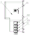
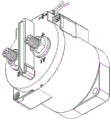
Fig. 1 is a schematic structural diagram of an apparatus for ensuring reliable connection of external plug-in components of a high voltage distribution box to allow high voltage conduction according to an embodiment of the present invention;
fig. 2 is a schematic diagram of a LV CONNECTOR receptacle of an apparatus for ensuring that an external plug of a high voltage distribution box is securely connected to allow high voltage communication, according to an embodiment of the present invention;
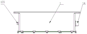
fig. 3 is a side view of an apparatus for ensuring that an external plug is securely connected to a high voltage distribution box to allow high voltage to pass, in accordance with an embodiment of the present invention;
fig. 4 is a schematic structural diagram of a sixth copper bar of a device for ensuring that an external plug-in of a high-voltage distribution box is reliably connected to enable high voltage connection according to an embodiment of the present invention;
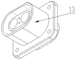
fig. 5 is a schematic structural diagram of a + HV 1-socket of a device for ensuring that an external plug of a high voltage distribution box is reliably connected to allow high voltage to pass according to an embodiment of the present invention;
fig. 6 is a schematic structural diagram of a + HV 2-socket of a device for ensuring that an external plug of a high voltage distribution box is reliably connected to allow high voltage to pass according to an embodiment of the present invention;
fig. 7 is a schematic diagram of a LV CONNECTOR receptacle of an apparatus for ensuring that external inserts of a high voltage distribution box are securely connected to enable high voltage connection, according to an embodiment of the present invention;
fig. 8 is a schematic structural diagram of an MCU + socket of an apparatus for ensuring reliable connection of an external plug-in of a high voltage distribution box to allow high voltage connection according to an embodiment of the present invention;
fig. 9 is a schematic diagram of a RELAY-1RELAY and a RELAY-2 RELAY of a device for ensuring that an external plug of a high voltage distribution box is reliably connected to enable high voltage connection according to an embodiment of the present invention;
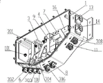
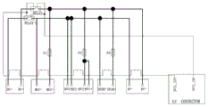
fig. 10 is a schematic diagram of an apparatus for ensuring that a plug-in external to a high voltage distribution box is securely connected to allow high voltage communication, according to an embodiment of the present invention.
In the figure:
1. a high voltage distribution box; 101. a LV CONNECTOR receptacle; 2. a base plate; 3. RELAY-1 RELAY; 301. a first copper bar; 302. a DC + socket; 303. an HV + socket; 304. a second copper bar; 305. a third copper bar; 306. a SPAR + socket; 307. a fourth copper bar; 308. MCU + socket; 4. a RELAY-2 RELAY; 5. fifthly, copper bars; 6. a DC-socket; 7. a sixth copper bar; 8. a SPAR-socket; 9. a copper bar seven; 10. an HV-socket; 11. MCU-socket; 12. a first fuse; 13. + HV 1-outlet; 14. + HV 2-outlet; 15. a second fuse; 16. and a fuse III.
Detailed Description
For further explanation of the embodiments, the drawings are provided as part of the disclosure and serve primarily to illustrate the embodiments and, together with the description, to explain the principles of operation of the embodiments, and to provide further explanation of the invention and advantages thereof, it will be understood by those skilled in the art that various other embodiments and advantages of the invention are possible, and that elements in the drawings are not to scale and that like reference numerals are generally used to designate like elements.
According to the utility model discloses an embodiment provides one kind and ensures that the outside plug-in components of high voltage distribution box reliably connect just can lead to highly compressed device.
Referring now to the drawings and the detailed description, the present invention is further illustrated, as shown in fig. 1-10, a device for ensuring reliable connection of an external plug of a high voltage distribution box to high voltage according to an embodiment of the present invention, including a high voltage distribution box 1, a bottom plate 2 is disposed at the bottom of the high voltage distribution box 1, a RELAY-1RELAY 3 is disposed at one side of the bottom plate 2, a RELAY-2 RELAY 4 is disposed at one side of the RELAY-1RELAY 3, an LV CONNECTOR socket 101 is inserted into one side of the outer wall of the high voltage distribution box 1, a first copper bar 301 is disposed at one side of the top end of the RELAY-1RELAY 3, a DC + socket 302 is disposed at one end of the first copper bar 301 away from the RELAY-1RELAY 3, the DC + socket 302 penetrates through the inner wall of the high voltage distribution box 1 and extends to the outside, and a second copper bar 304 is disposed at one side of the top end of the RELAY-1RELAY 3 away from the first, an HV + socket 303 and a first fuse 12 and a second fuse 15 are arranged at one end of the second copper bar 304, which is far away from the RELAY-1RELAY 3, a copper bar three 305 is arranged at one side of the second fuse 15, one end of the copper bar three 305, which is far away from the RELAY-1RELAY 3, is connected with the SPAR + socket 306, the SPAR + socket 306 penetrates through the high-voltage distribution box 1 and extends to the outside, a first fuse 12 is arranged at one side of the second copper bar 304, which is far away from the second fuse 15, a copper bar four 307 is arranged at one side of the first fuse 12, one side of the copper bar four 307, which is far away from the RELAY-1RELAY 3, is connected with an MCU + socket 308, the MCU + socket 308 penetrates through the high-voltage distribution box 1 and extends to the outside, a copper bar five 5 is arranged at one side of the RELAY-2 RELAY 4, a DC-socket 6 is arranged at, the DC-socket 6 penetrates through the inner wall of the high-voltage distribution box 1 and extends to the outside, one side, away from the copper bar five 5, of the RELAY-2 RELAY 4 is provided with a copper bar six 7, one end, away from the RELAY-2 RELAY 4, of the copper bar six 7 is connected with an MCU-socket 11, the MCU-socket 11 penetrates through the inner wall of the high-voltage distribution box 1 and extends to the outside, the other end of the SPAR-socket 8 is connected with a copper bar seven 9, one end, away from the RELAY-2 RELAY 4, of the copper bar seven 9 is provided with an HV-socket 10, the HV-socket 10 penetrates through the inner wall of the high-voltage distribution box 1 and extends to the outside, the other end of the HV-socket is provided with an SPAR-socket 8, and the SPAR-socket 8 penetrates through the inner wall of the;
wherein, the three fuses 16 are connected with the positive cables of the + HV 1-socket 13 and the + HV 2-socket 14, the other side is connected with the copper bar two 304 cable, and the side of the copper bar six 7 far away from the MCU-socket 11 is electrically connected with the negative electrodes of the + HV 1-socket 13 and the + HV 2-socket 14, the LV CONNECTOR socket 101 is connected with the RELAY-1RELAY 3 and the RELAY-2 RELAY 4 low voltage control line and is connected with the + HV 1-socket 13, the + HV 2-socket 14, the MCU + socket 308, the MCU-socket 11, the SPAR-socket 8, the SPAR + socket 306, the HV-socket 10, the HV + socket 303, the DC-socket 6 and the DC + socket 302 interlocking line to form a low voltage loop.
By means of the technical scheme, a centralized power distribution scheme is adopted, the structure design is compact, the wiring layout is convenient, the overhaul is convenient and fast, the RELAY-1RELAY 3 and the RELAY-2 RELAY 4 are arranged, low-voltage control lines of the RELAY-1RELAY and the RELAY-2 RELAY are connected with the LVCONNECTOR socket 101, + HV 1-socket 13, + HV 2-socket 14, MCU + socket 308, MCU-socket 11, SPAR-socket 8, SPAR + socket 306, HV-socket 10, HV + socket 303, DC-socket 6 and DC + socket 302 interlocking lines in series, so that a loop cannot be formed when the plugs are not paired, and the fuse I12, the fuse II 15 and the fuse III 16 are arranged simultaneously, so that a loop cannot be formed when an external plug is damaged, and the safety of the electric automobile is greatly improved; the RELAY-1RELAY 3 and the RELAY-2 RELAY 4 are fixed on the bottom plate 2 through bolts, so that the high-voltage distribution box 1 runs stably when the electric automobile is driven, and the safety stability of the automobile is further improved.
In one embodiment, the + HV 1-socket 13 is connected with the first copper bar 301 and the second copper bar 304 through bolts, so that the operation stability of the high voltage distribution box 1 is improved, and the safety is improved.
In one embodiment, the end of the copper bar seven 9 far away from the MCU-socket 11 is provided with a screw hole, thereby facilitating the cable connection of the copper bar seven 9 with the + HV 1-socket 13 and the + HV 2-socket 14, and further facilitating the installation.
In one embodiment, one end of the copper bar III 305 far away from the RELAY-1RELAY 3 is connected with the SPAR + socket 306 through a fuse II 15, so that the safety of the high-voltage distribution box 1 is improved.
In one embodiment, one side of the copper bar four 307, which is far away from the RELAY-1RELAY 3, is connected with the MCU + socket 308 through the fuse one 12, so that the stability of the high voltage distribution box 1 is improved, and the safety is further improved, so that the RELAY-1RELAY 3 is stably fixed when the vehicle runs again, and the safety of the high voltage distribution box 1 is greatly improved.
In one embodiment, the RELAY-1RELAY 3 is connected with the bottom plate 2 through bolts, so that the RELAY-1RELAY 3 is stably fixed when a vehicle runs, and the safety of a high-voltage distribution box is greatly improved.
In one embodiment, the RELAY-2 RELAY 4 is connected to the base plate 2 by bolts, so that the RELAY-2 RELAY 4 is stably fixed when the vehicle is driven, thereby greatly improving the safety of the high voltage distribution box 1.
In one embodiment, the high voltage box RELAY-1RELAY is connected in a loop with the RELAY-2 RELAY and all the card interlock lines. One of the connectors is loosened or falls off, the interlocking loop is disconnected, the relay stops working, and high voltage is cut off, so that the safety is greatly improved.
The working principle is as follows: 1. LV CONNECTOR socket 101 and + HV 1-socket 13, + HV 2-socket 14, MCU + socket 308, MCU-socket 11, SPAR-socket 8, SPAR + socket 306, HV-socket 10, HV + socket 303, DC-socket 6 and DC + socket 302 of high-voltage distribution box 1 are plugged with the plug of the whole vehicle wiring harness end, the low-voltage power supply of the whole vehicle, generally 11V 24V low-voltage power supply, of the whole vehicle on the market at present, is controlled by the whole vehicle communication LV CONNECTOR socket 101, and RELAY-1RELAY-2 also needs to be selected to meet the corresponding power supply requirement. The HVILIN of the LV CONNECTOR socket 101 corresponds to the low-voltage positive level of the whole vehicle, and the HVIL-OUT corresponds to the low-voltage negative pole of the whole vehicle.
The wiring harness inside the high-voltage distribution box 1 is connected as follows:
and (3) positive electrode: LV CONNECTOR socket 101HVIL _ IN → RELAY-1Relay 3 and RELAY-2 Relay 4 low voltage control line + (two low voltage control lines are connected IN parallel);
negative electrode: LV CONNECTOR socket 101HVIL _ OUT → DC + socket 302 interlock pin bit a, DC + socket 302 interlock pin bit b → DC-socket 6 interlock pin bit b;
DC-socket 6 interlock pin bit a → HV + socket 303 interlock pin bit b, HV + socket 303 interlock pin bit a → HV-socket 10 interlock pin bit b;
HV-socket 10 interlock pin bit a → SPAR + socket 306 interlock pin bit b, SPAR + socket 306 interlock pin bit a → SPAR-socket 8 interlock pin bit b;
SPAR-socket 8 interlocking pin bit a → MCU-socket 11 interlocking pin bit b, MCU-socket 11 interlocking pin bit a → MCU + socket 308 interlocking pin bit b;
MCU + socket 308 interlock pin bit a → + HV 2-socket 14 interlock pin bit b, + HV 2-socket 14 interlock pin bit a → + HV 1-socket 13 interlock pin bit b;
+ HV 1-socket 13 interlock pin bit a → RELAY-1RELAY 3 and MCU + socket 308 low voltage control line- (two low voltage control lines in parallel);
2. when connected as above, the interlocking pin bits a and b of the + HV 1-socket 13, + HV 2-socket 14, + MCU + socket 308, MCU-socket 11, SPAR-socket 8, SPAR + socket 306, HV-socket 10, HV + socket 303, DC-socket 6, DC + socket 302 plug are all non-conductive, and when the plug is mated with the high voltage distribution box 1 socket, the following loop is formed (as long as no plug is mated, the loop cannot be formed):
and (3) positive electrode: LV CONNECTOR socket 101HVIL _ IN → RELAY-1Relay 3 and RELAY-2 Relay 4 low voltage control line + (two low voltage control lines are connected IN parallel);
negative electrode: LV CONNECTOR jack 101HVIL _ OUT → DC + jack 302 interlock pin bit a → DC + jack 302 interlock pin bit b → DC-jack 6 interlock pin bit b →;
DC-socket 6 interlock pin bit a → HV + socket 303 interlock pin bit b → HV + socket 303 interlock pin bit a → HV-socket 10 interlock pin bit b →;
HV-socket 10 interlock pin bit a → SPAR + socket 306 interlock pin bit b → SPAR + socket 306 interlock pin bit a → SPAR-socket 8 interlock pin bit b →;
SPAR-socket 8 interlocking pin bit a → MCU-socket 11 interlocking pin bit b → MCU-socket 11 interlocking pin bit a → MCU + socket 308 interlocking pin bit b →;
MCU + jack 308 interlock pin bit a → + HV 2-jack 14 interlock pin bit b → + HV 2-jack 14 interlock pin bit a → + HV 1-jack 13 interlock pin bit b →;
+ HV 1-socket 13 interlock pin bit a → RELAY-1RELAY 3 and RELAY-2 RELAY 4 low voltage control line- (two low voltage control lines in parallel);
when the whole vehicle supplies power to the LV CONNECTOR socket 101 (HVIL _ IN corresponds to positive electricity of the whole vehicle, HVIL _ IN corresponds to negative electricity of the whole vehicle), the whole interlocking circuit is conducted, and after the low-voltage control lines of the RELAY-1RELAY 3 and the RELAY-2 RELAY 4 are electrified, a high-voltage electric shock is conducted, so that complete control is realized. (wherein, the RELAY-1RELAY 3 and the RELAY-2 RELAY 4 are RELAYs, the main functions are that the low-voltage control line is supplied with power, the two high-voltage contacts are conducted, the low-voltage power supply is cut off, and the two high-voltage contacts are cut off). when any pair of plug and socket is abnormally and reliably connected, the whole interlocking loop is cut off, and the RELAY-1RELAY 3 and the RELAY-2 RELAY 4 can not supply power, so the high-voltage power supply is automatically cut off.
In conclusion, by adopting a centralized power distribution scheme, the electric vehicle has the advantages of compact structural design, convenient wiring layout and convenient and quick maintenance, and is simultaneously provided with a RELAY-1RELAY 3 and a RELAY-2 RELAY 4, wherein low-voltage control lines of the RELAYs are connected in series with an LV CONNECTOR socket 101, a + HV 1-socket 13, a + HV 2-socket 14, an MCU + socket 308, an MCU-socket 11, an SPAR-socket 8, an SPAR + socket 306, an HV-socket 10, an HV + socket 303, a DC-socket 6 and a DC + socket 302 through interlocking lines, so that a loop cannot be formed when the plugs are not paired, and a fuse I12, a fuse II 15 and a fuse III 16 are arranged simultaneously, so that the loop cannot be formed when an external plug is damaged, and the safety of the electric vehicle is greatly improved; the RELAY-1RELAY 3 and the RELAY-2 RELAY 4 are fixed on the bottom plate 2 through bolts, so that the high-voltage distribution box 1 runs stably when the electric automobile is driven, and the safety stability of the automobile is further improved.
In the present invention, unless otherwise expressly stated or limited, the terms "mounted," "disposed," "connected," "fixed," "screwed" and the like are to be construed broadly, e.g., as meaning fixedly connected, detachably connected, or integrally formed; can be mechanically or electrically connected; they may be directly connected or indirectly connected through an intermediate medium, and may be connected through the inside of two elements or in an interaction relationship between two elements, unless otherwise specifically defined, and the specific meaning of the above terms in the present invention will be understood by those skilled in the art according to specific situations.
The above description is only a preferred embodiment of the present invention, and should not be taken as limiting the invention, and any modifications, equivalent replacements, improvements, etc. made within the spirit and principle of the present invention should be included in the protection scope of the present invention.
Claims (7)
1. The device for ensuring that the external plug of the high-voltage distribution box is reliably connected to be communicated with high voltage comprises a high-voltage distribution box (1), and is characterized in that a bottom plate (2) is arranged at the bottom of the high-voltage distribution box (1), a RELAY-1RELAY (3) is arranged on one side of the bottom plate (2), a RELAY-2 RELAY (4) is arranged on one side of the RELAY-1RELAY (3), an LV CONNECTOR socket (101) is inserted into one side of the outer wall of the high-voltage distribution box (1), a first copper bar (301) is arranged on one side of the top end of the RELAY-1RELAY (3), a DC + socket (302) is arranged at one end, away from the RELAY-1RELAY (3), the DC + socket (302) penetrates through the inner wall of the high-voltage distribution box (1) and extends to the outside, and a second copper bar (304) is arranged on one side, away from the first copper bar (301), at the top end of the RELAY, one end, far away from the RELAY-1RELAY (3), of the second copper bar (304) is provided with an HV + socket (303) and is provided with a first fuse (12) and a second fuse (15), one side of the second fuse (15) is provided with a third copper bar (305), one end, far away from the RELAY-1RELAY (3), of the third copper bar (305) is connected with a SPAR + socket (306), the SPAR + socket (306) penetrates through the high-voltage distribution box (1) and extends to the outside, one side, far away from the second fuse (15), of the second copper bar (304) is provided with the first fuse (12), one side of the first fuse (12) is provided with a fourth copper bar (307), one side, far away from the RELAY-1RELAY (3), of the fourth copper bar (307) is connected with the MCU + socket (308), and the MCU + socket (308) penetrates through the high-voltage distribution box (1) and extends to the, one side of the RELAY-2 RELAY (4) is provided with a fifth copper bar (5), one end, far away from the RELAY-2 RELAY (4), of the fifth copper bar (5) is provided with a DC-socket (6), the DC-socket (6) penetrates through the inner wall of the high-voltage distribution box (1) and extends to the outside, one side, far away from the fifth copper bar (5), of the RELAY-2 RELAY (4) is provided with a sixth copper bar (7), one end, far away from the RELAY-2 RELAY (4), of the sixth copper bar (7) is connected with an MCU-socket (11), the MCU-socket (11) penetrates through the inner wall of the high-voltage distribution box (1) and extends to the outside, the other end of the SPAR-socket (8) is connected with a seventh copper bar (9), one end, far away from the RELAY-2 RELAY (4), of the seventh copper bar (9) is provided with an HV-socket (, the HV-socket (10) penetrates through the inner wall of the high-voltage distribution box (1) and extends to the outside, and the other end of the HV-socket is provided with a SPAR-socket (8), and the SPAR-socket (8) penetrates through the inner wall of the high-voltage distribution box (1) and extends to the outside;
wherein the third fuse (16) is connected with the positive cables of the + HV 1-socket (13) and the + HV 2-socket (14), the other side is connected with the cable of the second copper bar (304), and one side of the copper bar six (7) far away from the MCU-socket (11) is electrically connected with the negative poles of the + HV 1-socket (13) and the + HV 2-socket (14), the LV CONNECTOR socket (101) is connected with the RELAY-1RELAY (3) and the RELAY-2 RELAY (4) low voltage control lines and is connected with the + HV 1-socket (13), the + HV 2-socket (14), the MCU + socket (308), the MCU-socket (11), the SPAR-socket (8), the SPAR + socket (306), the HV-socket (10), the HV + socket (303), the DC-socket (6) and the DC + socket (302) interlocking lines to form a low voltage loop.
2. The device for ensuring the reliable connection of the external plug of a high voltage distribution box to high voltage according to claim 1, characterized in that the + HV 1-socket (13) is bolted to the first copper bar (301) and the second copper bar (304).
3. Device for ensuring the reliable connection of external plug-ins of high voltage distribution boxes to high voltage conduction according to claim 1, characterized in that the end of said copper bar six (7) remote from said MCU-socket (11) is provided with a threaded hole.
4. Device for ensuring the reliable connection of external plug-ins of high-voltage distribution boxes to high-voltage conduction according to claim 1, characterized in that the end of the copper bar three (305) remote from the RELAY-1RELAY (3) is connected to the SPAR + socket (306) through a fuse two (15).
5. A device for ensuring the reliable connection of external plug-ins of high voltage distribution boxes to high voltage conduction according to claim 1, characterized in that the side of the copper bar four (307) remote from said RELAY-1RELAY (3) is connected to said MCU + socket (308) through a fuse one (12).
6. A device for ensuring a reliable connection of external inserts of a high voltage distribution box to high voltage connections according to claim 1, characterized in that the RELAY-1RELAY (3) is bolted to the base plate (2).
7. A device for ensuring a reliable connection of external inserts of a high voltage distribution box to high voltage connections according to claim 1, characterized in that the RELAY-2 RELAY (4) is bolted to the base plate (2).
Priority Applications (1)
| Application Number | Priority Date | Filing Date | Title |
|---|---|---|---|
| CN201921471815.2U CN210852333U (en) | 2019-09-05 | 2019-09-05 | Device for ensuring reliable connection of external plug-in of high-voltage distribution box to enable high voltage to be conducted |
Applications Claiming Priority (1)
| Application Number | Priority Date | Filing Date | Title |
|---|---|---|---|
| CN201921471815.2U CN210852333U (en) | 2019-09-05 | 2019-09-05 | Device for ensuring reliable connection of external plug-in of high-voltage distribution box to enable high voltage to be conducted |
Publications (1)
| Publication Number | Publication Date |
|---|---|
| CN210852333U true CN210852333U (en) | 2020-06-26 |
Family
ID=71290192
Family Applications (1)
| Application Number | Title | Priority Date | Filing Date |
|---|---|---|---|
| CN201921471815.2U Active CN210852333U (en) | 2019-09-05 | 2019-09-05 | Device for ensuring reliable connection of external plug-in of high-voltage distribution box to enable high voltage to be conducted |
Country Status (1)
| Country | Link |
|---|---|
| CN (1) | CN210852333U (en) |
-
2019
- 2019-09-05 CN CN201921471815.2U patent/CN210852333U/en active Active
Similar Documents
| Publication | Publication Date | Title |
|---|---|---|
| CN103481792A (en) | High-voltage distribution box for power battery | |
| CN103826925B (en) | For the electric power connecting box of motor vehicle driven by mixed power | |
| CN109703376B (en) | System for realizing electric interlocking of workshop power supply cabinet | |
| CN102856797A (en) | Easy-to-maintain compact high-voltage distribution box | |
| CN210852333U (en) | Device for ensuring reliable connection of external plug-in of high-voltage distribution box to enable high voltage to be conducted | |
| CN202319944U (en) | Electric power management device for electric vehicle | |
| CN210283910U (en) | Device for switching high-voltage circuit based on low-voltage dual control | |
| CN218300111U (en) | Battery system and electric working machine | |
| CN114744433A (en) | Remove quick switching device of energy storage emergency power source | |
| CN214874640U (en) | High-voltage distributing box for automobile | |
| CN204347089U (en) | For the combined connection box of electric energy acquisition terminal | |
| CN210296817U (en) | Battery package coupling assembling, battery package module and battery package | |
| KR101758416B1 (en) | Power relay assembly for electric vehiccle | |
| CN220914786U (en) | Quick connector switching device and box transformer matched with quick connector of low-voltage cable | |
| CN221090507U (en) | High-voltage box of electric automobile | |
| CN221080746U (en) | High-voltage distribution box for new energy engineering vehicle | |
| CN219246767U (en) | High-voltage interlocking device, battery system and vehicle | |
| CN219833052U (en) | High-voltage box for power battery pack | |
| CN219611021U (en) | Power distribution cabinet with quick low-voltage emergency access device of power generation vehicle | |
| CN217281414U (en) | Mobile energy storage emergency power supply quick access device | |
| CN213150822U (en) | Integrated structure of fuel cell stack and manual maintenance switch | |
| CN111619349A (en) | Power distribution device and vehicle using same | |
| CN221043572U (en) | Charging gun control box and charging gun | |
| CN211428115U (en) | Accumulator fuse box for electric vehicle | |
| CN218300508U (en) | Wiring harness switching device and battery replacement station |
Legal Events
| Date | Code | Title | Description |
|---|---|---|---|
| GR01 | Patent grant | ||
| GR01 | Patent grant |