CN210850364U - External auditory canal shaver - Google Patents
External auditory canal shaver Download PDFInfo
- Publication number
- CN210850364U CN210850364U CN201921530492.XU CN201921530492U CN210850364U CN 210850364 U CN210850364 U CN 210850364U CN 201921530492 U CN201921530492 U CN 201921530492U CN 210850364 U CN210850364 U CN 210850364U
- Authority
- CN
- China
- Prior art keywords
- rotating shaft
- shaver
- machine body
- blades
- auditory canal
- Prior art date
- Legal status (The legal status is an assumption and is not a legal conclusion. Google has not performed a legal analysis and makes no representation as to the accuracy of the status listed.)
- Expired - Fee Related
Links
Images


Abstract
The utility model discloses an external auditory canal shaver belongs to the medical instrument field. Four arc-shaped blades are fixed between the two cutter frame discs and positioned on the outer side surfaces of the cutter frame discs in a surrounding mode, the right middle parts of the blades protrude outwards, an oval metal mesh enclosure attached to the outside of the blades is sleeved outside the cutter head, when the rotating shaft rotates, the four blades are driven to rotate at a high speed along the inner side walls of the metal mesh enclosure, and the most outwards protruding parts in the middles of the arc-shaped side surfaces of the cutter head can be well attached to the inner walls of the auditory canals; the hair can stretch into the hair-catching device from the meshes on the metal net cover, so that the hair can be cut by the rotating blade, the fan blades fixed on the rotating shaft rotate together with the rotating shaft, so that the air flow is driven to flow to the negative pressure chamber from the position of the cutter head and finally flows into the impurity storage chamber, the air flow flows out from the side surface of the body and the air-permeable grids corresponding to the impurity storage chamber, and the hair with larger particles is blocked and remained in the impurity storage chamber, so that the discharge and the collection of the cut and dropped hair can be completed; the blade is positioned in the metal mesh enclosure to ensure the safety of shaving.
Description
Technical Field
The utility model belongs to the field of medical equipment, concretely relates to external auditory canal shaver.
Background
When the external auditory canal operation is carried out, the external auditory canal hair of part of patients is longer, thereby influencing the operation visual field and increasing the operation risk. In order to remove the external auditory canal hair, the small scissors are mostly used for cutting off the external auditory canal hair in the prior art, and the inner wall of the auditory canal of a human body is bent, so that the external auditory canal hair is not convenient to cut off, and the sharp scissors are easy to scratch the epidermal tissue.
To this patent no: CN201821326328.2 discloses an electric shaver for external auditory meatus, in which the cutting edge of the blade and the protection pad are located on the same plane, the cutting edge of the blade is at a certain angle with the inner wall of the external auditory meatus, and the protection pad can be slightly compressed when the blade rotates for shaving, so that the blade can better contact with the inner wall of the external auditory meatus, but there are some disadvantages: the hair of scraping off on the one hand can't in time be discharged the duct, and its blade of on the other hand exposes outside and be straight form, can't laminate on crooked duct inner wall and thoroughly clear up hair, if there is bellied skin pimple on the duct inner wall will have the possibility of cutting fish tail.
SUMMERY OF THE UTILITY MODEL
The utility model discloses the technical problem who solves: aiming at the problem that the prior electric external auditory canal shaver cannot deal with the inner wall of the bent auditory canal for trimming and the exposed blade easily causes scratch, the external auditory canal shaver which is safe, has good trimming effect and can automatically discharge and cut hair is provided.
In order to solve the technical problem, the utility model discloses a as follows technical scheme be:
a shaver for external auditory meatus comprises a machine body and a shaver head; the utility model discloses a portable multifunctional cutting machine, including organism, cutter head, baffle A, baffle B, power room, connecting pipe, connecting channel, cutter head fixed connection, baffle A, baffle B, power room, the one end dead center position fixedly connected with connecting pipe of organism, the inside of connecting pipe is equipped with connecting channel to connecting channel communicates with each other with the inner cavity of organism, cutter head fixed connection is on the other end of connecting pipe, the inside of organism is fixedly connected with in proper order and is close to the baffle A of connecting pipe, and is located the baffle B of baffle A opposite side to two baffles separate the inner cavity of organism into triplex, the miscellaneous room of storage that is located between baffle A and the baffle B in the organism, be located the negative pressure chamber between baffle A and the connecting pipe in the organism, and be located the power room of position between baffle B and the organism bottom, dead center position.
Wherein, the tool bit comprises a tool rest disk A and a tool rest disk B which are fixedly connected on the rotating shaft in sequence, the tool rest disk A is fixedly connected with the tail end of the rotating shaft towards the positive center of one side of the tool rest disk B, four blades distributed in a cross shape are arranged between the two tool rest disks and around the tool rest disks, each blade is arc-shaped, the positive middle section of each blade protrudes outwards, the cutting edge of each blade is positioned at two sides of each blade, two ends of each blade are respectively and fixedly connected on the tool rest disks A and the tool rest disks B, the outermost side of the tool bit is sleeved with a metal mesh enclosure, the side surface of the metal mesh enclosure is oval, the blades positioned inside are close to the inner side wall of the metal mesh enclosure, the side surface of the metal mesh enclosure is provided with meshes, one end of the metal mesh enclosure, which faces the connecting pipe, is provided with a cylindrical fixed end, and the internal thread sleeve is sleeved on the tail end of the connecting pipe, and the tail end of the connecting pipe is provided with an external thread matched with the internal thread sleeve for screwing and fixing.
The blade support device comprises four blades and is characterized in that cross support bodies sleeved on a rotating shaft are arranged in the middle sections of the four blades, the cross support bodies are made of rubber materials, and the outermost sides of the cross support bodies are abutted to the inner surfaces of the corresponding blades.
The center of the cutter frame disk B is provided with a center hole C for the rotating shaft to pass through, and the cutter frame disk B is provided with fan-shaped through holes C distributed around the center hole C.
The center of one end of the connecting pipe close to the cutter head is provided with a central hole A for the rotating shaft to pass through, and the tail end of the connecting pipe is provided with fan-shaped through holes A distributed around the central hole A.
The center of the partition plate A is provided with a center hole B for the rotating shaft to pass through, fan-shaped through holes B are uniformly distributed around the center hole B and are formed in the partition plate A, the partition plate A faces one side of the partition plate B, and a bearing concentric with the center hole B is embedded in the center of the partition plate A.
Wherein, the negative pressure chamber is internally provided with fan blades fixed on the rotating shaft.
The power chamber is internally provided with a driven gear fixed on a rotating shaft at the bottom of the machine body, a motor is fixedly connected in the power chamber, and a driving gear meshed with the driven gear is fixedly connected to an output shaft of the motor.
Wherein, the side of the machine body and the position corresponding to the impurity storage chamber are provided with air permeable grids which are communicated with the inside and the outside.
Compared with other methods, the utility model, beneficial technological effect is:
the cutter head is sleeved with an elliptical metal mesh enclosure attached to the four blades, when the rotating shaft rotates, the four blades are driven to rotate at a high speed along the inner side wall of the metal mesh enclosure, the part of the cutter head extends into and is attached to the inner wall of an auditory canal, and the most outward convex part in the middle of the arc-shaped side surface of the cutter head can be well attached to the inner wall of the auditory canal; the hair can stretch into the cutter head from the mesh holes on the metal mesh enclosure, so as to be cut by the rotating blade, the fan blades fixed on the rotating shaft in the negative pressure chamber in the machine body rotate along with the rotating shaft, further the air flow is driven to flow to the negative pressure chamber from the position of the cutter head, and finally flows into the impurity storage chamber, the air flow flows out from the side surface of the machine body and the air-permeable grids corresponding to the impurity storage chamber, and the hair with larger particles is blocked and left in the impurity storage chamber, so that the discharge and the collection of the cut and dropped hair are finished; the blade is positioned in the metal mesh enclosure to ensure the safety of shaving.
Drawings
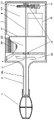
FIG. 1 is a schematic view of the overall structure of the device of the present invention;
fig. 2 is an enlarged schematic view of the tool bit 3 in the device of the present invention shown in fig. 1;
fig. 3 is a structural view of the metal mesh 7 in fig. 1 or 2;
FIG. 4 is a cross-sectional view taken along the line A-A in FIG. 2;
FIG. 5 is a side view of partition A4 of FIG. 1;
FIG. 6 is a side view of the cutter head disk B6 of FIG. 2;
FIG. 7 is a left side view of the end of the connector tube 2 of FIG. 2;
1. a body; 101. a negative pressure chamber; 102. a trash storage chamber; 103. a power chamber; 104. a gas permeable grid; 2. a connecting pipe; 201. a connecting channel; 202. a fan-shaped through hole A; 203. a central hole A; 3. a cutter head; 4. a separator A; 401. a fan-shaped through hole B; 402. a central hole B; 5. a tool head disk A; 6. a tool holder disk B; 601. a fan-shaped through hole C; 602. a central hole C; 7. a metal mesh enclosure; 701. mesh openings; 702. a fixed end; 8. a rotating shaft; 9. a cross support; 10. a blade; 11. an internally threaded sleeve; 12. a partition board B; 13. a driven gear; 14. a bearing; 15. a motor; 16. a drive gear; 17. a fan blade.
Detailed Description
The technical solutions in the embodiments of the present invention will be described clearly and completely with reference to the accompanying drawings in the present application, and it is obvious that the described embodiments are only some embodiments of the present invention, not all embodiments. Based on the embodiments of the present invention, all other embodiments obtained by a person skilled in the art without creative efforts belong to the protection scope of the present invention. The words "upper", "lower", "left" and "right" when used herein are merely intended to designate corresponding upper, lower, left and right directions in the drawings, and do not limit the structure thereof.
An external auditory canal shaver shown in fig. 1 comprises a body 1 and a cutter head 3; the right center of one end of the machine body 1 is fixedly connected with a connecting pipe 2, a connecting channel 201 is arranged inside the connecting pipe 2, the connecting channel 201 is communicated with the inner cavity of the machine body 1, and the connecting channel 201 is used for allowing the hair cut by the cutter head 3 to flow into the machine body 1 and be collected uniformly; the cutter head 3 is fixedly connected to the other end of the connecting pipe 2, a partition plate A4 close to the connecting pipe 2 and a partition plate B12 positioned on the other side of the partition plate A4 are fixedly connected inside the machine body 1 in sequence, the inner cavity of the machine body 1 is divided into three parts by the two partition plates, an impurity storage chamber 102 is arranged in the machine body 1 and between the partition plate A4 and the partition plate B12, and the impurity storage chamber 102 is used for collecting and storing cut hairs; a negative pressure chamber 101 located in the machine body 1 and between the partition board a4 and the connecting pipe 2, the negative pressure chamber 101 is used for generating flowing air flow so as to drive the cut and dropped hair to move; and a power chamber 103 located between the partition B12 and the bottom of the machine body 1, wherein the power chamber 103 is used for placing and installing power components; the positive central point position rotates in organism 1 and is connected with pivot 8, the one end of pivot 8 is pegged graft in the bearing 14 that is located 1 inner chamber bottom of organism to run through organism 1 and connecting pipe 2 and finally extend to in the tool bit 3, pivot 8 is used for driving the rotatory cutting of blade 10, and drives the rotation of flabellum 17 and then produce the air current that flows, in order to be used for the debris hair discharge duct that produces the cutting of tool bit 3 part.
As shown in fig. 2, the cutter head 3 includes a cutter frame disk a5 and a cutter frame disk B6 fixedly connected to the rotating shaft 8 in sequence, the cutter frame disk a6 is fixedly connected to the end of the rotating shaft 8 at a position facing to the right center of one side of the cutter frame disk B6, as shown in fig. 1 and 3, four blades 10 distributed in a cross shape are arranged between the two cutter frame disks and around the cutter frame disks, each blade 10 is arc-shaped, and the right middle section of each blade protrudes outwards, and the structure is such that the part, protruding outwards from the right middle of each blade 10, can better fit with the inner wall of a curved auditory canal and improves the shaving effect compared with a straight blade; the cutting edges of the blades 10 are positioned on two sides of the blades, and two ends of the blades 10 are respectively fixedly connected to a cutter frame disk A5 and a cutter frame disk B6, and the cutter frame disks are used for bearing and mounting the blades 10; the outermost side of the cutter head 3 is sleeved with a metal mesh enclosure 7, as shown in fig. 2 and 3, the side surface of the metal mesh enclosure 7 is elliptical, the blade 10 positioned inside is close to the inner side wall of the metal mesh enclosure, and the side surface of the metal mesh enclosure 7 is provided with meshes 701, so that the blade 10 can move along with the inner side wall of the metal mesh enclosure 7 when rotating at a high speed along with the rotating shaft 8, and when the hair in the auditory canal extends into the cutter head 3 from the meshes 701 on the metal mesh enclosure 7, the hair can be cut by the rotating blade 10 and fall into the cutter head 3; on the metal mesh enclosure 7 and towards the one end of connecting pipe 2 be equipped with cylindric stiff end 702, as shown in fig. 2, stiff end 702 has cup jointed internal thread sleeve 11 outward, and internal thread sleeve 11 cup joints on the terminal position of connecting pipe 2, the end of connecting pipe 2 is equipped with and is used for connecing soon fixedly with internal thread sleeve 11 matched with external screw thread, can overlap metal mesh enclosure 7 in the blade 10 outside like this to fix on the end of connecting pipe 2 through connecing soon, when needs clean tool bit 3, can screw down metal mesh enclosure 7, because blade 10 has certain toughness, compressible blade 10 removes to the center and makes metal mesh enclosure 7 break away from at last when pulling out metal mesh enclosure 7, conveniently maintains cleanness to metal mesh enclosure 7 and blade 10.
As shown in fig. 1 and 3, a cross support 9 sleeved on the rotating shaft 8 is disposed at an inner middle position of four blades 10, the cross support 9 is made of rubber, and an outermost side of the cross support 9 abuts against an inner surface of the corresponding blade 10, the cross support 9 is used for shaping the blade 10 to keep an arc state, and on the other hand, the rubber is convenient for the blade 10 to compress and deform towards the middle when the metal mesh enclosure 7 is detached.
As shown in fig. 6, a center hole C602 for the rotating shaft 8 to pass through is formed in the center of the cutter holder disk B6, and the cutter holder disk B6 is provided with fan-shaped through holes C601 distributed around the center hole C602, and the fan-shaped through holes C601 are used for air flow, so that cut and fallen hairs are driven to flow to the connecting channel 201 together, and finally flow to the impurity storage chamber 102 to be collected uniformly.
As shown in fig. 7, a central hole a203 for the rotation shaft 8 to pass through is opened at the center of one end of the connecting tube 2 near the cutter head 3, and fan-shaped through holes a202 distributed around the central hole a203 are provided at the end of the connecting tube 2, and the same fan-shaped through holes a202 are used for the air flow to pass through to drive the cut hairs to flow to the connecting channel 201.
As shown in fig. 5, the center of the partition a4 is provided with a central hole B402 for the rotating shaft 8 to pass through, and the partition a4 is provided with fan-shaped through holes B401 uniformly distributed around the central hole B402, the fan-shaped through holes B401 are used for air flow to drive the hair to pass through and finally flow into the impurity storage chamber 102; the partition plate A4 faces the side of the partition plate B12, and a bearing 14 concentric with the central hole B402 is embedded in the right center of the partition plate A4, and the bearing 14 is used for receiving the rotating shaft 8 and keeping the rotating shaft stable in rotation.
As shown in fig. 1, a fan 17 fixed on the rotating shaft 8 is disposed in the negative pressure chamber 101 for rotating and driving the air flow to flow, so as to absorb the fallen hair.
A driven gear 13 fixed on the rotating shaft 8 is arranged at the bottom of the machine body 1 and in the power chamber 103, a motor 15 is fixedly connected in the power chamber 103, and a driving gear 16 meshed with the driven gear 13 is fixedly connected to an output shaft of the motor 15, so that the rotating shaft 8 is driven to rotate by the motor 15.
As shown in fig. 1, an air permeable grid 104 is disposed on the side of the body 1 and corresponding to the impurity storage chamber 102 for communicating the inside and the outside, and is used for exhausting air from the impurity storage chamber 102 to form a flowing air flow channel.
The present invention has been further described with reference to specific embodiments, but it should be understood that the specific description herein should not be construed as limiting the spirit and scope of the present invention, and that various modifications to the above-described embodiments, which would occur to persons skilled in the art after reading this specification, are within the scope of the present invention.
Claims (9)
1. An external auditory canal shaver comprises a machine body (1) and a shaver head (3), and is characterized in that a connecting pipe (2) is fixedly connected to the center of one end of the machine body (1), a connecting channel (201) is arranged inside the connecting pipe (2), the connecting channel (201) is communicated with an inner cavity of the machine body (1), the shaver head (3) is fixedly connected to the other end of the connecting pipe (2), a partition board A (4) close to the connecting pipe (2) and a partition board B (12) positioned on the other side of the partition board A (4) are sequentially and fixedly connected to the inside of the machine body (1), the inner cavity of the machine body (1) is divided into three parts by the two partition boards, a sundry storage chamber (102) positioned between the partition board A (4) and the partition board B (12) in the machine body (1), and a negative pressure chamber (101) positioned between the partition board A (4) and the connecting pipe (2) in the machine body (1), and the power chamber (103) is positioned between the partition plate B (12) and the bottom of the machine body (1), the right center position in the machine body (1) is rotatably connected with a rotating shaft (8), one end of the rotating shaft (8) is inserted into a bearing (14) positioned at the bottom of the inner cavity of the machine body (1) and penetrates through the machine body (1) and the connecting pipe (2) to finally extend into the cutter head (3).
2. The external auditory canal shaver according to claim 1, wherein the shaver head (3) comprises a holder disk A (5) and a holder disk B (6) fixedly connected to the rotating shaft (8) in turn, the holder disk A (5) is fixedly connected to the end of the rotating shaft (8) at a position facing to the center of one side of the holder disk B (6), four blades (10) are arranged between the holder disks and around the holder disk in a cross-shaped manner, each blade (10) is arc-shaped and protrudes outwards from the middle section thereof, the cutting edges of the blades (10) are located at both sides thereof, and both ends of the blades (10) are fixedly connected to the holder disk A (5) and the holder disk B (6), respectively, the outermost side of the shaver head (3) is provided with a metal mesh (7) which is sleeved with an oval side surface, and the blades (10) located inside are made to be close to the inner side wall thereof, and open mesh (701) to metal mesh enclosure (7) side, metal mesh enclosure (7) are gone up and are equipped with cylindric stiff end (702) towards the one end of connecting pipe (2), stiff end (702) cup joints internal thread sleeve (11) outward, and internal thread sleeve (11) cup joint on the terminal position of connecting pipe (2), the end of connecting pipe (2) is equipped with and is used for connecing fixedly soon with internal thread sleeve (11) matched with external screw thread.
3. The external auditory canal shaver according to claim 2, wherein the four blades (10) are provided with cross supports (9) at the inner middle positions thereof, which are sleeved on the rotating shaft (8), the cross supports (9) are made of rubber, and the outermost sides of the cross supports (9) abut against the inner surfaces of the corresponding blades (10).
4. An external auditory canal shaver as in claim 2, wherein the holder disk B (6) is centrally provided with a central hole C (602) through which the rotary shaft (8) passes, and wherein the holder disk B (6) is provided with fan-shaped through holes C (601) distributed around the central hole C (602).
5. The external auditory canal shaver according to claim 1, wherein the connecting tube (2) has a central hole (A203) through which the rotating shaft (8) passes at a position at the center of one end near the position of the cutter head (3), and the connecting tube (2) has fan-shaped through holes (A202) distributed around the central hole (A203) at the end.
6. An external auditory canal shaver according to claim 1, wherein the center of the partition A (4) is provided with a center hole B (402) for passing the rotating shaft (8), and the partition A (4) is provided with fan-shaped through holes B (401) evenly distributed around the center hole B (402), and a bearing (14) concentric with the center hole B (402) is embedded in the center of the partition A (4) and faces one side of the partition B (12).
7. An external auditory canal shaver as claimed in claim 1, characterized in that the negative pressure chamber (101) is provided with vanes (17) fixed to the rotary shaft (8).
8. An external auditory canal shaver as claimed in claim 1, wherein the power chamber (103) is provided with a driven gear (13) fixed on the rotating shaft (8) at the bottom of the machine body (1), a motor (15) is fixedly connected in the power chamber (103), and a driving gear (16) meshed with the driven gear (13) is fixedly connected on the output shaft of the motor (15).
9. An external auditory canal shaver as claimed in claim 1, wherein the side of the body (1) and the position corresponding to the storage chamber (102) are provided with air-permeable grids (104) communicating the inside and the outside.
Priority Applications (1)
| Application Number | Priority Date | Filing Date | Title |
|---|---|---|---|
| CN201921530492.XU CN210850364U (en) | 2019-09-16 | 2019-09-16 | External auditory canal shaver |
Applications Claiming Priority (1)
| Application Number | Priority Date | Filing Date | Title |
|---|---|---|---|
| CN201921530492.XU CN210850364U (en) | 2019-09-16 | 2019-09-16 | External auditory canal shaver |
Publications (1)
| Publication Number | Publication Date |
|---|---|
| CN210850364U true CN210850364U (en) | 2020-06-26 |
Family
ID=71306053
Family Applications (1)
| Application Number | Title | Priority Date | Filing Date |
|---|---|---|---|
| CN201921530492.XU Expired - Fee Related CN210850364U (en) | 2019-09-16 | 2019-09-16 | External auditory canal shaver |
Country Status (1)
| Country | Link |
|---|---|
| CN (1) | CN210850364U (en) |
Cited By (1)
| Publication number | Priority date | Publication date | Assignee | Title |
|---|---|---|---|---|
| CN113413220A (en) * | 2021-06-03 | 2021-09-21 | 宜昌市中心人民医院(三峡大学第一临床医学院、三峡大学附属中心人民医院) | Neurosurgery skin preparation device |
-
2019
- 2019-09-16 CN CN201921530492.XU patent/CN210850364U/en not_active Expired - Fee Related
Cited By (1)
| Publication number | Priority date | Publication date | Assignee | Title |
|---|---|---|---|---|
| CN113413220A (en) * | 2021-06-03 | 2021-09-21 | 宜昌市中心人民医院(三峡大学第一临床医学院、三峡大学附属中心人民医院) | Neurosurgery skin preparation device |
Similar Documents
| Publication | Publication Date | Title |
|---|---|---|
| CN102551957B (en) | Portable multifunctional electric ear digging device | |
| CN210130877U (en) | Sampling device for oral mucosa | |
| CN210850364U (en) | External auditory canal shaver | |
| CN112294398B (en) | Clean storage device of supersound sword integral type for surgery operation | |
| CN204318840U (en) | A kind of bone-cutting device of department of otorhinolaryngology | |
| CN106942338B (en) | A kind of hand electric fish scale scraper | |
| CN208714052U (en) | External auditory canal shaver | |
| CN212421374U (en) | Shaver capable of automatically cleaning | |
| CN113143177A (en) | Medical otology operation inspection instrument with earhair clearance function | |
| CN207220022U (en) | A kind of hand electric fish scale scraper | |
| CN208681661U (en) | A kind of razor head and the shaver comprising the razor head | |
| CN206699275U (en) | A kind of environment-friendly type donkey meat processing deburring equipment | |
| CN105821615A (en) | Hair ball trimming and collecting integrated equipment | |
| CN206804324U (en) | A kind of medical anorectal surgical peels off device for excising | |
| CN220297167U (en) | Scraper with detachable cutter head | |
| CN213328289U (en) | Cloth thread end removing device for garment processing | |
| CN202682151U (en) | Portable type multifunctional motor-driven earpick device | |
| CN219255643U (en) | Preoperative ear nose position hair trimmer | |
| CN116725768B (en) | Preoperative ear hair removing device for skin preparation | |
| CN203539533U (en) | Comfortable ear picker | |
| CN215131545U (en) | Practical tool for drawing ears | |
| CN213826056U (en) | Dust collecting equipment for ophthalmologic instrument | |
| CN211656882U (en) | Weeding device is used in gardens | |
| CN218593044U (en) | Vibrissa cleaner | |
| CN217139698U (en) | Waste gas treatment device of flame cutting machine |
Legal Events
| Date | Code | Title | Description |
|---|---|---|---|
| GR01 | Patent grant | ||
| GR01 | Patent grant | ||
| CF01 | Termination of patent right due to non-payment of annual fee |
Granted publication date: 20200626 Termination date: 20210916 |
|
| CF01 | Termination of patent right due to non-payment of annual fee |